center console MERCEDES-BENZ SPRINTER 2010 MY10 Operator’s Manual
[x] Cancel search | Manufacturer: MERCEDES-BENZ, Model Year: 2010, Model line: SPRINTER, Model: MERCEDES-BENZ SPRINTER 2010Pages: 292, PDF Size: 6.75 MB
Page 132 of 292
!
The right and left storage spaces may be
loaded with a maximum of 11 lbs (5 kg)
each.
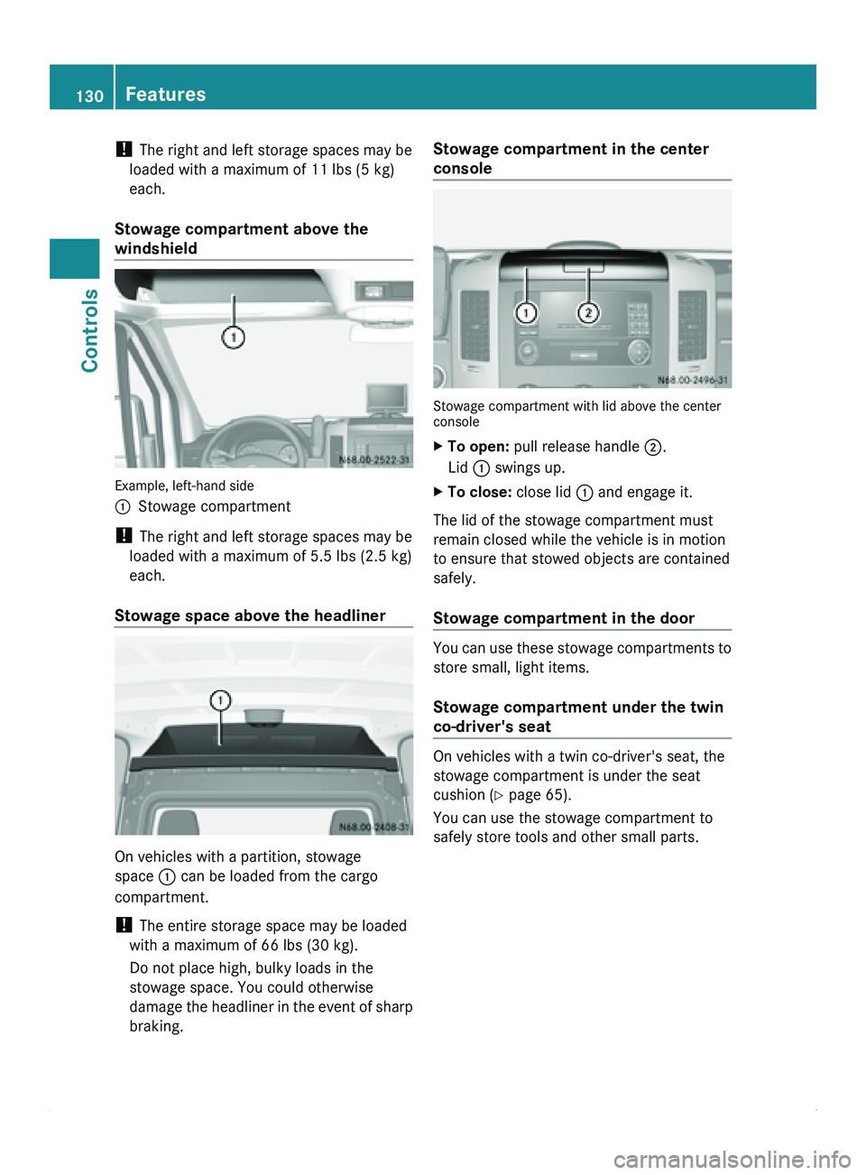
Stowage compartment above the
windshield Example, left-hand side
0046
Stowage compartment
! The right and left storage spaces may be
loaded with a maximum of 5.5 lbs (2.5 kg)
each.
Stowage space above the headliner On vehicles with a partition, stowage
space 0046 can be loaded from the cargo
compartment.
!
The entire storage space may be loaded
with a maximum of 66 lbs (30 kg).
Do not place high, bulky loads in the
stowage space. You could otherwise
damage the headliner
in the event of sharp
braking. Stowage compartment in the center
console
Stowage compartment with lid above the center
console
X
To open: pull release handle 0047.
Lid 0046 swings up.
X To close: close lid 0046 and engage it.
The lid of the stowage compartment must
remain closed while the vehicle is in motion
to ensure that stowed objects are contained
safely.
Stowage compartment in the door You can use these stowage compartments to
store small, light items.
Stowage compartment under the twin
co-driver's seat
On vehicles with a twin co-driver's seat, the
stowage compartment is under the seat
cushion (
Y page 65).
You can use the stowage compartment to
safely store tools and other small parts. 130
Features
Controls
Page 134 of 292
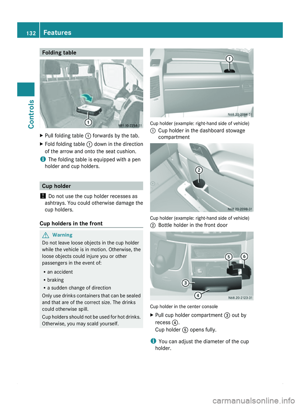
Folding table
X
Pull folding table 0046 forwards by the tab.
X Fold folding table 0046 down in the direction
of the arrow and onto the seat cushion.
i The folding table is equipped with a pen
holder and cup holders. Cup holder
! Do not use the cup holder recesses as
ashtrays. You could
otherwise damage the
cup holders.
Cup holders in the front G
Warning
Do not leave loose objects in the cup holder
while the vehicle is in motion. Otherwise, the
loose objects could injure you or other
passengers in the event of:
R an accident
R braking
R a sudden change of direction
Only use drinks
containers that can be sealed
and that are of the correct size. The drinks
could otherwise spill.
Cup holders should not be used for hot drinks.
Otherwise, you may scald yourself. Cup holder (example: right-hand side of vehicle)
0046
Cup holder in the dashboard stowage
compartment Cup holder (example: right-hand side of vehicle)
0047
Bottle holder in the front door Cup holder in the center console
X
Pull cup holder compartment 008A out by
recess
0088.
Cup holder 0086 opens fully.
i You can adjust the diameter of the cup
holder. 132
Features
Controls
Page 135 of 292
X
Place the beverage container in cup
holder 0086.
X Push clamping arm 0087 against the
container.
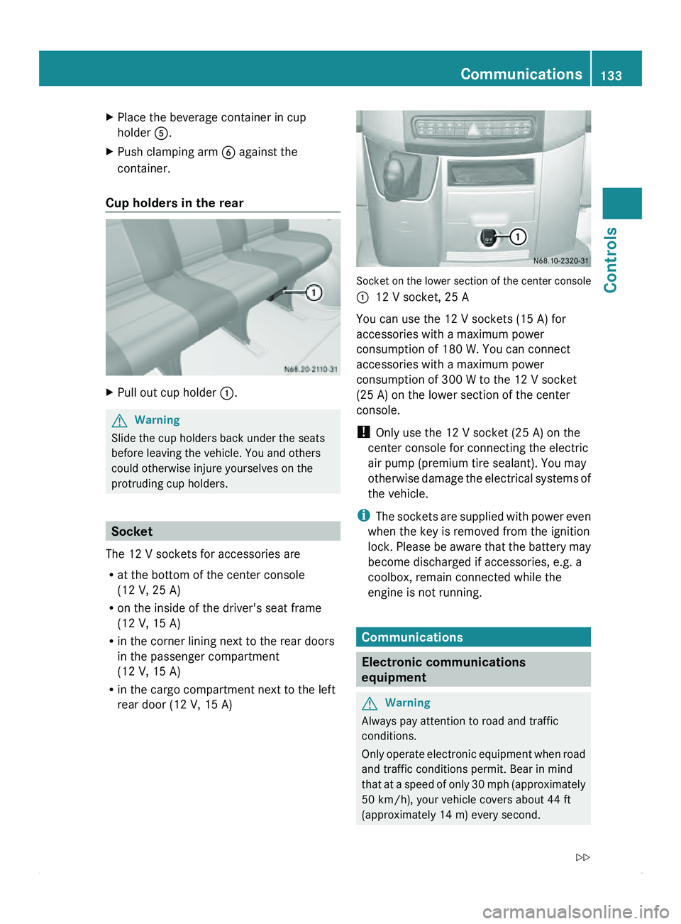
Cup holders in the rear X
Pull out cup holder 0046.G
Warning
Slide the cup holders back under the seats
before leaving the vehicle. You and others
could otherwise injure yourselves on the
protruding cup holders. Socket
The 12 V sockets for accessories are
R at the bottom of the center console
(12 V, 25 A)
R on the inside of the driver's seat frame
(12 V, 15 A)
R in the corner lining next to the rear doors
in the passenger compartment
(12 V, 15 A)
R in the cargo compartment next to the left
rear door (12 V, 15 A) Socket on the lower section of the center console
0046
12 V socket, 25 A
You can use the 12 V sockets (15 A) for
accessories with a maximum power
consumption of 180 W. You can connect
accessories with a maximum power
consumption of 300 W to the 12 V socket
(25 A) on the lower section of the center
console.
! Only use the 12 V socket (25 A) on the
center console for connecting the electric
air pump (premium tire sealant). You may
otherwise
damage the electrical systems of
the vehicle.
i The sockets are supplied with power even
when the key is removed from the ignition
lock. Please be aware that the battery may
become discharged if accessories, e.g. a
coolbox, remain connected while the
engine is not running. Communications
Electronic communications
equipment
G
Warning
Always pay attention to road and traffic
conditions.
Only operate electronic
equipment when road
and traffic conditions permit. Bear in mind
that at a speed of only 30 mph (approximately
50 km/h), your vehicle covers about 44 ft
(approximately 14 m) every second. Communications
133
Controls
Z
Page 226 of 292
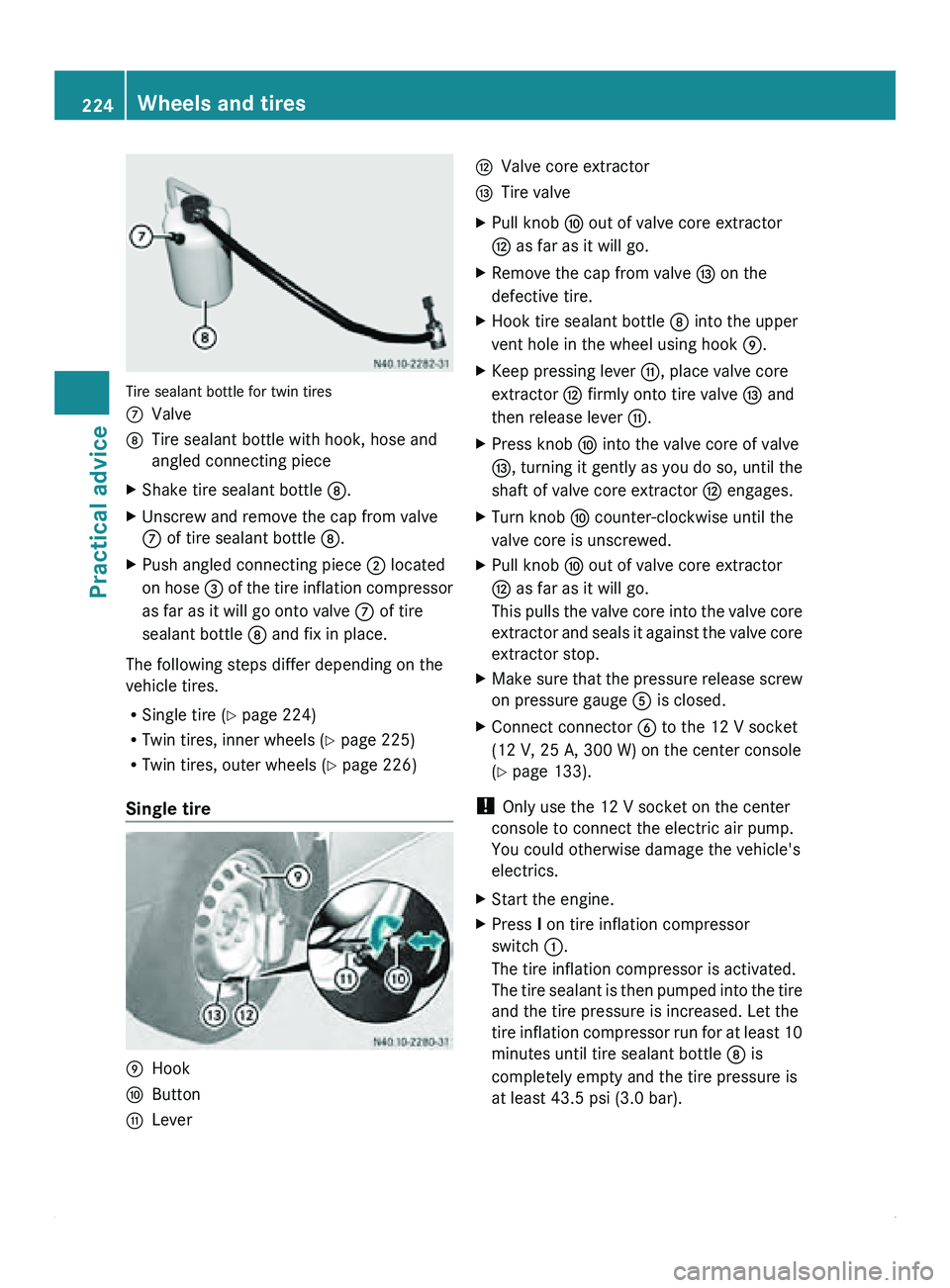
Tire sealant bottle for twin tires
006E
Valve
006F Tire sealant bottle with hook, hose and
angled connecting piece
X Shake tire sealant bottle 006F.
X Unscrew and remove the cap from valve
006E of tire sealant bottle 006F.
X Push angled connecting piece 0047 located
on hose 008A
of the tire inflation compressor
as far as it will go onto valve 006E of tire
sealant bottle 006F and fix in place.
The following steps differ depending on the
vehicle tires.
R Single tire (Y page 224)
R Twin tires, inner wheels ( Y page 225)
R Twin tires, outer wheels (
Y page 226)
Single tire 0070
Hook
0071 Button
0072 Lever 0073
Valve core extractor
0074 Tire valve
X Pull knob 0071 out of valve core extractor
0073 as far as it will go.
X Remove the cap from valve 0074 on the
defective tire.
X Hook tire sealant bottle 006F into the upper
vent hole in the wheel using hook 0070.
X Keep pressing lever 0072, place valve core
extractor 0073 firmly onto tire valve 0074 and
then release lever 0072.
X Press knob 0071 into the valve core of valve
0074, turning it gently as you do so, until the
shaft of valve core extractor 0073 engages.
X Turn knob 0071 counter-clockwise until the
valve core is unscrewed.
X Pull knob 0071 out of valve core extractor
0073 as far as it will go.
This pulls
the
valve core into the valve core
extractor and seals it against the valve core
extractor stop.
X Make sure that the pressure release screw
on pressure gauge 0086 is closed.
X Connect connector 0087 to the 12 V socket
(12 V, 25 A, 300 W) on the center console
(Y page 133).
! Only use the 12 V socket on the center
console to connect the electric air pump.
You could otherwise damage the vehicle's
electrics.
X Start the engine.
X Press I on tire inflation compressor
switch 0046.
The tire inflation compressor is activated.
The tire sealant
is then pumped into the tire
and the tire pressure is increased. Let the
tire inflation compressor run for at least 10
minutes until tire sealant bottle 006F is
completely empty and the tire pressure is
at least 43.5 psi (3.0 bar). 224
Wheels and tires
Practical advice
Page 228 of 292
X
Hook tire sealant bottle 006F into the upper
vent hole in the wheel using hook 0072.
X Push angled connecting piece 0074 located
on the hose of tire sealant filler bottle 006F
as far
as
it will go on to valve core extractor
0071 and fix it in place.
X Make sure that the pressure release screw
on pressure gauge 0086 is closed.
X Connect connector 0087 to the 12 V socket
(12 V, 25 A, 300 W) on the center console
(Y page 133).
! Only use the 12 V socket on the center
console to connect the electric air pump.
You could otherwise damage the vehicle's
electrics.
X Start the engine.
X Press I on tire inflation compressor
switch 0046.
The tire inflation compressor is activated.
The tire
sealant
is then pumped into the tire
and the tire pressure is increased. Let the
tire inflation compressor run for at least 10
minutes until tire sealant bottle 006F is
completely empty and the tire pressure is
at least 43.5 psi (3.0 bar).
! Do not
run
the electric air pump for longer
than 20 minutes without a break; otherwise
it may overheat.
The air pump can be used again once it has
cooled down.
X Inflate the tire using the tire inflation
compressor until the recommended tire
pressure ( Y page 281) is reached.
X Then, press 0 on tire inflation compressor
switch 0046.
The tire inflation compressor is
deactivated.
X Slide knob 0073 quickly to the stop in valve
core extractor 0071.
X Turn knob 0073 clockwise
until
the valve core
is firmly screwed into tire valve 0075.i
Do not pull the valve core extractor from
the tire valve while the valve core is
unscrewed from the
tire valve. Tire sealant
could otherwise escape and make you
dirty.
The tire sealant is water-soluble. If tire
sealant escapes, you can wash it away with
water.
X Pull knob 0073 out of valve core extractor
0071 as far as it will go.
X Unscrew valve core extractor 0071 counter-
clockwise from tire valve 0075.
X Screw valve extension 0070 onto tire valve
0075 and tighten it.
X Screw the valve cap onto valve extension
0070.
After filling with tire sealant, ( Y page 228).
Twin tires, outer wheel The tire valve is located on the inside of the
outer wheel and should be positioned
horizontally on the left side of the wheel for
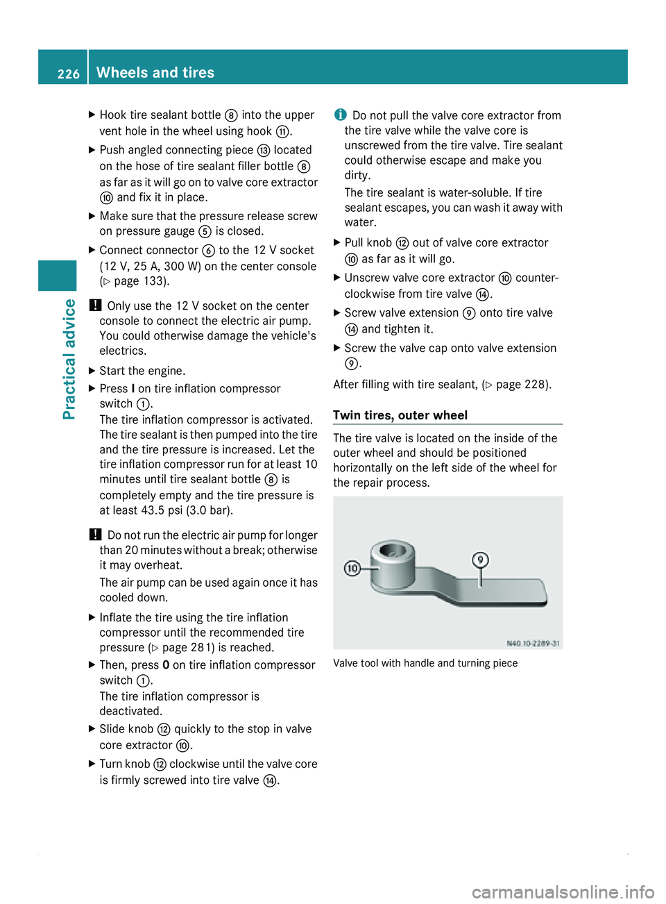
the repair process.
Valve tool with handle and turning piece226
Wheels and tires
Practical advice
Page 229 of 292
0070
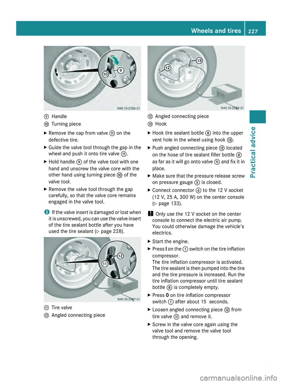
Handle
0071 Turning piece
X Remove the cap from valve 0072 on the
defective tire.
X Guide the valve tool through the gap in the
wheel and push it onto tire valve 0072.
X Hold handle 0070 of the valve tool with one
hand and unscrew the valve core with the
other hand using turning piece 0071 of the
valve tool.
X Remove the valve tool through the gap
carefully, so that the valve core remains
engaged in the valve tool.
i If the
valve
insert is damaged or lost when
it is unscrewed, you can use the valve insert
of the tire sealant bottle after you have
used the tire sealant ( Y page 228).0072
Tire valve
0073 Angled connecting piece 0073
Angled connecting piece
0074 Hook
X Hook tire sealant bottle 006F into the upper
vent hole in the wheel using hook 0074.
X Push angled connecting piece 0073 located
on the hose of tire sealant filler bottle 006F
as far
as
it will go onto valve 0072 and fix it in
place.
X Make sure that the pressure release screw
on pressure gauge 0086 is closed.
X Connect connector 0087 to the 12 V socket
(12 V, 25 A, 300 W) on the center console
(Y page 133).
! Only use the 12 V socket on the center
console to connect the electric air pump.
You could otherwise damage the vehicle's
electrics.
X Start the engine.
X Press I on the 0046
switch on the tire inflation
compressor.
The tire inflation compressor is activated.
The tire sealant is then pumped into the tire
and the tire pressure is increased. Run the
tire inflation compressor until tire sealant
bottle 006F is completely empty.
X Press 0 on tire inflation compressor
switch 0046 after about 15 seconds.
X Loosen angled connecting piece 0073 from
tire valve 0072 and remove it.
X Screw in the valve core again using the
valve tool and remove the valve tool
through the opening. Wheels and tires
227
Practical advice Z
Page 243 of 292
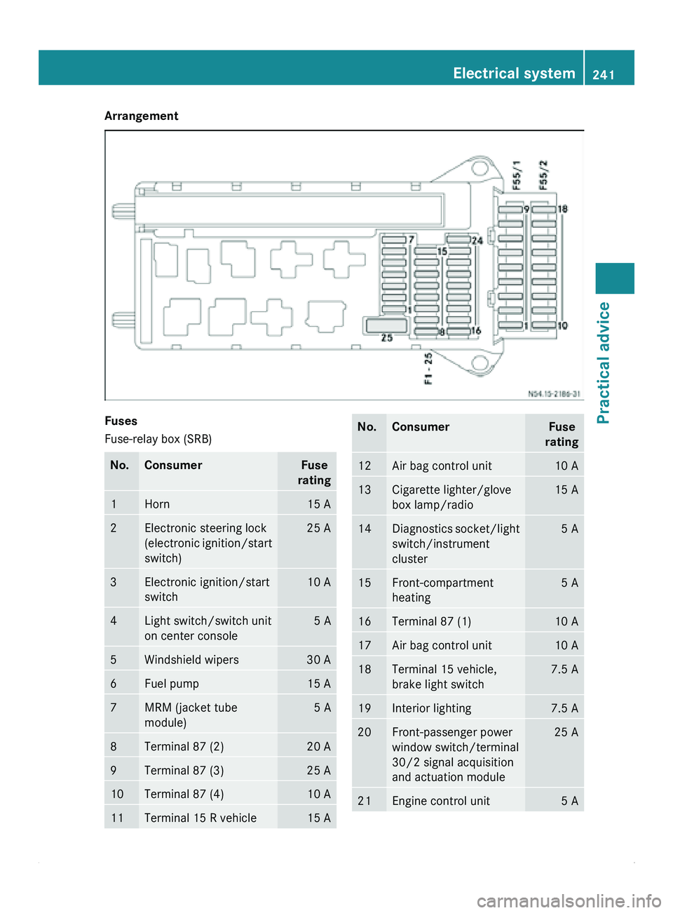
Arrangement
Fuses
Fuse-relay box (SRB)
No. Consumer Fuse
rating 1 Horn 15 A
2 Electronic steering lock
(electronic ignition/start
switch) 25 A
3 Electronic ignition/start
switch 10 A
4 Light switch/switch unit
on center console 5 A
5 Windshield wipers 30 A
6 Fuel pump 15 A
7 MRM (jacket tube
module) 5 A
8 Terminal 87 (2) 20 A
9 Terminal 87 (3) 25 A
10 Terminal 87 (4) 10 A
11 Terminal 15 R vehicle 15 A No. Consumer Fuse
rating 12 Air bag control unit 10 A
13 Cigarette lighter/glove
box lamp/radio 15 A
14 Diagnostics socket/light
switch/instrument
cluster 5 A
15 Front-compartment
heating 5 A
16 Terminal 87 (1) 10 A
17 Air bag control unit 10 A
18 Terminal 15 vehicle,
brake light switch 7.5 A
19 Interior lighting 7.5 A
20 Front-passenger power
window switch/terminal
30/2 signal acquisition
and actuation module 25 A
21 Engine control unit 5 AElectrical system
241Practical advice Z
Page 244 of 292
No. Consumer Fuse
rating 22 Brake system (ABS) 5 A
23 Starter motor 20 A
24 Engine components 10 A
25 12 V socket in the center
console 25 A
Fuse block F55/1
No. Consumer Fuse
rating 1 Left door control unit 25 A
2 Diagnostics socket 10 A
3 Brake system (valves) 25 A
4 Brake system (delivery
pump) 40 A
5 Terminal 87 (5) engine 7.5/10 A
6 Terminal 87 (6) engine 7.5/10 A
7 Headlamp cleaning
system 30 A
8 Anti-theft alarm system
(ATA) 15 A
9 Additional turn signal
module 10 A
Fuse block F55/2
No. Consumer Fuse
rating 10 Radio 15 A
11 Mobile phone 7.5 A
12 Blower, front/auxiliary
heating blower setting 1 30 A
13 Auxiliary heating digital
timer, radio receiver/
basic wiring DIN-
slot 7.5 A No. Consumer Fuse
rating 14 Seat heating 30 A
15 Unassigned —
16 Heating, rear-
compartment heating/
front-compartment air
conditioning/CD player 10 A
17 Motion detector/
convenience lighting 10 A
18 Rear-compartment air-
conditioning system 7.5 A
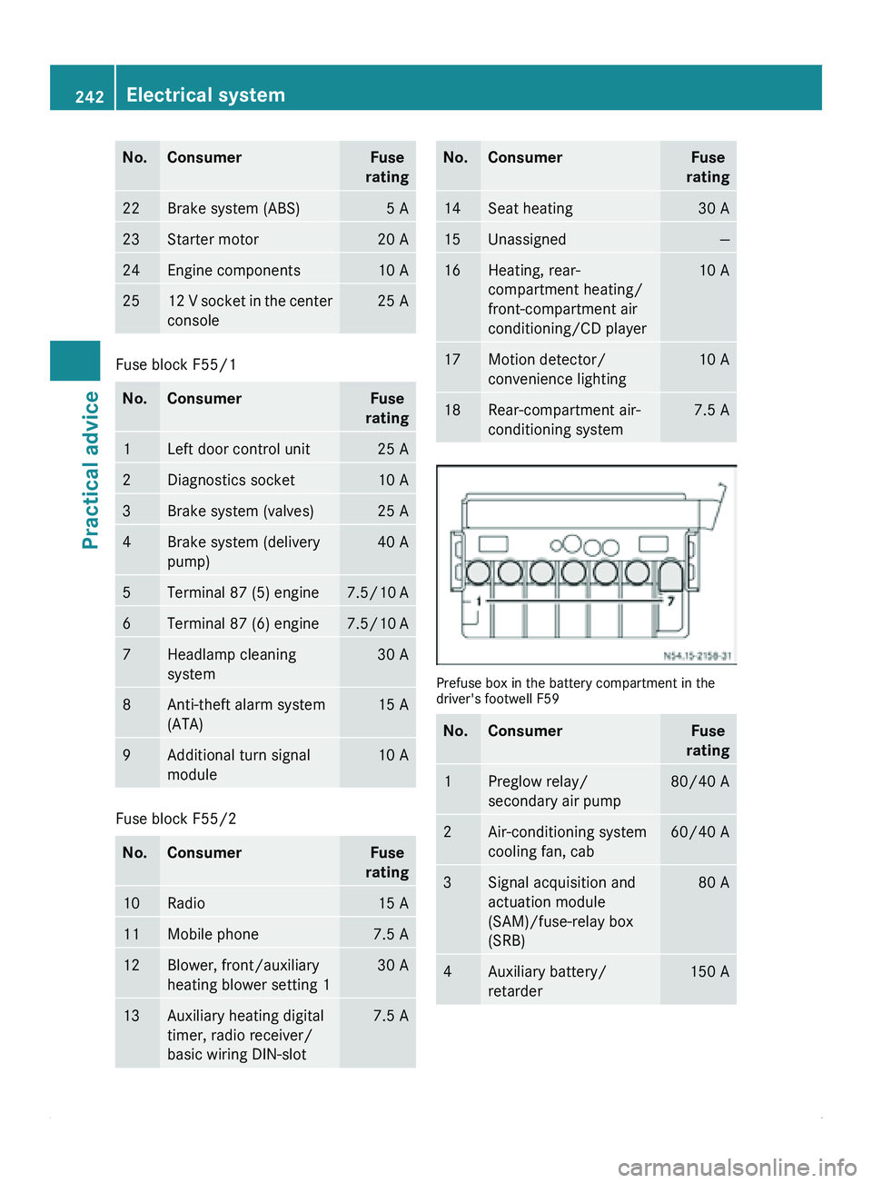
Prefuse box in the battery compartment in the
driver's footwell F59
No. Consumer Fuse
rating 1 Preglow relay/
secondary air pump 80/40 A
2 Air-conditioning system
cooling fan, cab 60/40 A
3 Signal acquisition and
actuation module
(SAM)/fuse-relay box
(SRB) 80 A
4 Auxiliary battery/
retarder 150 A242
Electrical systemPractical advice