clock MERCEDES-BENZ SPRINTER 2010 MY10 Operator’s Manual
[x] Cancel search | Manufacturer: MERCEDES-BENZ, Model Year: 2010, Model line: SPRINTER, Model: MERCEDES-BENZ SPRINTER 2010Pages: 292, PDF Size: 6.75 MB
Page 144 of 292
reduced in volume each time reverse gear
is engaged.
Refueling
G
Warning
Fuel is highly flammable. Fire, naked flames
and smoking as well as the use of auxiliary
heaters (sparks) are therefore prohibited
when handling fuel.
Switch off the
engine and the auxiliary heating
before refueling. G
Warning
Avoid any contact with fuels.
You can damage your health if your skin
comes into direct contact with fuel or if you
inhale fuel vapors.
0040Environmental note
If fuels are handled improperly, they pose a
danger to persons and the environment. Do
not allow fuels
to run into the sewage system,
the surface waters, the ground water or into
the ground.
! Filter the fuel
before transferring it to the
vehicle if you are refueling the vehicle from
barrels or containers.
This will prevent malfunctions in the fuel
system due to contaminated fuel. G
Warning
Do not use gasoline to refuel vehicles with a
diesel engine. Never
mix diesel with gasoline.
This causes damage to the fuel system and
engine and could result in the vehicle catching
fire.
! Do not use gasoline to refuel vehicles with
a diesel engine. Even small amounts of
gasoline will cause damage to the fuel
system and engine. Damage resulting from
adding gasoline is not covered by the New
Vehicle Limited Warranty. !
If the wrong fuel has been added by
mistake, do not switch on the ignition. If
you do, the fuel could enter the fuel lines.
The tank and the fuel lines must then be
drained. Inform a qualified specialist
workshop and have the tank and the fuel
lines drained completely.
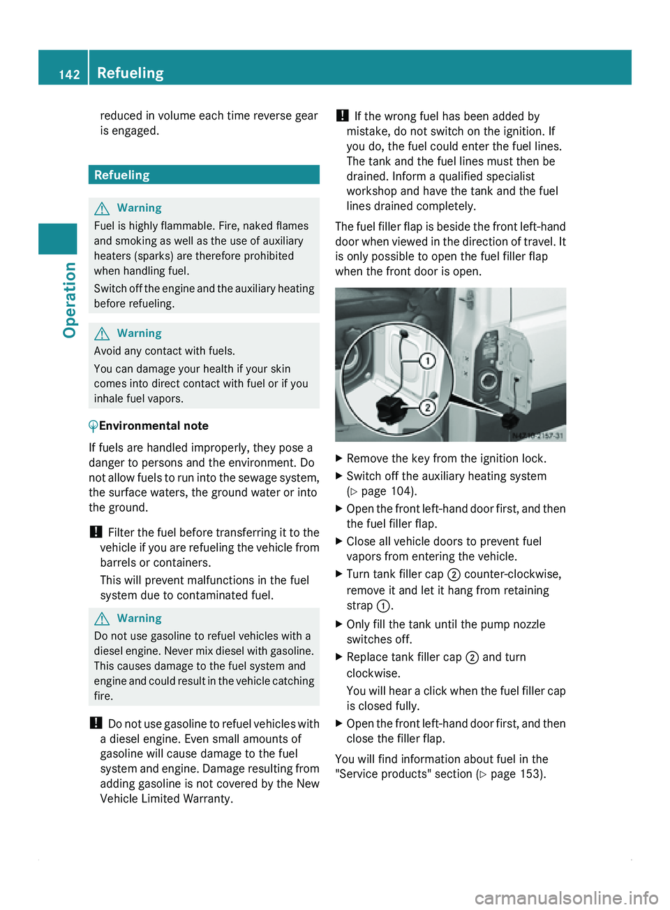
The fuel filler
flap is beside the front left-hand
door when viewed in the direction of travel. It
is only possible to open the fuel filler flap
when the front door is open. X
Remove the key from the ignition lock.
X Switch off the auxiliary heating system
(Y page 104).
X Open the front left-hand door first, and then
the fuel filler flap.
X Close all vehicle doors to prevent fuel
vapors from entering the vehicle.
X Turn tank filler cap 0047 counter-clockwise,
remove it and let it hang from retaining
strap 0046.
X Only fill the tank until the pump nozzle
switches off.
X Replace tank filler cap 0047 and turn
clockwise.
You will
hear
a click when the fuel filler cap
is closed fully.
X Open the front left-hand door first, and then
close the filler flap.
You will find information about fuel in the
"Service products" section (Y page 153). 142
Refueling
Operation
Page 145 of 292
Diesel Exhaust Fluid (DEF)
The exhaust gas aftertreatment requires a
reducing agent, Diesel
Exhaust Fluid (DEF), in
order to function correctly. G
Warning
If you open the DEF reservoir cap at high
temperatures, ammonia vapors could be
released.
Ammonia vapors have
a pungent odor and are
particularly irritating for your skin, respiratory
organs and eyes. This may result in burning
eyes, nose and throat, as well as coughing and
watering eyes.
Do not inhale ammonia vapors. G
Warning
Avoid contact with DEF.
DEF is hazardous
to health. Do not allow DEF
to come into contact with your skin. Rinse
affected areas with plenty of clean water and
consult a doctor if necessary.
0040Environmental note
Dispose of DEF in an environmentally
responsible manner.
! Only use DEF in accordance with
ISO 22241 .
The exhaust gas aftertreatment
system may otherwise be damaged.
Observe the MB Specifications for Service
Products, Sheet No. 352.0.
Damage caused by the use of other
reducing agents will result in the loss of
your New Vehicle Limited Warranty
entitlements.
! If DEF comes into contact with a painted
or aluminum surface, wash the surface off
immediately with plenty of water.
! DEF is not a diesel additive and must not
be mixed with fuel in the tank. Even small
amounts of DEF can cause engine damage.
Damage resulting from adding DEF is not
covered by the New Vehicle Limited
Warranty. i
If the DEF level drops below the reserve
level, the second warning message
(Y page 116) appears and at this point, at
the latest, you
must add at least 2.0 US gal
(7.6 l) of DEF.
You will find further information on DEF in the
"Service products" section (Y page 155).
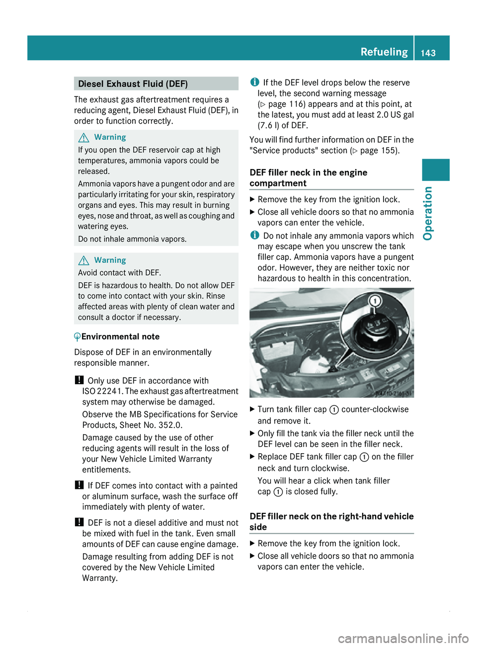
DEF filler neck in the engine
compartment X
Remove the key from the ignition lock.
X Close all
vehicle doors so that no ammonia
vapors can enter the vehicle.
i Do not inhale
any ammonia vapors which
may escape when you unscrew the tank
filler cap. Ammonia vapors have a pungent
odor. However, they are neither toxic nor
hazardous to health in this concentration. X
Turn tank filler cap 0046
counter-clockwise
and remove it.
X Only fill the tank via the filler neck until the
DEF level can be seen in the filler neck.
X Replace DEF tank filler cap 0046 on the filler
neck and turn clockwise.
You will hear a click when tank filler
cap 0046 is closed fully.
DEF filler neck on the right-hand vehicle
side X
Remove the key from the ignition lock.
X Close all vehicle doors so that no ammonia
vapors can enter the vehicle. Refueling
143
Operation Z
Page 146 of 292
i
Do not inhale
any ammonia vapors which
may escape when you unscrew the tank
filler cap. Ammonia vapors have a pungent
odor. However, they are neither toxic nor
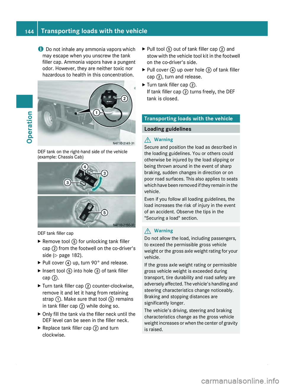
hazardous to health in this concentration. DEF tank on the right-hand side of the vehicle
(example: Chassis Cab)
DEF tank filler cap
X
Remove tool 0086 for unlocking tank filler
cap 0047 from the
footwell on the co-driver's
side ( Y page 182).
X Pull cover 0088 up, turn 90° and release.
X Insert tool 0086 into hole 008A of tank filler
cap 0047.
X Turn tank filler cap 0047 counter-clockwise,
remove it and let it hang from retaining
strap 0046. Make sure that tool 0086 remains
in tank filler cap 0047 while doing so.
X Only fill the tank via the filler neck until the
DEF level can be seen in the filler neck.
X Replace tank filler cap 0047 and turn
clockwise. X
Pull tool 0086 out of tank filler cap 0047 and
stow with
the
vehicle tool kit in the footwell
on the co-driver's side.
X Pull cover 0088 up over hole 008A of tank filler
cap 0047, turn and release.
X Turn tank filler cap 0047.
If tank filler cap 0047 turns freely, the DEF
tank is closed. Transporting loads with the vehicle
Loading guidelines
G
Warning
Secure and position the load as described in
the loading guidelines. You or others could
otherwise be injured by the load slipping or
being thrown around in the event of sharp
braking, sudden changes in direction or on
poor road surfaces.
This also applies to seats
which have been removed if they remain in the
vehicle.
Even if you follow all loading guidelines, the
load increases the risk of injury in the event
of an accident. Observe the tips in the
"Securing a load" section. G
Warning
Do not allow the load, including passengers,
to exceed the permissible gross vehicle
weight or the
gross axle weight rating for your
vehicle.
If the gross axle weight rating or permissible
gross vehicle weight is exceeded during
transport, tire durability and road safety are
adversely affected. The vehicle's handling and
steering characteristics change noticeably.
Braking and stopping distances are
significantly longer.
The vehicle's driving, steering and braking
characteristics change as the gross vehicle
weight increases or when the center of gravity
is raised. 144
Transporting loads with the vehicle
Operation
Page 172 of 292
Only open the coolant expansion tank when
the coolant temperature is below 122 ‡
(50 †).
G
Warning
Coolant contains glycol and is therefore toxic.
Do not swallow the coolant. See a doctor
immediately if you swallow coolant.
Make sure that coolant does not come into
contact with skin,
eyes or clothing. In case of
contact with eyes, rinse immediately with
plenty of clean water. Clean affected areas of
skin and clothing with soap and water
immediately. Change any affected clothing
immediately.
X Slowly turn cap 0046 counter-clockwise and
allow the excess pressure to escape.
X Turn cap 0046 further and remove it.
X Add coolant until it is at the MAX mark.
Observe the correct coolant mixture ratio
and the required water quality
(Y page 160).
X Replace cap 0046 and tighten
it until the stop.
! Check the cooling and heating system
regularly for leaks.
If a large quantity of coolant is lost, have
the cause traced
and rectified at a qualified
specialist workshop, e.g. an authorized
Sprinter Dealer. Clutch mechanism and brake system
G
Warning
Brake fluid is hazardous to health. Do not
swallow brake fluid.
See a doctor immediately
if you swallow brake fluid.
Make sure that brake fluid does not come into
contact with skin, clothing or eyes. Rinse
affected areas with plenty of clean water and
consult a doctor if necessary.
Always wear gloves and eye protection when
topping up brake fluid. Store brake fluid only in the original closed
container and keep it out of the reach of
children. Comply with safety regulations
when handling brake fluid.
G
Warning
If the
boiling point of the brake fluid is too low,
vapor pockets may form in the brake system
when the brakes
are subjected to a heavy load
(e.g. on long downhill stretches). This would
impair braking efficiency. The vehicle's
stopping distance may then be longer. This
increases the risk of an accident.
Have the brake fluid renewed every two years.
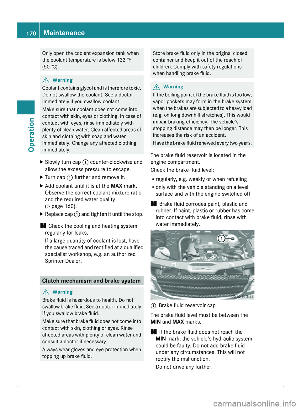
The brake fluid reservoir is located in the
engine compartment.
Check the brake fluid level:
R regularly, e.g. weekly or when refueling
R only with the vehicle standing on a level
surface and with the engine switched off
! Brake fluid corrodes paint, plastic and
rubber. If paint, plastic or rubber has come
into contact with brake fluid, rinse with
water immediately. 0046
Brake fluid reservoir cap
The brake fluid level must be between the
MIN and
MAX marks.
! If the brake fluid does not reach the
MIN mark, the vehicle's hydraulic system
could be faulty. Do not add brake fluid
under any circumstances. This will not
rectify the malfunction.
Do not drive any further. 170
Maintenance
Operation
Page 184 of 292
Vehicle equipment
i Diese Betriebsanleitung beschreibt alle
Modelle, Serien- und
Sonderausstattungen
Ihres Fahrzeugs, die zum Zeitpunkt des
Redaktionsschlusses dieser
Betriebsanleitung erhältlich waren.
Länderspezifische Abweichungen sind
möglich. Beachten Sie, dass Ihr Fahrzeug
nicht mit allen beschriebenen Funktionen
ausgestattet sein könnte. Dies betrifft auch
sicherheitsrelevante Systeme und
Funktionen. Where will I find...?
Vehicle tool kit and emergency
equipment
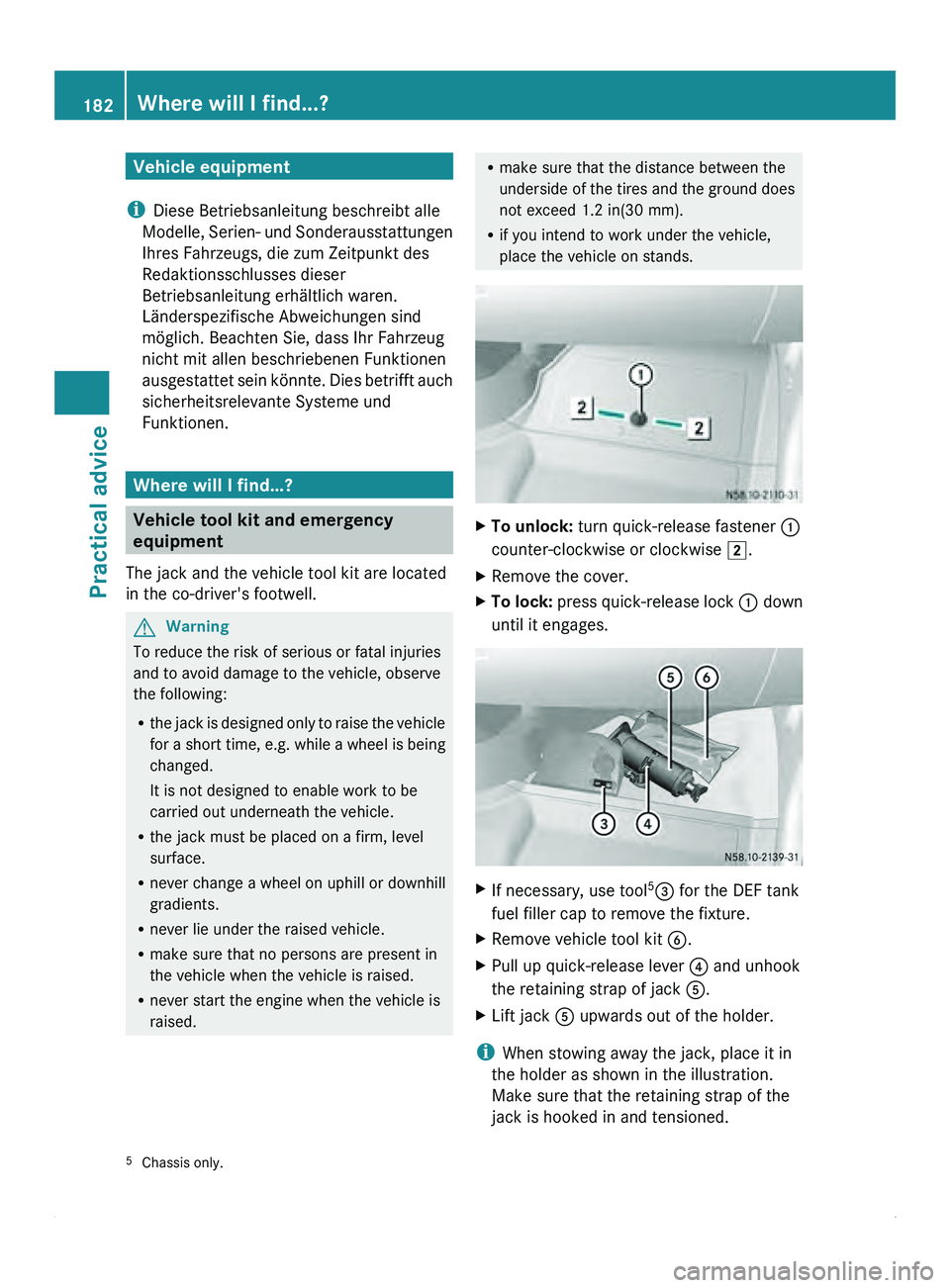
The jack and the vehicle tool kit are located
in the co-driver's footwell. G
Warning
To reduce the risk of serious or fatal injuries
and to avoid damage to the vehicle, observe
the following:
R the jack is
designed only to raise the vehicle
for a short time, e.g. while a wheel is being
changed.
It is not designed to enable work to be
carried out underneath the vehicle.
R the jack must be placed on a firm, level
surface.
R never change a wheel on uphill or downhill
gradients.
R never lie under the raised vehicle.
R make sure that no persons are present in
the vehicle when the vehicle is raised.
R never start the engine when the vehicle is
raised. R
make sure that the distance between the
underside
of the
tires and the ground does
not exceed 1.2 in(30 mm).
R if you intend to work under the vehicle,
place the vehicle on stands. X
To unlock: turn quick-release fastener
0046
counter-clockwise or clockwise 004B.
X Remove the cover.
X To lock: press quick-release lock
0046 down
until it engages. X
If necessary, use tool 5
008A for the DEF tank
fuel filler cap to remove the fixture.
X Remove vehicle tool kit 0087.
X Pull up quick-release lever 0088 and unhook
the retaining strap of jack 0086.
X Lift jack 0086 upwards out of the holder.
i When stowing away the jack, place it in
the holder as shown in the illustration.
Make sure that the retaining strap of the
jack is hooked in and tensioned.
5 Chassis only.182
Where will I find...?
Practical advice
Page 187 of 292
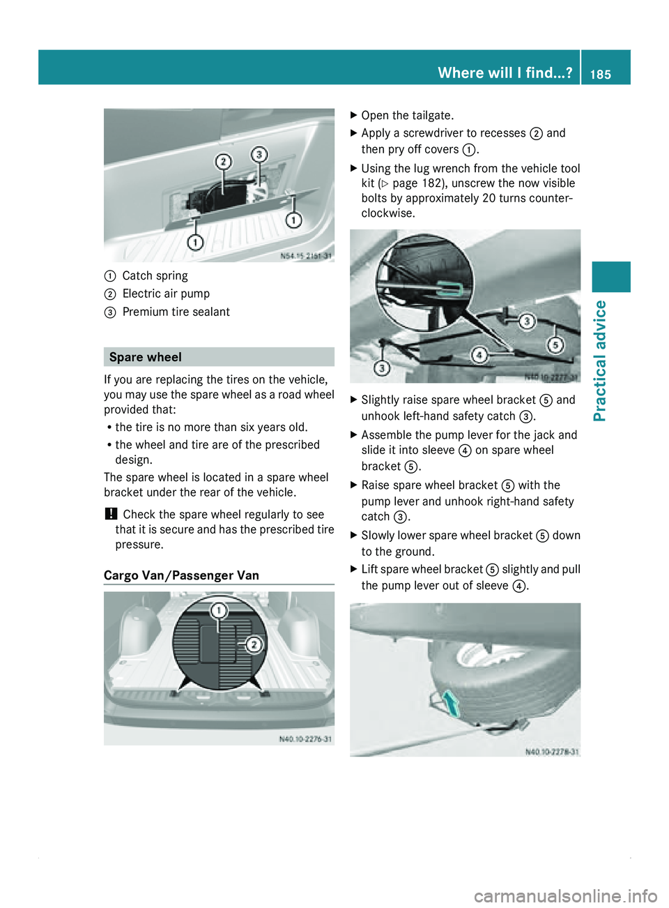
0046
Catch spring
0047 Electric air pump
008A Premium tire sealant Spare wheel
If you are replacing the tires on the vehicle,
you may use
the spare wheel as a road wheel
provided that:
R the tire is no more than six years old.
R the wheel and tire are of the prescribed
design.
The spare wheel is located in a spare wheel
bracket under the rear of the vehicle.
! Check the spare wheel regularly to see
that it is secure and has the prescribed tire
pressure.
Cargo Van/Passenger Van X
Open the tailgate.
X Apply a screwdriver to recesses 0047 and
then pry off covers 0046.
X Using the lug wrench from the vehicle tool
kit ( Y page 182), unscrew the now visible
bolts by approximately 20 turns counter-
clockwise. X
Slightly raise spare wheel bracket 0086 and
unhook left-hand safety catch 008A.
X Assemble the pump lever for the jack and
slide it into sleeve 0088 on spare wheel
bracket 0086.
X Raise spare wheel bracket 0086 with the
pump lever and unhook right-hand safety
catch 008A.
X Slowly lower spare wheel bracket 0086 down
to the ground.
X Lift spare
wheel bracket 0086 slightly and
pull
the pump lever out of sleeve 0088. Where will I find...?
185
Practical advice Z
Page 226 of 292
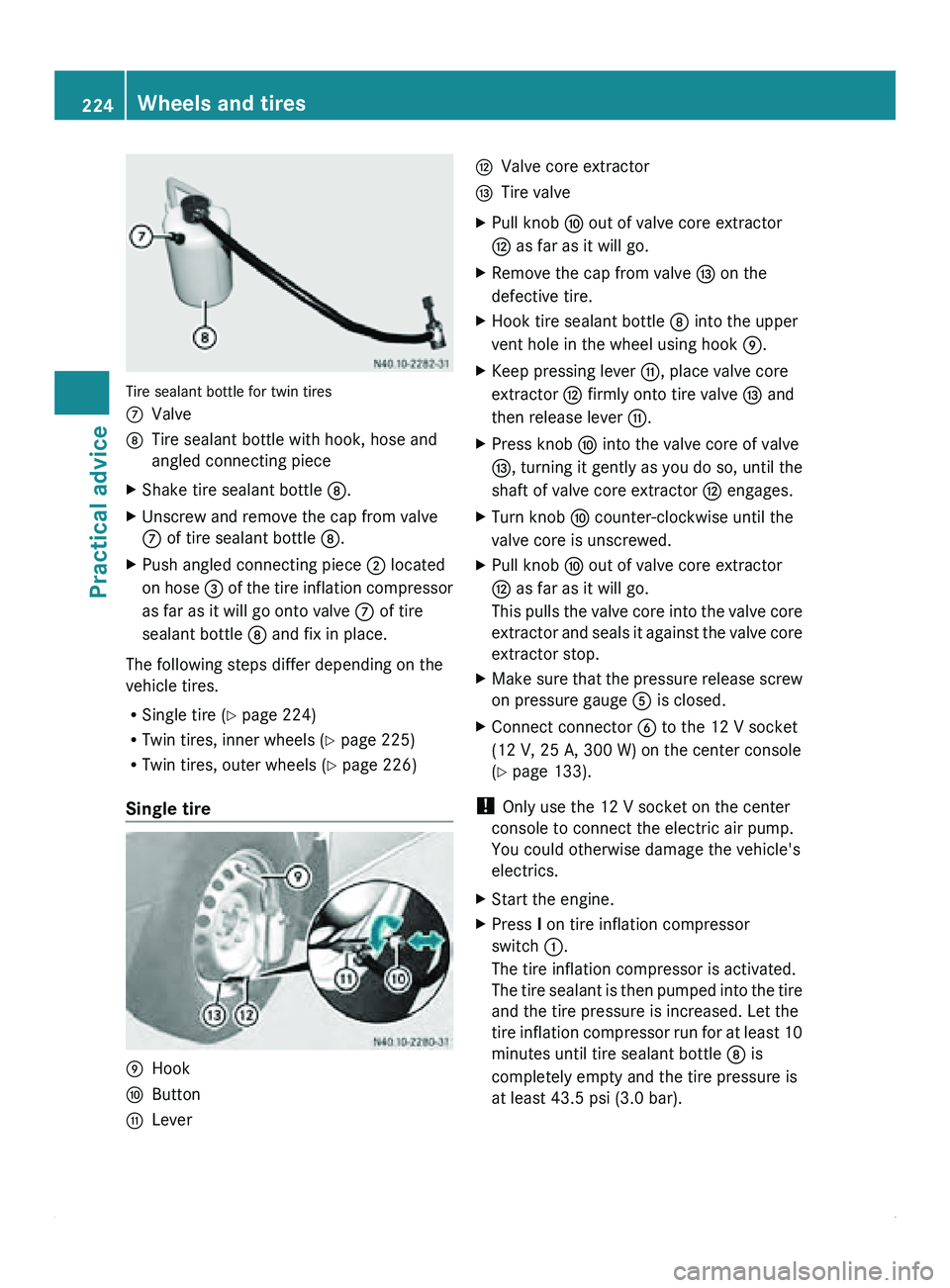
Tire sealant bottle for twin tires
006E
Valve
006F Tire sealant bottle with hook, hose and
angled connecting piece
X Shake tire sealant bottle 006F.
X Unscrew and remove the cap from valve
006E of tire sealant bottle 006F.
X Push angled connecting piece 0047 located
on hose 008A
of the tire inflation compressor
as far as it will go onto valve 006E of tire
sealant bottle 006F and fix in place.
The following steps differ depending on the
vehicle tires.
R Single tire (Y page 224)
R Twin tires, inner wheels ( Y page 225)
R Twin tires, outer wheels (
Y page 226)
Single tire 0070
Hook
0071 Button
0072 Lever 0073
Valve core extractor
0074 Tire valve
X Pull knob 0071 out of valve core extractor
0073 as far as it will go.
X Remove the cap from valve 0074 on the
defective tire.
X Hook tire sealant bottle 006F into the upper
vent hole in the wheel using hook 0070.
X Keep pressing lever 0072, place valve core
extractor 0073 firmly onto tire valve 0074 and
then release lever 0072.
X Press knob 0071 into the valve core of valve
0074, turning it gently as you do so, until the
shaft of valve core extractor 0073 engages.
X Turn knob 0071 counter-clockwise until the
valve core is unscrewed.
X Pull knob 0071 out of valve core extractor
0073 as far as it will go.
This pulls
the
valve core into the valve core
extractor and seals it against the valve core
extractor stop.
X Make sure that the pressure release screw
on pressure gauge 0086 is closed.
X Connect connector 0087 to the 12 V socket
(12 V, 25 A, 300 W) on the center console
(Y page 133).
! Only use the 12 V socket on the center
console to connect the electric air pump.
You could otherwise damage the vehicle's
electrics.
X Start the engine.
X Press I on tire inflation compressor
switch 0046.
The tire inflation compressor is activated.
The tire sealant
is then pumped into the tire
and the tire pressure is increased. Let the
tire inflation compressor run for at least 10
minutes until tire sealant bottle 006F is
completely empty and the tire pressure is
at least 43.5 psi (3.0 bar). 224
Wheels and tires
Practical advice
Page 227 of 292
!
Do not run
the electric air pump for longer
than 20 minutes without a break; otherwise
it may overheat.
The air pump can be used again once it has
cooled down.
X Inflate the tire using the tire inflation
compressor until the recommended tire
pressure ( Y page 281) is reached.
X Then, press 0 on tire inflation compressor
switch 0046.
The tire inflation compressor is
deactivated.
X Slide knob 0071 quickly to the stop in valve
core extractor 0073.
X Turn knob 0071 clockwise
until
the valve core
is firmly screwed into tire valve 0074.
i Do not pull the valve core extractor from
the tire valve while the valve core is
unscrewed from
the
tire valve. Tire sealant
could otherwise escape and make you
dirty.
The tire sealant is water-soluble. If tire
sealant escapes, you can wash it away with
water.
X Press lever 0072 and pull
valve core extractor
0073 from tire valve 0074.
X Screw the valve cap onto tire valve 0074.
After filling with tire sealant, ( Y page 228).
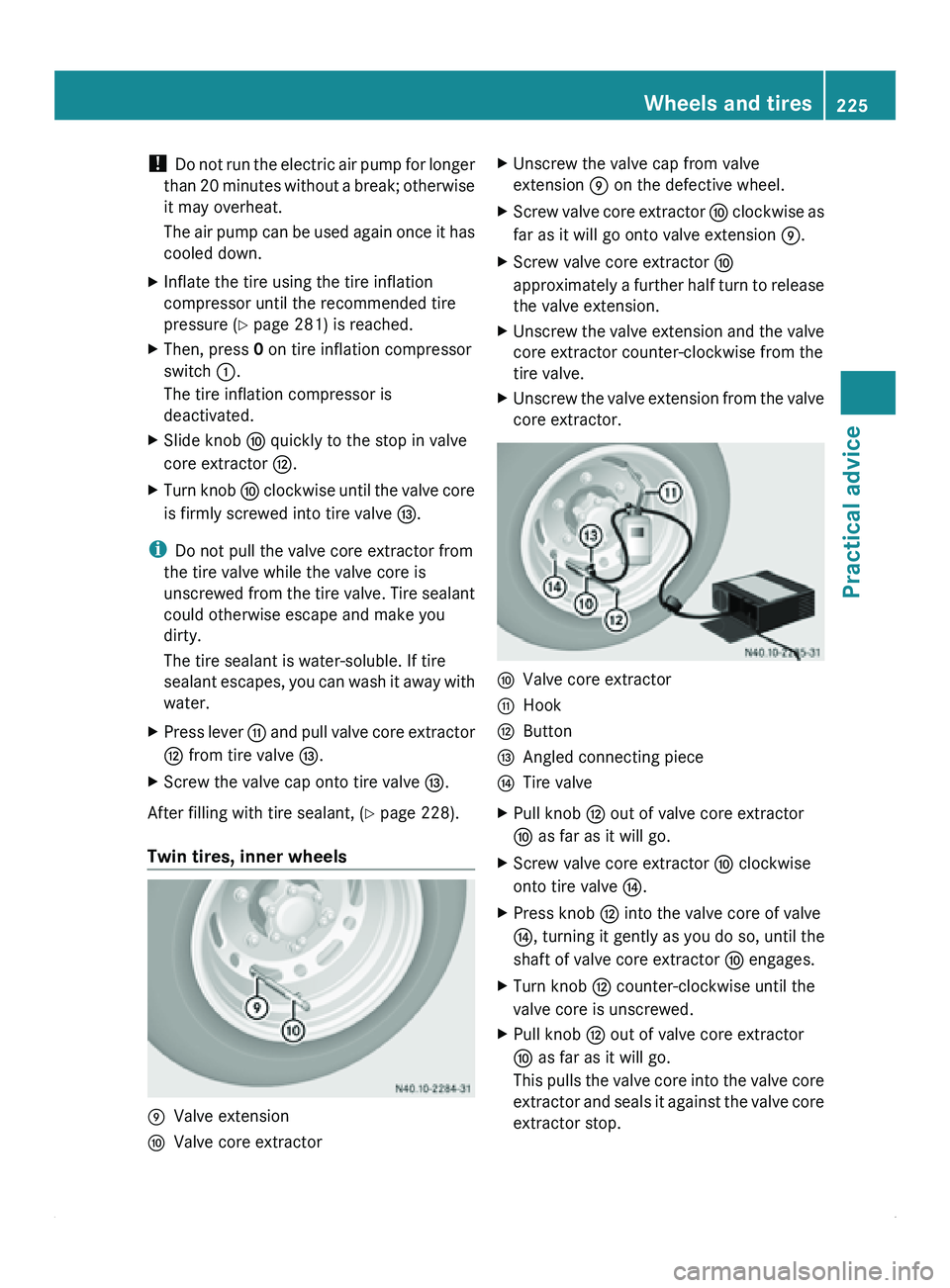
Twin tires, inner wheels 0070
Valve extension
0071 Valve core extractor X
Unscrew the valve cap from valve
extension 0070 on the defective wheel.
X Screw valve core extractor 0071
clockwise as
far as it will go onto valve extension 0070
.
X Screw valve core extractor 0071
approximately a
further
half turn to release
the valve extension.
X Unscrew the valve extension and the valve
core extractor counter-clockwise from the
tire valve.
X Unscrew the valve extension from the valve
core extractor. 0071
Valve core extractor
0072 Hook
0073 Button
0074 Angled connecting piece
0075 Tire valve
X Pull knob 0073 out of valve core extractor
0071 as far as it will go.
X Screw valve core extractor 0071 clockwise
onto tire valve 0075.
X Press knob 0073 into the valve core of valve
0075, turning it gently as you do so, until the
shaft of valve core extractor 0071 engages.
X Turn knob 0073 counter-clockwise until the
valve core is unscrewed.
X Pull knob 0073 out of valve core extractor
0071 as far as it will go.
This pulls
the
valve core into the valve core
extractor and seals it against the valve core
extractor stop. Wheels and tires
225
Practical advice Z
Page 228 of 292
X
Hook tire sealant bottle 006F into the upper
vent hole in the wheel using hook 0072.
X Push angled connecting piece 0074 located
on the hose of tire sealant filler bottle 006F
as far
as
it will go on to valve core extractor
0071 and fix it in place.
X Make sure that the pressure release screw
on pressure gauge 0086 is closed.
X Connect connector 0087 to the 12 V socket
(12 V, 25 A, 300 W) on the center console
(Y page 133).
! Only use the 12 V socket on the center
console to connect the electric air pump.
You could otherwise damage the vehicle's
electrics.
X Start the engine.
X Press I on tire inflation compressor
switch 0046.
The tire inflation compressor is activated.
The tire
sealant
is then pumped into the tire
and the tire pressure is increased. Let the
tire inflation compressor run for at least 10
minutes until tire sealant bottle 006F is
completely empty and the tire pressure is
at least 43.5 psi (3.0 bar).
! Do not
run
the electric air pump for longer
than 20 minutes without a break; otherwise
it may overheat.
The air pump can be used again once it has
cooled down.
X Inflate the tire using the tire inflation
compressor until the recommended tire
pressure ( Y page 281) is reached.
X Then, press 0 on tire inflation compressor
switch 0046.
The tire inflation compressor is
deactivated.
X Slide knob 0073 quickly to the stop in valve
core extractor 0071.
X Turn knob 0073 clockwise
until
the valve core
is firmly screwed into tire valve 0075.i
Do not pull the valve core extractor from
the tire valve while the valve core is
unscrewed from the
tire valve. Tire sealant
could otherwise escape and make you
dirty.
The tire sealant is water-soluble. If tire
sealant escapes, you can wash it away with
water.
X Pull knob 0073 out of valve core extractor
0071 as far as it will go.
X Unscrew valve core extractor 0071 counter-
clockwise from tire valve 0075.
X Screw valve extension 0070 onto tire valve
0075 and tighten it.
X Screw the valve cap onto valve extension
0070.
After filling with tire sealant, ( Y page 228).
Twin tires, outer wheel The tire valve is located on the inside of the
outer wheel and should be positioned
horizontally on the left side of the wheel for
the repair process.
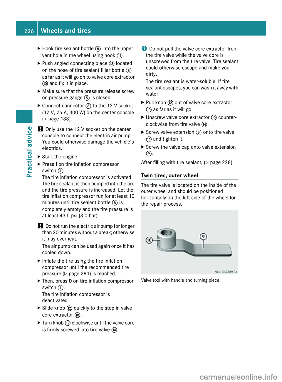
Valve tool with handle and turning piece226
Wheels and tires
Practical advice
Page 230 of 292
i
If the valve
insert is damaged or lost when
it is unscrewed, you can use the valve insert
of the tire sealant bottle after you have
used the tire sealant.
X Unscrew the valve insert from the valve of
the tire sealant bottle using the valve
extractor.
! Do not run
the electric air pump for longer
than 20 minutes without a break; otherwise
it may overheat.
The air pump can be used again once it has
cooled down.
X Push angled connecting piece 0047 located
on tire inflation
compressor hose 008A as far
as it will go onto valve 0072 and fix it in place.
X Push I on tire inflation compressor
switch 0046 and inflate the tire to the
recommended tire pressure ( Y page 281).
X Then, press 0 on tire inflation compressor
switch 0046.
The tire inflation compressor is
deactivated.
i The tire sealant is water-soluble. If tire
sealant escapes,
you
can wash it away with
water.
X Screw the valve cap onto tire valve 0072.
After filling with tire sealant, ( Y page 228).
After filling with tire sealant X
Turn the pressure release screw on
pressure gauge 0086 counter-clockwise and
bleed the system.
X Turn the key to position 0 in the ignition
lock.
X Pull the tire inflation compressor connector
out of the 12 V socket.
X Stow the tire inflation compressor, tire
sealant bottle 006F with the valve core
extractor and/or valve tool, the warning triangle and hazard warning lights inside
the vehicle.
X Remove angled connecting piece 0047 from
valve 006E of tire sealant filler bottle 006F and
screw the valve cap onto the valve. G
Warning
You must not exceed a maximum speed of
50 mph (80 km/h) .
The "max.
50 mph" (80 km/h) sticker must be
affixed within the driver's field of vision.
The vehicle's handling characteristics may be
affected.
X Pull away immediately.
This enables the tire sealant to distribute
inside the tire and create a more effective
seal.
X Stop after driving for about three minutes
and check the tire pressure using the tire
inflation compressor, for example.
i You must connect the angled connecting
piece on hose 008A of the tire inflation
compressor directly to
the tire valve on the
tire.
X Correct the tire pressure accordingly if it
does not correspond to the recommended
tire pressure ( Y page 281).
X To increase the tire pressure: switch on
the tire inflation compressor.
X To reduce the tire pressure: open the
pressure release screw on pressure
gauge 0086.
X Drive to the nearest workshop and have the
tire repaired or replaced.
X Clean the valve core extractor with clean
water.
X Have tire sealant bottle 006F replaced as
soon as possible at a qualified specialist
workshop, e.g. an authorized Sprinter
Dealer.228
Wheels and tires
Practical advice