radio MERCEDES-BENZ SPRINTER 2017 MY17 Operator’s Manual
[x] Cancel search | Manufacturer: MERCEDES-BENZ, Model Year: 2017, Model line: SPRINTER, Model: MERCEDES-BENZ SPRINTER 2017Pages: 286, PDF Size: 4.36 MB
Page 13 of 286
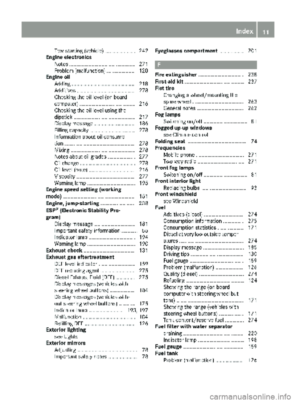
Tow-starting (vehicle) ..................... 242
Engine electronics
Notes ............................................. 271
Problem (malfunction) ...................1 20
Engine oil
Adding ...........................................2 18
Additives ........................................ 278
Checking the oil level (on-board
computer) ...................................... 216
Checking the oil level using the
dipstick .......................................... 217
Display message ............................ 186
Filling capacity ............................... 278
Information about oil consump-
tion ................................................ 278
Mixing ............................................ 278
Notes about oil grades ................... 277
Oil change ...................................... 278
Oil level (note) ............................... 216
Viscosity ........................................ 277
Warning lamp ................................. 195
Engine speed setting (working
mode) ................................................. 151
Engine, jump-starting ....................... 238
ESP
®(Electronic Stability Pro-
gram)
Display message ............................ 181
Important safety information ........... 55
Indicator lamp ................................ 194
Warning lamp ................................. 190
Exhaust check ................................... 131
Exhaust gas aftertreatment
DEF level indicator ......................... 159
DEF reducing agent ....................... 275
Diesel Exhaust Fluid (DEF) ............. 275
Display messages (vehicles with
steering wheel buttons) ................. 184
Display messages (vehicles with-
out steering wheel buttons) ........... 175
Indicator lamp ....................... 193, 197
Malfunction ....................................1 84
Refilling DEF .................................. 126
Exterior lighting
see Lights
Exterior mirrors
Adjusting ......................................... 78
Important safety notes .................... 78 Eyegl
asses compartment
................. 201
F
Fire extinguisher............................... 238
First-aid kit ......................................... 237
Flat tire
Changing a wheel/mounting the
spare wheel ................................... 263
General notes ................................ 262
Fog lamps
Switching on/off .............................. 81
Fogged up-up windows
see Climate control
Folding seat ......................................... 74
Frequencies
Mobile phone ................................. 271
Two-way radio ................................ 271
Front fog lamps
Switching on/off .............................. 81
Front interior light
Replacing bulbs ............................... 93
Front windshield
see Windshield
Fuel
Additives (diesel) ........................... 274
Consumption information .............. 275
Consumption statistics .................. 171
Diesel at very low outside temper-atures ............................................ 274
Display message ............................ 185
Driving tips ....................................1 30
Fuel gauge ..................................... 159
Problem (malfunction) ................... 126
Quality (diesel) ............................... 274
Refueling ........................................ 124
Showing the range (on-board
computer with steering wheel but-
tons) .............................................. 171
Showing the range (vehicles with
steering wheel buttons) ................. 171
Tank content/reserve fuel ............. 274
Fuel filter with water separator
draining ......................................... 220
Indicator lamp ................................ 198
Fuel gauge ......................................... 159
Fuel tank
Problem (malfunction) ................... 126
Index11
Page 18 of 286
R
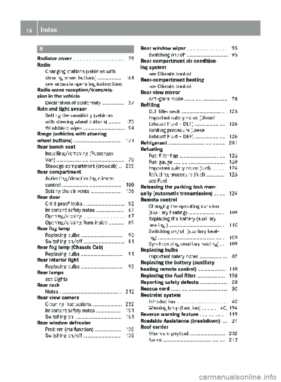
Radiator cover..................................... 29
Radio
Changing stations (vehicles with
steering wheel buttons) ................. 164
see separate operating instructions
Radio-wave reception/transmis-
sion in the vehicle
Declaration of conformity ................ 27
Rain and light sensor
Setting the sensitivity (vehicles
with steering wheel buttons) ......... 170
Windshield wiper .............................. 94
Range (vehicles with steering
wheel buttons) .................................. 171
Rear bench seat
Installing/removing (Passenger
Van) ................................................. 75
Stowage compartment (crewcab) .. 203
Rear compartment
Activating/deactivating climate
control ........................................... 100
Setting the air vents ...................... 105
Rear door
Child-proof locks .............................. 52
Important safety notes .................... 67
Opening/closing .............................. 67
Opening/closing from inside ........... 69
Rear fog lamp
Replacing bulbs ............................... 90
Switching on/off .............................. 81
Rear fog lamp (Chassis Cab)
Replacing bulbs ............................... 91
Rear interior light
Replacing bulbs ............................... 93
Rear lamps
see Lights
Rear rack
Notes ............................................. 212
Rear view camera
Cleaning instructions ..................... 232
Important safety notes .................. 151
Switching on .................................. 151
Rear window defroster
Problem (malfunction) ................... 103
Switching on/off ........................... 103 Rear window wiper
............................. 95
Switching on/off .............................. 95
Rear-compartment air-condition-
ing system
see Climate control
Rear-compartment heating
see Climate control
Rear-view mirror
Anti-glare mode ............................... 78
Refilling
DEF filler neck ............................... 126
Important safety notes (Diesel
Exhaust Fluid – DEF) ...................... 126
Refilling procedure (Diesel
Exhaust Flu id – DEF) ...................... 126
Re
frigerant ......................................... 281
Refueling
Fuel filler flap ................................. 125
Fuel gauge ..................................... 159
Important safety notes (fuel) ......... 124
Refueling procedure (fuel) ............. 125
see Fuel
Releasing the parking lock man-
ually (automatic transmission) ........ 124
Remote control
Changing the operating duration
(auxiliary heating) .......................... 109
Replacing the battery (auxiliary
heating ) ........................................ 110
Switching on/off (auxiliary heat-
ing) ................................................ 109
Synchronizing (auxiliary heating) ... 109
Replacing bulbs
Important safety notes .................... 87
Replacing the battery (auxiliary
heating remote control) .................... 110
Replacing the fuel filter .................... 198
Reporting safety defects .................... 28
Rescue card ......................................... 30
Restraint system
Introduction ..................................... 40
Warning lamp (function) .......... 40, 194
Reverse warning feature .................. 119
Roadside Assistance (breakdown) .... 24
Roof carrier
Maximum payload .......................... 282
Notes ............................................. 212
16Index
Page 20 of 286
Checking the battery .......................61
Display message ............................ 189
Door central locking/unlocking ....... 59
Important safety notes .................... 59
Loss ................................................. 62
Problem (malfunction) ..................... 62
SmartKey positions (ignition lock) .. 117
Snow chains ...................................... 246
Sockets .............................................. 206
Spare wheel
General notes ................................ 268
Important safety notes .................. 268
Removing/mounting ...................... 269
Special seat belt retractor .................. 48
Specialist workshop ............................ 27
Speed, controlling
see Cruise control
Speedometer
Digital (vehicles with steering
wheel buttons) ............................... 167
Digital (vehicles without steering
wheel buttons) ............................... 160
Selecting display unit (vehicles
with steering- wheel buttons) ........ 167
see Instrument cluster
Sprinter dealer
see Qualified specialist workshop
Standing lamps
Replacing bulbs ............................... 88
Replacing bulbs (rear) ...................... 90
Standing lamps (Chassis Cab)
Replacing bulbs (rear) ...................... 91
Start-off assist
Display message ............................ 179
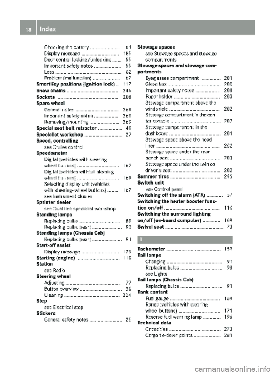
Starting (engine) ................................ 118
Station
see Radio
Steering wheel
Adjusting ......................................... 77
Button overview ............................... 36
Cleaning ......................................... 234
Step
see Electrical step
Stickers
General safety notes ........................ 25 Stowage spaces
see Stowage spaces and stowage
compartments
Stowage spaces and stowage com-
partments
Eyeglasses compartment ............... 201
Glove box ....................................... 200
Important safety notes .................. 200
Paper holder .................................. 203
Stowage co
mpartment above the
windshield ..................................... 202
Stowage compartment in the cen-
ter console ..................................... 202
Stowage compartment in the
dashboard ...................................... 201
Stowage space above the head-
liner ............................................... 202
Stowage space under the rear
bench seat ..................................... 203
Stowage space under the twin co-
driver's seat ................................... 202
Summer tires ..................................... 245
Switch unit
see Control panel
Switching off the alarm (ATA) ............ 57
Switching the heater booster func-
tion on/off ......................................... 110
Switching the surround lighting
on/off (on-board computer) ............. 169
Swivel seat ........................................... 73
T
Tachometer ........................................ 159
Tail lamps
Changing ......................................... 91
Replacing bulbs ............................... 90
see Lights
Tail lamps (Chassis Cab)
Replacing bulbs ............................... 91
Tank content
Fuel gauge ..................................... 159
Range (vehicles with steering
wheel buttons) ............................... 171
Reserve fuel warning lamp ............. 196
Technical data
Capacities ...................................... 273
Cargo tie-down points .................... 281
18Index
Page 23 of 286
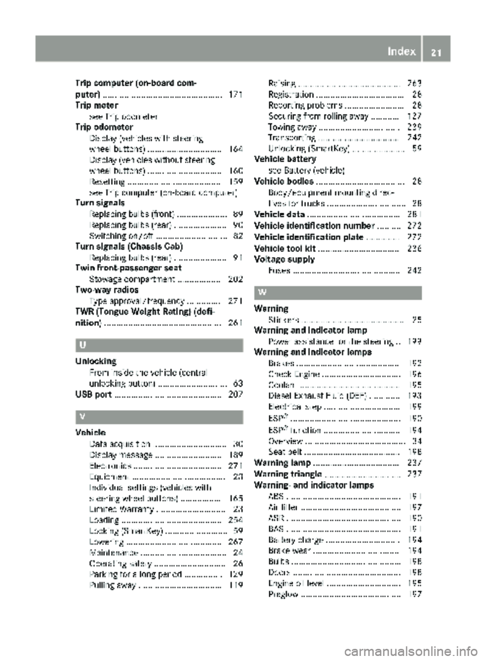
Trip computer (on-board com-
puter).................................................. 171
Trip meter
see Trip odometer
Trip odometer
Display (vehicles with steering
wheel buttons) ............................... 164
Display (vehicles without steering
wheel buttons) ............................... 160
Resetting ....................................... 159
see Trip computer (on-board computer)
Turn signals
Replacing bulbs (front) ..................... 89
Replacing bulbs (rear) ...................... 90
Switching on/off .............................. 82
Turn signals (Chassis Cab)
Replacing bulbs (rear) ...................... 91
Twin front-passenger seat
Stowage compartment .................. 202
Two-way radios
Type approval/frequency .............. 271
TWR (Tongue Weight Rating) (defi-
nition) ................................................. 261
U
Unlocking
From inside the vehicle (central
unlocking button) ............................. 63
USB port ............................................. 207
V
Vehicle
Data acquisition ............................... 30
Display message ............................ 189
Electronics ..................................... 271
Equipment ....................................... 23
Individual settings (vehicles with
steering wheel buttons) ................. 165
Limited Warranty ............................. 23
Loading .......................................... 254
Locking (SmartKey) .......................... 59
Lowering ........................................ 267
Maintenance .................................... 24
Operating safety .............................. 26
Parking for a long period ................ 129
Pulling away ................................... 119 Raising ........................................... 263
Registration ..................................... 28
Reporting problems ......................... 28
Securing from rolling away ............ 127
Towing away .................................. 239
Transporting .................................. 242
Unlocking (SmartKey) ...................... 59
Vehicle battery
see Battery (vehicle)
Vehicle bodies ..................................... 28
Body/equipment mounting direc-
tives for trucks ................................. 28
Vehicle data ....................................... 281
Vehicle identification number .......... 272
Vehicle identification plate .............. 272
Vehicle tool kit .................................. 236
Voltage supply
Fuses ............................................. 242
W
WarningStickers ........................................... 25
Warning and indicator lamp
Power assistance for the steering .. 199
Warning and indicator lamps
Brakes ........................................... 192
Check Engine ................................. 196
Coolant .......................................... 195
Diesel Exhaust Fluid (DEF) ............. 193
Electrical step ................................ 199
ESP
®.............................................. 190
ESP®function ................................ 194
Overview .......................................... 34
Seat belt ........................................ 198
Warning lamp .................................... 237
Warning triangle ................................ 237
Warning- and indicator lamps
ABS ................................................ 191
Air filter .......................................... 197
ASR ................................................ 190
BAS ................................................ 191
Battery charge ............................... 194
Brake wear .................................... 194
Bulbs .............................................. 198
Doors ............................................. 198
Engine oil level ............................... 195
Preglow .......................................... 197
Index21
Page 29 of 286
When driving off road or on unpaved roads,
check the vehicle's underside regularly. In
particular, remove parts of plants or other
flammable materials which have become
trapped. In the case of damage, contact a
qualified specialist workshop.
Have the vehicle checked and repaired immedi-
ately at a qualified specialist workshop. If you
become aware when continuing the journey that
driving safety has been effected, stop as soon as
possible in accordance with the traffic condi-
tions. In such cases, consult a qualified special- ist workshop.
Declaration of conformity
Radio-based vehicle components
USA: "The wireless devices of this vehicle com-
ply with Part 15 of the FCC Rules. Operation is
subject to the following two conditions: 1) These
devices may not cause harmful interference. 2.
This device must accept any interference
received, including interference that may cause
undesired operation. Changes or modifications
not expressly approved by the party responsible
for compliance could void the user’s authority to
operate the equipment."
Canada: "The wireless devices of this vehicle
comply with Industry Canada license-exempt
RSS standard(s). Operation is subject to the fol-
lowing two conditions: 1) These devices may not
cause interference, and 2) these devices must
accept any interference received, including
interference that may cause undesired opera-
tion of the device".
Diagnostics connection
The diagnostics connection is only intended for the connection of diagnostic equipment at a
qualified specialist workshop.
GWARNING
If you connect equipment to a diagnostics
connection in the vehicle, it may affect the
operation of vehicle systems. As a result, the
operating safety of the vehicle could be affec-
ted. There is a risk of an accident.
Only connect equipment to a diagnostics con-
nection in the vehicle, which is approved for
your vehicle by Mercedes-Benz.
Changing the engine power output
!
Increases in engine power can:
Rchange the emission values
Rcause malfunctions
Rcause consequential damage
The operating reliability of the engine is not
guaranteed in all cases.
Any tampering with the engine management
system in order to increase the engine power
output will lead to the loss of the New Vehicle
Limited Warranty and other warranty entitle-
ments.
If you sell the vehicle, inform the purchaser
about the changes to the engine power output of
the vehicle. If you do not inform the buyer, this
may constitute a punishable offense under
national legislation.
Qualified specialist workshops
An authorized Sprinter Dealer is a qualified spe-
cialist workshop.
A qualified specialist workshop has the neces-
sary specialist knowledge, tools and qualifica-
tions to correctly carry out the work required on
the vehicle.
This is especially the case for work relevant to
safety. Observe the notes in the Maintenance or
Service Booklet.
The following work should always be carried out
at qualified specialist workshop:
Rwork relevant to safety
Rservice and maintenance work
Rrepair work
Rmodifications as well as installations and
alterations
Rwork on electronic components
For this reason, we recommend an authorized
Sprinter Dealer.
!Only have work carried out on the engine
electronics and its associated parts, such as
control units, sensors, actuating components
and connector leads, at a qualified specialist
Introduction27
Z
Page 119 of 286
the battery main switch. You could otherwise
damage components of the electrical system.
You can use the battery isolating switch to dis-
connect the power supply to all your vehicle's
consumers. This will prevent uncontrolled bat-
tery discharge caused by off-load current con-
sumption.
If your vehicle is equipped with an auxiliary bat-
tery in the engine compartment, you will need to
disconnect both batteries. Only then is the elec- trical system fully disconnected from the power
supply.
iOnly switch the vehicle to de-energized
using the battery main switch if:
Rthe vehicle is stationary for a lengthy period
Rit is absolutely necessary
After the power supply has been activated,
you will need to reset the side windows
(
Ypage 71).
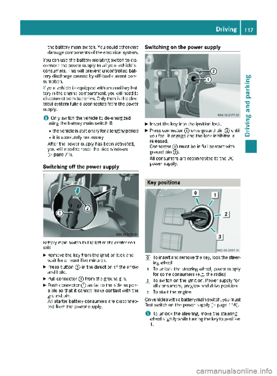
Switching off the power supply
Battery main switch to the left of the center con-
sole
XRemove the key from the ignition lock and
wait for at least five minutes.
XPress button ;in the direction of the arrow
and hold.
XPull connector :from the ground pin.
XPush connector :as far to the side as pos-
sible so that it cannot make contact with the
ground pin.
All starter battery consumers are disconnec-
ted from the power supply.
Switching on the power supply
XInsert the key into the ignition lock.
XPress connector :onto ground pin ;until
you feel it engage and the lock inhibitor is
released.
Connector :must be in full contact with
ground pin ;.
All consumers are reconnected to the DC
power supply.
Key positions
gTo insert and remove the key, lock the steer-
ing wheel
1To unlock the steering wheel, power supply
for some consumers (e.g. the radio)
2To switch on the ignition. Power supply for
all consumers, preglow and drive position
3To start the engine
On vehicles with a battery main switch, you must
first switch on the power supply (
Ypage 116).
iTo unlock the steering, move the steering
wheel slightly while turning the key to position
1 .
Driving117
Dr iving an d parking
Z
Page 153 of 286
Problems with PARKTRONIC
ProblemPossible causes/consequences andMSolutions
Only the red segments in
the PARKTRONIC warn-
ing displays are lit.
In addition, a warning
tone sounds for approx.
two seconds
PARKTRONIC is deacti-
vated after approx-
imately 20 seconds.
The indicator lamp of the
f button lights up
and the red segments in
the PARKTRONIC warn-
ing display go out.PARKTRONIC has malfunctioned and has switched itself off.
XIf problems persist, have PARKTRONIC checked at a qualified spe- cialist workshop.
The PARKTRONIC warn-
ing displays implausible
distances.
For example, all the seg-
ments may be lit even
though there is no obsta-
cle present.The PARKTRONIC sensors are dirty or iced up.
XClean the PARKTRONIC sensors (Ypage 232).
XTurn the key to position 2in the ignition lock.
The license plate or other parts attached near the sensors may not be
secured correctly.
XCheck the license plate and attachment parts near the sensors for
correct seating.
An external radio or ultrasonic source may be causing interference.
XCheck PARKTRONIC functions in a different location.
Rear view camera
Important safety notes
The rear view camera is only an aid. It cannot
replace your own awareness of the immediate
surroundings. You are responsible for safe
maneuvering, parking and pulling away. When
maneuvering, parking and pulling away, make
sure that there are no persons, animals or
objects in the maneuvering area.
The rear view camera is a visual parking aid.
Information on operation can be found in the
separate Audio 15 supplement.
The camera is in the middle of the roof above the
high-mounted brake lamp (
Ypage 232).
You can find information on cleaning the camera
in the "Maintenance and care" section
(
Ypage 232).
Working mode
ADR (working speed governor)
General notes
When activated, ADR automatically increases
the engine speed to a preset speed or a speed
you have set.
iAfter a cold start, the idling speed of the
engine is increased automatically. If the pre-
set working speed is lower than the increased idling speed, the working speed is only
reached once the engine has completed the
warm-up phase.
It is only possible to activate ADR with the
vehicle stationary and the parking brake
applied.
The selector lever of the automatic transmis-
sion must be in position P.
Working mode151
Driving and parking
Z
Page 164 of 286
:Display
On-board computer operation
;WandX
RSelects submenus
RChanges values
RAdjusts the volume
Using the telephone
6 Accepts a call
~ Ends a call
=Scrolls from one menu to another
V Forwards
U Back
Scrolls within a menu
9 Forwards
: Back
Controls
You can think of the order of the menus and of
the functions within a menu as a circle:
XPress the VorU button repeatedly.
The menus are displayed one after the other.
XPress the :or9 button repeatedly.
The functions in the menu or submenu are
displayed successively. Several functions are combined thematically in
the menus.
The display changes when you press one of the
buttons on the steering wheel. You can use a
function to call up information or to change the
settings for the vehicle.
For example, the
AUDIOmenu has functions for
controlling the radio or CD player.
Unlike in other menus, you will find submenus in
the Settings
menu. For information on how to
use these submenus, see the "Settings menu"
section (
Ypage 165).
The number of menus depends on your vehicle's
equipment.
iOperation of the audio equipment using the
steering wheel buttons and making settings
using the AUDIOmenu only function with
Sprinter audio equipment. If you are using
audio equipment from another manufacturer,
the described functions may be restricted or
not available at all.
162On-board computer (vehicles withsteering whee lbu ttons)
On-board computer and displays
Page 166 of 286
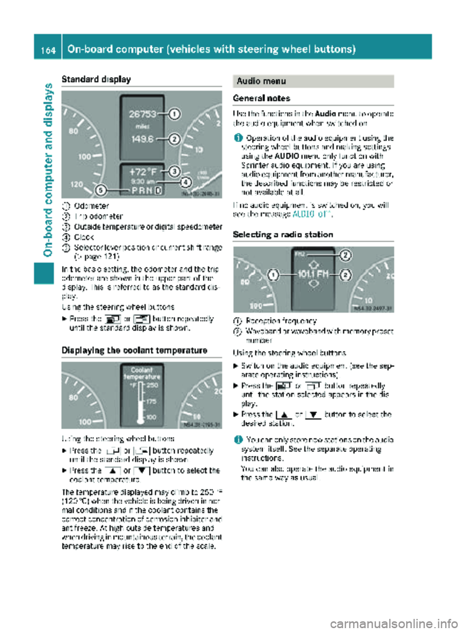
Standard display
:Odometer
;Trip odometer
=Outside temperature or digital speedometer
?Clock
ASelector lever position or current shift range
(Ypage 121)
In the basic setting, the odometer and the trip
odometer are shown in the upper part of the
display. This is referred to as the standard dis-
play.
Using the steering wheel buttons
XPress the VorU button repeatedly
until the standard display is shown.
Displaying the coolant temperature
Using the steering wheel buttons
XPress the VorU button repeatedly
until the standard display is shown.
XPress the 9or: button to select the
coolant temperature.
The temperature displayed may climb to 250 ‡
(120 †) when the vehicle is being driven in nor-
mal conditions and if the coolant contains the
correct concentration of corrosion inhibitor and
antifreeze. At high outside temperatures and
when driving in mountainous terrain, the coolant
temperature may rise to the end of the scale.
Audio menu
General notes
Use the functions in the Audiomenu to operate
the audio equipment when switched on.
iOperation of the audio equipment using the
steering wheel buttons and making settings
using the AUDIOmenu only function with
Sprinter audio equipment. If you are using
audio equipment from another manufacturer,
the described functions may be restricted or
not available at all.
If no audio equipment is switched on, you will
see the message AUDIO off
.
Selecting a radio station
:Reception frequency
;Waveband or waveband with memory preset
number
Using the steering wheel buttons
XSwitch on the audio equipment (see the sep-
arate operating instructions).
XPress the VorU button repeatedly
until the station selected appears in the dis-
play.
XPress the 9or: button to select the
desired station.
iYou can only store new stations on the audio
system itself. See the separate operating
instructions.
You can also operate the audio equipment in
the same way as usual.
164On-board computer (vehicles with steering wheel buttons)
On-board computer and displays
Page 167 of 286
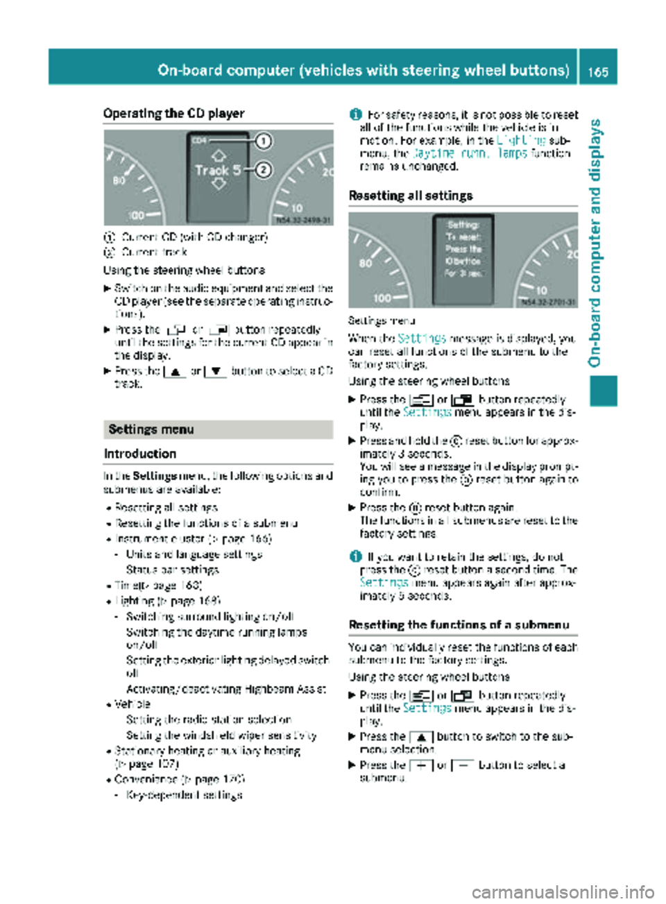
Operating the CD player
:Current CD (with CD changer)
;Current track
Using the steering wheel buttons
XSwitch on the audio equipment and select the
CD player (see the separate operating instruc-
tions).
XPress the VorU button repeatedly
until the settings for the current CD appear in
the display.
XPress the 9or: button to select a CD
track.
Settings menu
Introduction
In the Settings menu, the following options and
submenus are available:
RResetting all settings
RResetting the functions of a submenu
RInstrument cluster (Ypage 166)
-Units and language settings
-Status bar settings
RTime(Ypage 168)
RLighting (Ypage 168)
-Switching surround lighting on/off
-Switching the daytime running lamps
on/off
-Setting the exterior lighting delayed switch-
off
-Activating/deactivating Highbeam Assist
RVehicle
-Setting the radio station selection
-Setting the windshield wiper sensitivity
RStationary heating or auxiliary heating
(Ypage 107)
RConvenience (Ypage 170)
-Key-dependent settings
iFor safety reasons, it is not possible to reset
all of the functions while the vehicle is in
motion. For example, in the Lighting
sub-
menu, the Daytime runn. lampsfunction
remains unchanged.
Resetting all settings
Settings menu
When the Settingsmessage is displayed, you
can reset all functions of the submenu to the
factory settings.
Using the steering wheel buttons
XPress the VorU button repeatedly
until the Settingsmenu appears in the dis-
play.
XPress and hold the 9reset button for approx-
imately 3 seconds.
You will see a message in the display prompt-
ing you to press the 9reset button again to
confirm.
XPress the 9reset button again.
The functions in all submenus are reset to the
factory settings.
iIf you want to retain the settings, do not
press the 9reset button a second time. The
Settings
menu appears again after approx-
imately 5 seconds.
Resetting the functions of a submenu
You can individually reset the functions of each
submenu to the factory settings.
Using the steering wheel buttons
XPress the VorU button repeatedly
until the Settingsmenu appears in the dis-
play.
XPress the 9button to switch to the sub-
menu selection.
XPress the WorX button to select a
submenu.
On-board computer (vehicles with steering wheel buttons)165
On-board computer and displays
Z