turn signal MERCEDES-BENZ V-CLASS MPV 2021 Owners Manual
[x] Cancel search | Manufacturer: MERCEDES-BENZ, Model Year: 2021, Model line: V-CLASS MPV, Model: MERCEDES-BENZ V-CLASS MPV 2021Pages: 337, PDF Size: 9.88 MB
Page 10 of 337
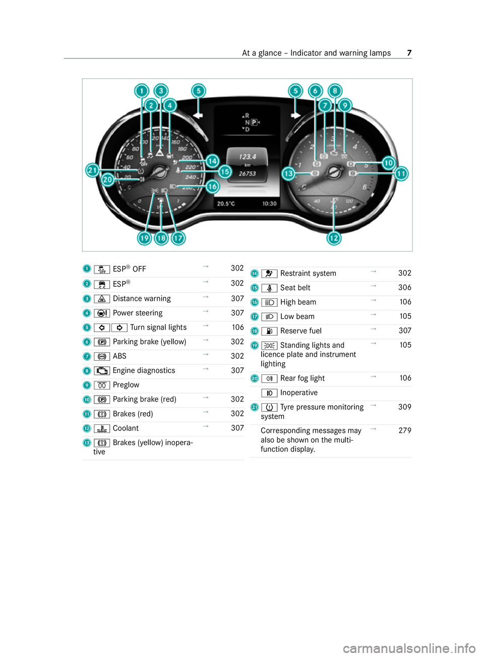
1
00BB ESP®
OFF →
302
2 00E5 ESP®
→
302
3 00BA Distance warning →
307
4 00CC Powe rst eering →
307
5 003E003D Turn signal lights →
106
6 0024 Parking brake (yellow) →
302
7 0025 ABS →
302
8 00B9 Engine diagnostics →
307
9 0028 Preglow
A 0024 Parking brake (red) →
302
B 004D Brakes (red) →
302
C 00AC Coolant →
307
D 004D Brakes (yellow) inopera‐
tive E
0075 Restra int sy stem →
302
F 00E9 Seat belt →
306
G 0057 High beam →
106
H 0058 Low beam →
105
I 00B4 Reser vefuel →
307
J 0060 Standing lights and
licence plate and instrument
lighting →
105
K 005E Rear fog light →
106
005A Inoperative
L 0077 Tyre pressure monitoring
sy stem →
309
Cor responding messages may
also be shown on the multi‐
function displa y. →
279 At
aglance – Indicator and warning lamps 7
Page 52 of 337
Key
Overview of
key functions &
WARNING Risk of accident and inju ry
due toleaving children unat tended in the
ve hicle
If ch ildren are left unat tended in theve hicle,
th ey could, in part icular:
R open doors, thereby endangering other
persons or road users.
R get out and be stru ck byoncoming traf fic.
R operate vehicle equipment and become
trapped, forex ample.
In addition, thech ildren could also set the
ve hicle in motion by,fo rex ample:
R releasing the parking brake.
R changing the transmission position.
R starting theve hicle. #
Never lea vechildren unat tended in the
ve hicle. #
When leaving theve hicle, alw aysta ke
th eke y with you and lock theve hicle. #
Keep theve hicle key out of there ach of
ch ildren. &
WARNING Risk of accident due toinad‐
ve rtent turning of theke y in the ignition
lock
If yo u attach lar geor heavy objects totheke y,
th eke y could inadver tently turn in the ignition
lock while theve hicle is in motion. #
Do not attach any lar geor heavy objects
to thekey. #
Remo veake yring if it is cumbe rsome
before you insert theke y in the ignition
loc k. *
NO
TEDama getotheke y caused bymag‐
netic fields #
Keep theke yaw ay from strong mag‐
netic fields. Ke
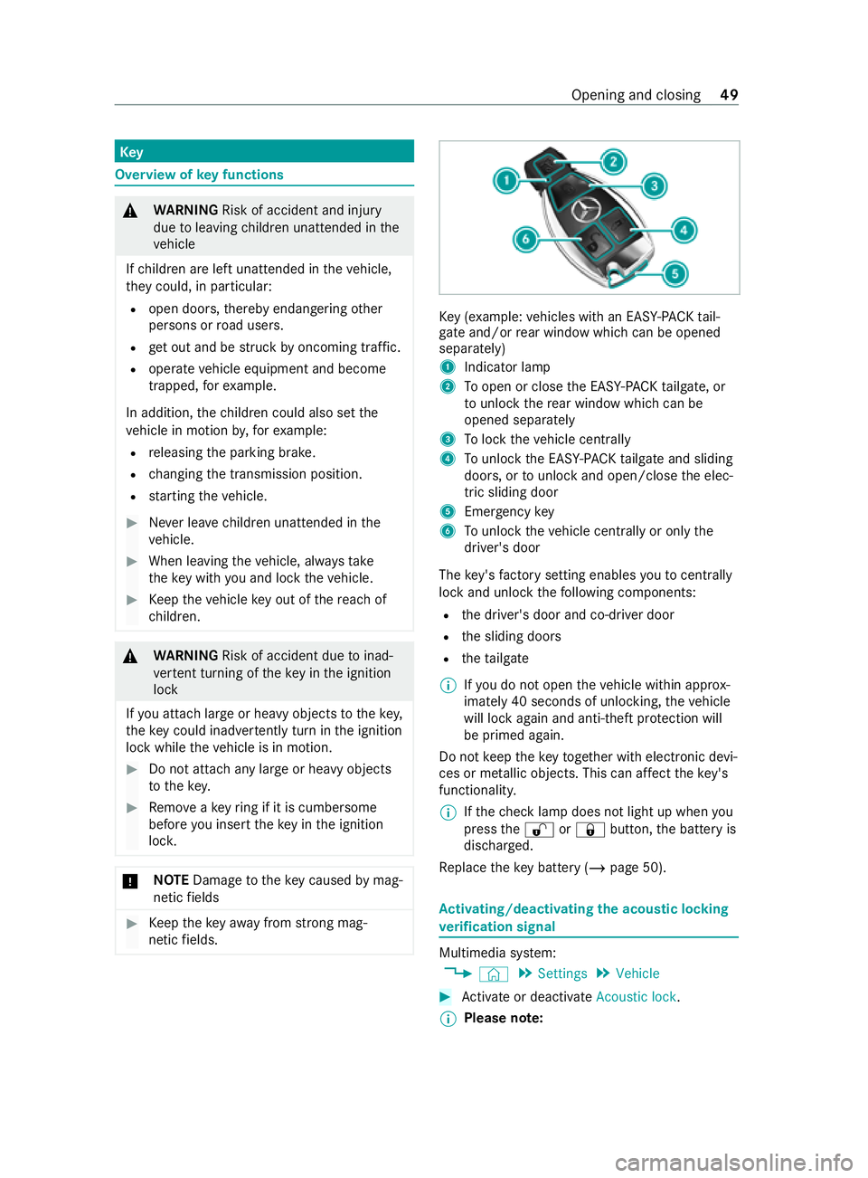
y (e xamp le:vehicles with an EAS Y-PA CK tail‐
ga te and/or rear wind owwhich can be opened
separately)
1 Indicator lamp
2 Toopen or close the EASY -PAC Ktailgate, or
to unlo ck th ere ar wind owwhich can be
opened separately
3 Tolock theve hicle centra lly
4 Tounlo ckthe EASY -PAC Ktailgate and sliding
doors, or tounlo ckand open/close the elec‐
tric sliding door
5 Emer gency key
6 Tounlo cktheve hicle centra lly or onlythe
driver's door
The key's factory setting enables youto centrally
lock and unlock thefo llowing components:
R the driver's door and co-driver door
R the sliding doors
R theta ilgate
% If
yo u do not open theve hicle within appr ox‐
imately 40 seconds of unlocking, theve hicle
will lock again and anti-theft pr otection will
be primed again.
Do not keep theke yto ge ther with electronic devi‐
ces or me tallic objects. This can af fect theke y's
functionalit y.
% If
th ech eck lamp does not light up when you
press the0036 or0037 button, the battery is
dischar ged.
Re place theke y bat tery ( / page 50). Ac
tivating/deactivating the acoustic lo cking
ve rification signal Multimedia sy
stem:
4 © 5
Settings 5
Vehicle #
Activate or deacti vate Acoustic lock .
% Please no
te: Opening and closing
49
Page 64 of 337

Prog
ramming the key button for the tail gate
or rear window
Re quirements
R The tailgate and there ar wind oware closed.
R The ignition is swit ched on.
If yo ur vehicle is fitted wi than EA SY-PAC Ktail‐
gate ,yo u can prog ram the008C button on the
ke y either toopen/close theta ilgate or toopen
th ere ar wind ow. #
Press the buttons in the handle of theta ilgate
and in the handle of there ar wind owsimulta‐
neously for appro ximately five seconds.
Af ter successfully changing the function, the
ve hicle turn signal lamps flash once. #
Check the function of the008C button on the
key. Side window
Opening and closing
the side windo ws &
WARNING Risk of becoming trapped
when opening a side window
When you open a side wind ow, parts of the
body could be dr awn in or become trapped
between the side window and window frame. #
When opening, make sure that nobody
is touching the side windo w. #
If someone is trapped, release the but‐
to n immedia tely or pull it in order to
close the side window again. &
WARNING Risk of becoming trapped
when closing a side window
When closing a side windo w,body parts could
be trapped in the closing area in the process. #
When closing, make sure that no body
parts are in the closing area. #
If someone is trapped, release the but‐
to n immedia tely or press the button in
order toreopen the side windo w. &
WARNING Risk of becoming trapped
when children opera tethe side windo ws
Children could become trapped if they oper‐
ate the side windo ws, particularly when unat‐
te nded. #
Activate thech ild saf ety lock forthe
re ar side wind ows. #
When leaving theve hicle, alw aysta ke
th eke y with you and lock theve hicle. #
Never lea vechildren unat tended in the
ve hicle. &
WARNING Dangertolife due toexposure
to extreme heat or cold in theve hicle
If people, particular lych ildren, are exposed to
ex treme temp eratures over an extended
pe riod of time, there is a risk of serious injury
or danger tolife. #
Never lea vepersons, children in particu‐
lar, unat tended in theve hicle. #
Toopen manuall y:press and hold button 1
or 2. #
Toclose manuall y:pull and hold button 1
or 2.
The windo wsinthe front doors can also be oper‐
ated automaticall y. #
Toopen comple tely: briefly press button 1
or 2 beyond the point of resis tance.
Au tomatic operation will start. #
Toclose comple tely: briefly pull button 1
or 2 beyond the point of resis tance.
Au tomatic operation will start. #
Tointer rupt automatic operation: briefly
press or pull button 1or2 again.
Yo u can still operate the side windo wswhen the
ve hicle is par ked. This function will remain availa‐
ble for around five minutes or until you open a
front door. Opening and closing
61
Page 77 of 337

#
Adjust the seat tothe desired position. #
Adjust theex terior mir rorto the desired posi‐
tion. #
Brief lypress memory button Vandthen
press preset position button 0037,Tor
U within thre e seconds.
An acoustic signal sounds. The settings are
st ored. #
Tocall up: press and hold preset position
button 0037,TorU untilthe seat and
th eex terior mir rors are in thestored position. Ro
tating the front seats &
WARNING Risk of injury orfatal injuries
due tothe driver's seat and front
passenger seat not being engaged
In this situation, there stra int sy stems cann ot
per form their intended pr otective function. #
Enga gethe driver's seat‑ and front
passenger seat in the direction of tra vel
before starting the engine. *
NO
TEDama getothe seats due tocolli‐
sion wi thadjacent car parts The seats can collide with adjacent car parts
when
they are rotated.
This can damage the seats. #
When rotating the seats, make sure
th ere is suf ficient clea rance. Yo
u can rotate the driver's and front passenger
seats by50° and 180°. The seats engage bo thin
and opposite tothe direction of tra vel as well as
at 50° totheex it. #
When rotating the seat, open there spective
front door in order toavoid a collision with
th e door trim. #
Adjust thesteering wheel in such a wayth at
th ere is suf ficient clea rance torotate and
adjust the driver's seat (/ page 96). #
Push le ver1 inthe direction of the ar row.
The turning device will be unloc ked. #
Rotate the seat in the desired direction. #
Ifth ere is a risk of collision with the cent re
console or the B‑pillar, pull le ver2 upwards
and mo vethe front seat forw ards or back‐
wa rds into the desired position. Then release
le ve r2. #
Inthe desired position, make sure that the
seat has engaged in the direction of rotation
and the longitudinal direction. Ad
justing armrests #
Foldthe armrest upwards more than 45° in
position 0048.
The armrest will be unlo cked. #
Foldthe armrest forw ards 0049asfar as it will
go. #
Slowly fold the armrest upwards into the
re qu ired position. #
Tofold the armrest up wards: if necessar y,
fo ld the armrest upwards more than 90° in
position 0047. Re
ar seats and rear ben chseat Note
s onthere ar seats
Yo ur vehicle may be equipped with thefo llowing
seats and bench seats in there ar compartment:
R Standard rear seat
R Luxury rear seat
R Comfort rear ben chseat
R Seat/bunk combination 74
Seats and stowage
Page 109 of 337

&
WARNING Risk of accident when the
dipped beam is switched off in poor visi‐
bility
When the light switch is set to0058 ,the
dipped beam may not be switched on auto‐
matically if there is fog, snow or other causes
of poor visibility such as spr ay.#
In such cases, turn the light switch to
0058 . The automatic driving lights are only an aid.
Re
sponsibility forve hicle lighting rests with you.
If th est anding lights and low beam ha vebeen
switched on, the green 0060(sta nding lights) and
0058 (low beam) indicator lamps on the instru‐
ment clus ter will light up.
Ac tivating/deactivating the fog light
Re quirements:
R The light switch is in the0058 or0058 posi‐
tion.
R The po wer supply has been switched on. #
Toswitch there ar fog light on or off: press
th e button 005E.
Comply with the count ry-specific regulations for
using there ar fog lamp.
Ad justing headlamp range #
Turn headlamp range adjus ter1 tothe
re qu ired position. #
Ifth eve hicle is unladen, select position 005A.
The illumination of thero ad should be 40 m to
10 0 m and low beam must not dazzle oncoming
traf fic. Yo
u can use the headlamp range adjus terto
adjust the light cone of the headlamps to your
ve hicle's load condition. The light cone will
ch ange as the seats are occupied or the load
compartment is loaded or unloaded. This can
cause visibility conditions todeteriorate and you
could dazzle oncoming traf fic. Operating the combination light switch
1
High beam
2 Right turn signal light
3 Headla mpflashing
4 Left turn signal light #
Use the combination switch toactivate the
desired function.
Switching on high beam #
Switch on the low beam (/ page105). #
Push the combination switch forw ards 1.
The 0057 indicator lamp on the instrument
clus ter will light up.
% The high beam switches tothe0058 position
only in darkness and when the engine is run‐
ning. #
Toswitch off: movethe combination switch
back toits starting position.
The 0057 indicator lamp on the instrument
clus ter will light up.
Headlamp flashing #
Brief lypull the combination switch in the
direction of ar row3.
Tu rn signal lights #
Toindicate: pushthe combination switch in
th ere qu ired direction 2or4 until it 106
Light and vision
Page 110 of 337

engages. In
the case of larger steering mo ve‐
ments, the combination switch will automati‐
cally switch bac k. #
Toindicate briefl y:tapth e combination
switch briefly in there qu ired direction 2or
4. The cor responding turn signal lamp will
fl ash thre e times. Switching
the hazard warning light sy stem
on/off #
Press button 1.
If yo u operate a turn signal indicator while the
hazard warning light sy stem is switched on, only
th e turn signal lamps on there leva nt side of the
ve hicle will light up.
The hazard warning light sy stem will switch on
automatically in thefo llowing situations:
R The airbag is deplo yed
R The vehicle is heavily braked from a speed of
more than 70 km/h toast andstill.
The hazard warning light sy stem will automati‐
cally switch off when theve hicle rega ins a speed
of more than 10 km/h af ter maximum full-s top
braking.
% The hazard
warning light sy stem will work
eve n when theve hicle has been switched off. Intelligent Light Sy
stem Fu
nction of the Intelligent Light Sy stem
The In telligent Light Sy stem adapts the head‐
lamps' lighting function tothe cur rent driving and
we ather situation. The sy
stem comprises thefo llowing functions:
R Active light function (/ page 107)
R Cornering light (/ page107)
R Motorw ay mode (/ page108)
R Enhanced fog light function (/ page108)
Yo u can swit ch the Intelligent Light Sy stem func‐
tion on or off via the on-board computer
(/ page 108).
Ac tive light function The acti
velight function has thefo llowing func‐
tions:
R The headlamps follow thesteering mo ve‐
ments.
R Releva nt areas are better illumina ted during a
journe y.
The functions will be active when low beam is
switched on.
The active light function can, forex ample, de tect
pedestrians, cyclist s and animals at an earlier
st age.
Cornering light function The function is active under
thefo llowing condi‐
tions:
R Your speed is less than 40 km/h and the turn
signal light has been switched on or the
st eering wheel is turned.
R Your speed is between 40 km/h and
70 km/h and thesteering wheel is turned. Light and vision
107
Page 115 of 337

sar
y,clean theglass tube with alcohol or spi‐
ri ts while it is cold and wipe it down wi th a
lint-f ree clo th.
R Protect light sources from moisture and do
not bring them into contact with liquids.
Alw ays ensure the bulbs are firm ly secu red.
Ha ve thefo llowing light sources changed at a
qu alified specialist workshop only:
R Additional turn signal lamps on the outside
mir ror
R Bulbs in the licence plate lighting Re
placing front light bulbs (vehicles with hal‐
ogen headlamps) Overview of front light sourc
e types1
Additional turn signal lamp on the outside
mir ror: LED
2 Turn signal light: PY 21 W
3 Low beam: H7 55 W
4 High beam/s tanding/parking lights/daytime
ru nning lights: H15 55 W/15 W
Re placing light sou rces in the headlamp
Re quirements
R The lighting sy stem is switched off.
R The appropriate front wheel is turned
inwa rds.
R Low beam: youre qu ire a H7 55 W light bulb.
R Turn signal light: yourequ ire a PY 21W light
bulb.
R High beam /
standing/parking lights /
daytime running lights: youre qu ire a
H15 55 W/15 W light bulb. Fi
tting/ removing the co ver in the front wheel
ar ch #
Toremo ve:grip the cent reof co ver1, slide
it upwards and pull it out.
The co ver will hang down wards on thest ra p. #
Tofit: insert co ver1 attheto p and slide it
down wards until it engages.
Low beam #
Remo vethe co ver in the front wheel ar ch. #
Turn housing co ver1 anti-clockwise and
re mo veit. #
Turn soc ket2 for low beam tothe left and
pull it out. #
Pull the bulb out of soc ket2. #
Inse rtthe new bulb into soc ket2. #
Inse rtsoc ket2 and rotate itto theright to
tighten it. #
Press on housing co ver1 and rotate itto
th eright totighten it. 11 2
Light and vision
Page 116 of 337
#
Replace the co ver in the front wheel ar ch.
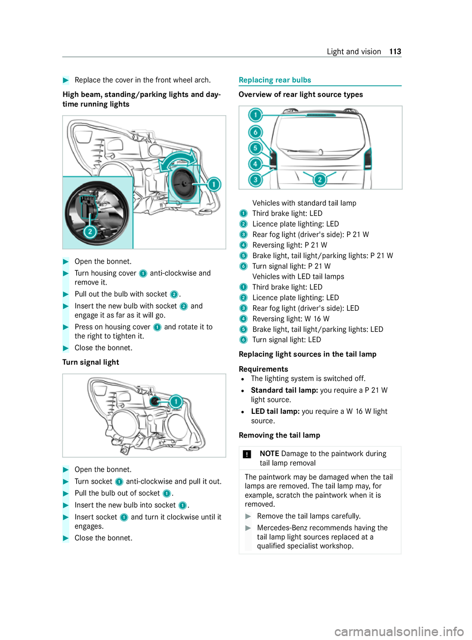
High beam, standing/parking lights and day‐
time running lights #
Open the bonn et. #
Turn housing co ver1 anti-clockwise and
re mo veit. #
Pull out the bulb with soc ket2. #
Inse rtthe new bulb with soc ket2 and
engage it as far as it will go. #
Press on housing co ver1 and rotate itto
th eright totighten it. #
Close the bonn et.
Tu rn signal light #
Open the bonn et. #
Turn soc ket1 anti-clo ckwise and pull it out. #
Pull the bulb out of soc ket1. #
Inse rtthe new bulb into soc ket1. #
Inse rtsoc ket1 and turn it clo ckwise until it
engages. #
Close the bonn et. Re
placing rear bulbs Overview of
rear light source types Ve
hicles with standard tail lamp
1 Third brake light: LED
2 Licence plate lighting: LED
3 Rear fog light (driver's side): P 21 W
4 Reversing light: P 21 W
5 Brake light, tail light/parking lights: P 21 W
6 Turn signal light: P 21 W
Ve hicles with LED tail lamps
1 Third brake light: LED
2 Licence plate lighting: LED
3 Rear fog light (driver's side): LED
4 Reversing light: W 16 W
5 Brake light, tail light/parking lights: LED
6 Turn signal light: LED
Re placing light sou rces in the tail lamp
Re quirements
R The lighting sy stem is switched off.
R Standard tail lamp: yourequ ire a P 21 W
light source.
R LED tail lamp: yourequ ire a W 16W light
source.
Re moving the tail lamp
* NO
TEDama getothe paintwork during
ta il lamp remo val The paintwork may be damaged when
theta il
lamps are remo ved. The tail lamp ma y,for
ex ample, scratch the paintwork when it is
re mo ved. #
Remo vetheta il lamps carefull y. #
Mercedes-Benz recommends having the
ta il lamp light sources replaced at a
qu alified specialist workshop. Light and vision
11 3
Page 117 of 337
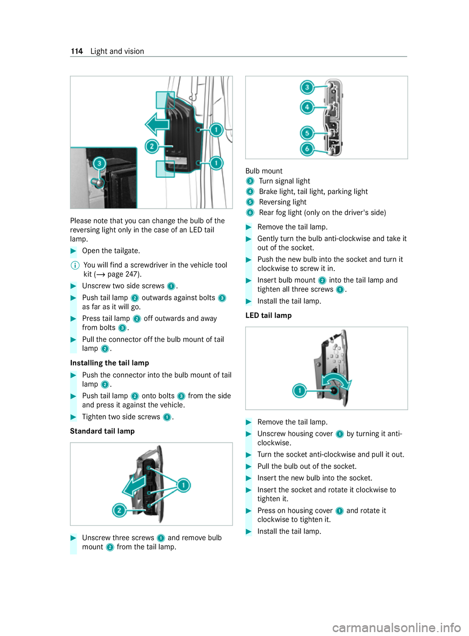
Please no
tethat you can change the bulb of the
re ve rsing light only in the case of an LED tail
lamp. #
Open theta ilgate.
% Yo
u will find a scr ewdriver in theve hicle tool
kit (/ page247). #
Unscr ewtwo side scre ws1. #
Push tail lamp 2outwards against bolts 3
as far as it will go. #
Press tail lamp 2off outwards and away
from bolts 3. #
Pull the connector off the bulb mount of tail
lamp 2.
Installing the tail lamp #
Push the connector into the bulb mount of tail
lamp 2. #
Push tail lamp 2onto bolts 3from the side
and press it against theve hicle. #
Tighten two side scr ews1.
St andard tail lamp #
Unscr ewthre e scr ews1 and remo vebulb
mount 2from theta il lamp. Bulb mount
3
Turn signal light
4 Brake light, tail light, parking light
5 Reversing light
6 Rear fog light (only on the driver's side) #
Remo vetheta il lamp. #
Gently turn the bulb anti-clockwise and take it
out of the soc ket. #
Push the new bulb into the soc ket and turn it
clo ckwise toscr ew it in. #
Insert bulb mount 2into theta il lamp and
tigh ten all thre e scr ews1. #
Installth eta il lamp.
LED tail lamp #
Remo vetheta il lamp. #
Unscr ewhousing co ver1 byturning it anti-
clo ckwise. #
Turn the soc ket anti-clo ckwise and pull it out. #
Pull the bulb out of the soc ket. #
Inse rtthe new bulb into the soc ket. #
Inse rtthe soc ket and rotate it clockwise to
tighten it. #
Press on housing co ver1 and rotate it
clockwise totighten it. #
Installth eta il lamp. 11 4
Light and vision
Page 118 of 337
Re
placing interior light bulbs Re
placing light sou rces in the interior
Re quirements
R The interior lighting has been switched off.
R Rear and load comp artment lamp:you
requ ire a T10 6W xenon light sou rce.
R Interior and sur round lighting: yourequ ire
a W 5 W light source.
R Signal and ambient lamp in
the tailgate:
yo ure qu ire a W 5 W light source.
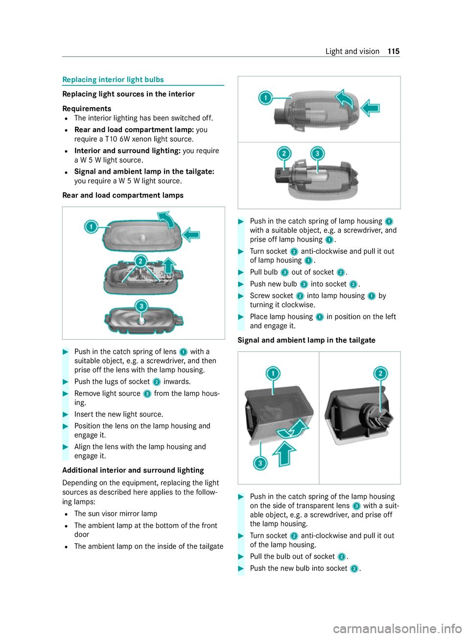
Re ar and load comp artment lamps #
Push in the catch spring of lens 1with a
suitable object, e.g. a scr ewdriver, and then
prise off the lens with the lamp housing. #
Push the lugs of soc ket2 inwa rds. #
Remo velight source 3from the lamp hous‐
ing. #
Insert the new light source. #
Position the lens on the lamp housing and
engage it. #
Align the lens with the lamp housing and
engage it.
Ad ditional interior and sur round lighting
Depending on the equipment, replacing the light
sources as described here applies tothefo llow‐
ing lamps:
R The sun visor mir ror lamp
R The ambient lamp at the bottom of the front
door
R The ambient lamp on the inside of theta ilgate #
Push in the catch spring of lamp housing 1
with a suitable object, e.g. a scr ewdriver, and
prise off lamp housing 1. #
Turn soc ket2 anti-clo ckwise and pull it out
of lamp housing 1. #
Pull bulb 3out of soc ket2. #
Push new bulb 3into soc ket2. #
Screw soc ket2 into la mphousing 1by
turning it clo ckwise. #
Place lamp housing 1in position on the left
and engage it.
Signal and ambient lamp in the tailgate #
Push in the catch spring of the lamp housing
on the side of transparent lens 3with a suit‐
able object, e.g. a scr ewdriver, and prise off
th e lamp housing. #
Turn soc ket2 anti-clo ckwise and pull it out
of the lamp housing. #
Pull the bulb out of soc ket2. #
Push the new bulb into soc ket2. Light and vision
11 5