ABS Mercury Grand Marquis 2001 Owner's Manuals
[x] Cancel search | Manufacturer: MERCURY, Model Year: 2001, Model line: Grand Marquis, Model: Mercury Grand Marquis 2001Pages: 240, PDF Size: 1.86 MB
Page 12 of 240
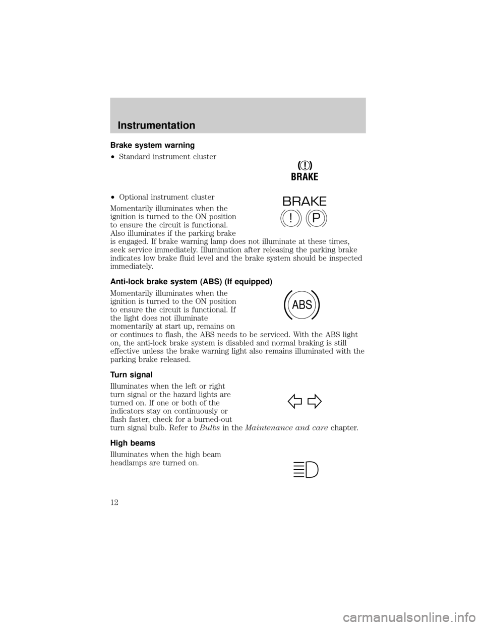
Brake system warning
²Standard instrument cluster
²Optional instrument cluster
Momentarily illuminates when the
ignition is turned to the ON position
to ensure the circuit is functional.
Also illuminates if the parking brake
is engaged. If brake warning lamp does not illuminate at these times,
seek service immediately. Illumination after releasing the parking brake
indicates low brake fluid level and the brake system should be inspected
immediately.
Anti-lock brake system (ABS) (If equipped)
Momentarily illuminates when the
ignition is turned to the ON position
to ensure the circuit is functional. If
the light does not illuminate
momentarily at start up, remains on
or continues to flash, the ABS needs to be serviced. With the ABS light
on, the anti-lock brake system is disabled and normal braking is still
effective unless the brake warning light also remains illuminated with the
parking brake released.
Turn signal
Illuminates when the left or right
turn signal or the hazard lights are
turned on. If one or both of the
indicators stay on continuously or
flash faster, check for a burned-out
turn signal bulb. Refer toBulbsin theMaintenance and carechapter.
High beams
Illuminates when the high beam
headlamps are turned on.
!
BRAKE
P!
BRAKE
ABS
Instrumentation
12
Page 134 of 240
BRAKES
Your service brakes are self-adjusting. Refer to the scheduled
maintenance guide for scheduled maintenance.
Occasional brake noise is normal and often does not indicate a
performance concern with the vehicle's brake system. In normal
operation, automotive brake systems may emit occasional or intermittent
squeal or groan noises when the brakes are applied. Such noises are
usually heard during the first few brake applications in the morning;
however, they may be heard at any time while braking and can be
aggravated by environmental conditions such as cold, heat, moisture,
road dust, salt or mud. If a ªmetal-to-metal,º ªcontinuous grindingº or
ªcontinuous squealº sound is present while braking, the brake linings
may be worn-out and should be inspected by a qualified service
technician.
Anti-lock brake system (ABS) (if equipped)
On vehicles equipped with an anti-lock braking system (ABS), a noise
from the hydraulic pump motor and pulsation in the pedal may be
observed during ABS braking events. Pedal pulsation coupled with noise
while braking under panic conditions or on loose gravel, bumps, wet or
snowy roads is normal and indicates proper functioning of the vehicle's
anti-lock brake system. The ABS performs a self-check after you start
the engine and begin to drive away. A brief mechanical noise may be
heard during this test. This is normal. If a malfunction is found, the ABS
warning light will come on. If the vehicle has continuous vibration or
shudder in the steering wheel while braking, the vehicle should be
inspected by a qualified service technician.
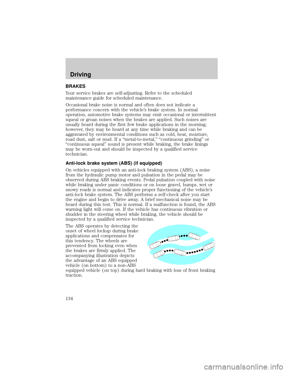
The ABS operates by detecting the
onset of wheel lockup during brake
applications and compensates for
this tendency. The wheels are
prevented from locking even when
the brakes are firmly applied. The
accompanying illustration depicts
the advantage of an ABS equipped
vehicle (on bottom) to a non-ABS
equipped vehicle (on top) during hard braking with loss of front braking
traction.
Driving
134
Page 135 of 240
ABS warning lampABS
TheABSwarning lamp in the instrument cluster momentarily illuminates
when the ignition is turned to the ON position. If the light does not
illuminate momentarily at start up, remains on or continues to flash, the
ABS needs to be serviced.
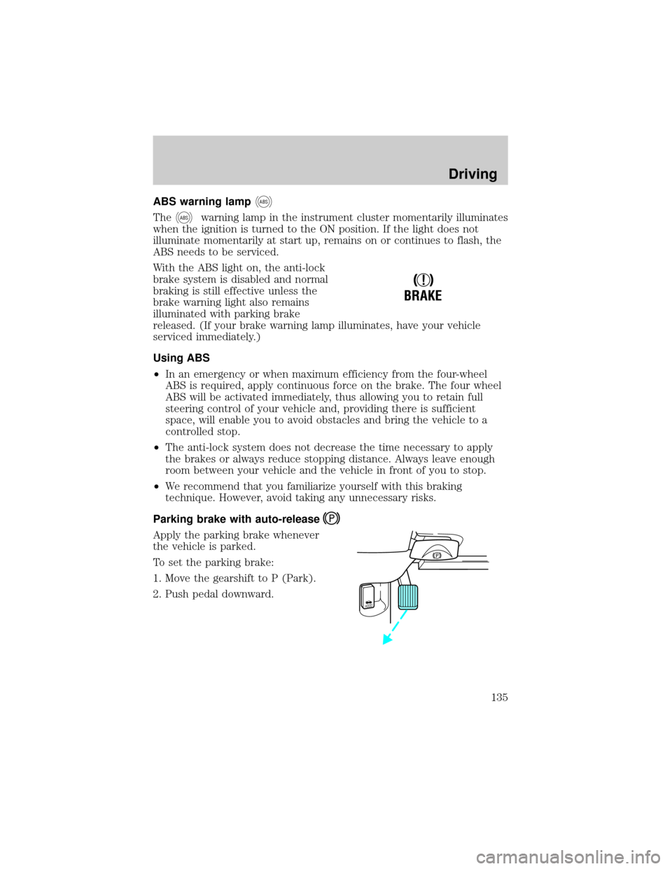
With the ABS light on, the anti-lock
brake system is disabled and normal
braking is still effective unless the
brake warning light also remains
illuminated with parking brake
released. (If your brake warning lamp illuminates, have your vehicle
serviced immediately.)
Using ABS
²In an emergency or when maximum efficiency from the four-wheel
ABS is required, apply continuous force on the brake. The four wheel
ABS will be activated immediately, thus allowing you to retain full
steering control of your vehicle and, providing there is sufficient
space, will enable you to avoid obstacles and bring the vehicle to a
controlled stop.
²The anti-lock system does not decrease the time necessary to apply
the brakes or always reduce stopping distance. Always leave enough
room between your vehicle and the vehicle in front of you to stop.
²We recommend that you familiarize yourself with this braking
technique. However, avoid taking any unnecessary risks.
Parking brake with auto-release
Apply the parking brake whenever
the vehicle is parked.
To set the parking brake:
1. Move the gearshift to P (Park).
2. Push pedal downward.
!
BRAKE
HOOD
Driving
135
Page 137 of 240
The system operates by detecting and controlling wheel spin. The system
borrows many of the electronic and mechanical elements already present
in the anti-lock braking system (ABS).
Wheel-speed sensors allow excess rear wheel spin to be detected by the
Traction Controlyportion of the ABS computer. Any excessive wheel
spin is controlled by automatically applying and releasing the rear brakes
in conjunction with engine torque reductions. Engine torque reduction is
realized via the fully electronic spark and fuel injection systems. This
process is very sensitive to driving conditions and very fast acting. The
rear wheels ªsearchº for optimum traction several times a second and
adjustments are made accordingly.
The Traction Controlysystem will allow your vehicle to make better use
of available traction on slippery surfaces. The system is a driver aid
which makes your vehicle easier to handle primarily on snow and ice
covered roads.
During Traction Controlyoperation you may hear an electric motor type
of sound coming from the engine compartment and the engine will not
ªrev-upº when you push further on the accelerator. This is normal
system behavior.
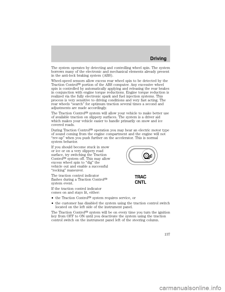
If you should become stuck in snow
or ice or on a very slippery road
surface, try switching the Traction
Controlysystem off. This may allow
excess wheel spin to ªdigº the
vehicle out and enable a successful
ªrockingº maneuver.
The traction control indicator
flashes during a Traction Controly
system event.
If the traction control indicator
comes on and stays lit, either:
²the Traction Controlysystem requires service, or
²the customer has disabled the system using the traction control switch
located on the left side of the instrument panel.
The Traction Controlysystem will be on every time you turn the ignition
key from OFF to ON until you deactivate the system using the traction
control switch on the instrument panel left of the steering column.
TRAC
CNTL
Driving
137
Page 154 of 240
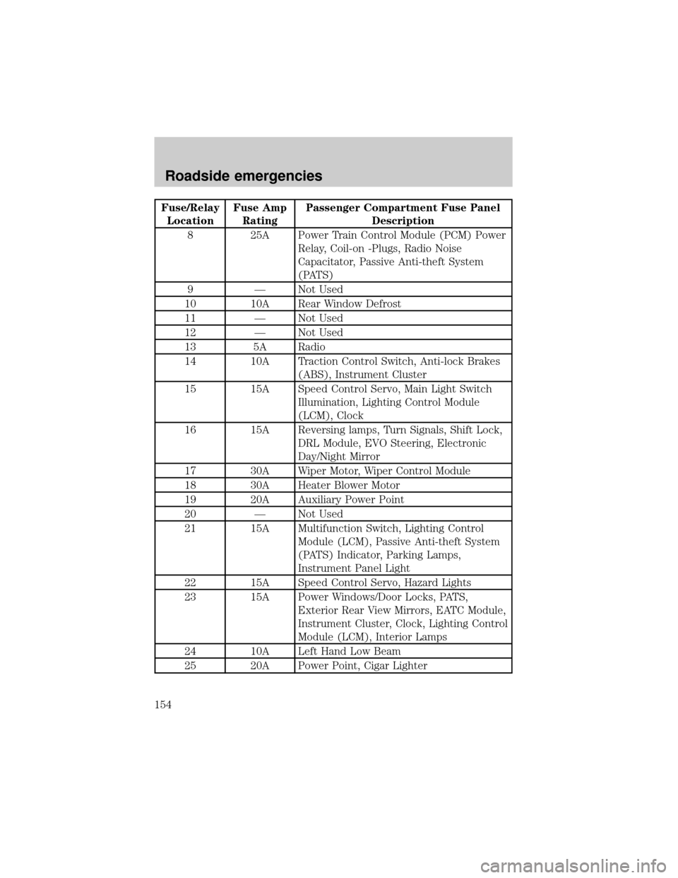
Fuse/Relay
LocationFuse Amp
RatingPassenger Compartment Fuse Panel
Description
8 25A Power Train Control Module (PCM) Power
Relay, Coil-on -Plugs, Radio Noise
Capacitator, Passive Anti-theft System
(PATS)
9 Ð Not Used
10 10A Rear Window Defrost
11 Ð Not Used
12 Ð Not Used
13 5A Radio
14 10A Traction Control Switch, Anti-lock Brakes
(ABS), Instrument Cluster
15 15A Speed Control Servo, Main Light Switch
Illumination, Lighting Control Module
(LCM), Clock
16 15A Reversing lamps, Turn Signals, Shift Lock,
DRL Module, EVO Steering, Electronic
Day/Night Mirror
17 30A Wiper Motor, Wiper Control Module
18 30A Heater Blower Motor
19 20A Auxiliary Power Point
20 Ð Not Used
21 15A Multifunction Switch, Lighting Control
Module (LCM), Passive Anti-theft System
(PATS) Indicator, Parking Lamps,
Instrument Panel Light
22 15A Speed Control Servo, Hazard Lights
23 15A Power Windows/Door Locks, PATS,
Exterior Rear View Mirrors, EATC Module,
Instrument Cluster, Clock, Lighting Control
Module (LCM), Interior Lamps
24 10A Left Hand Low Beam
25 20A Power Point, Cigar Lighter
Roadside emergencies
154
Page 155 of 240
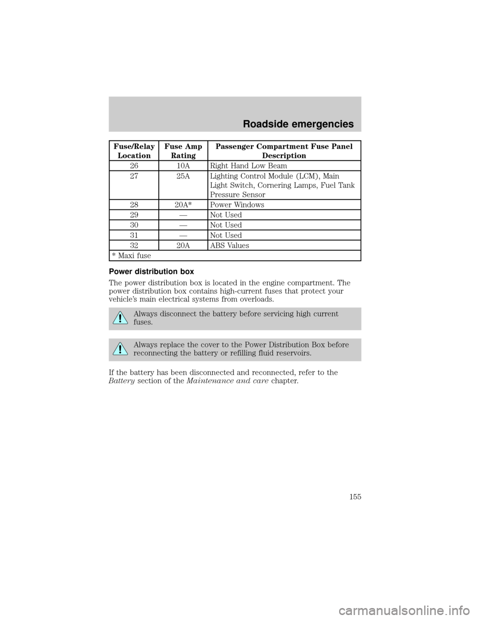
Fuse/Relay
LocationFuse Amp
RatingPassenger Compartment Fuse Panel
Description
26 10A Right Hand Low Beam
27 25A Lighting Control Module (LCM), Main
Light Switch, Cornering Lamps, Fuel Tank
Pressure Sensor
28 20A* Power Windows
29 Ð Not Used
30 Ð Not Used
31 Ð Not Used
32 20A ABS Values
* Maxi fuse
Power distribution box
The power distribution box is located in the engine compartment. The
power distribution box contains high-current fuses that protect your
vehicle's main electrical systems from overloads.
Always disconnect the battery before servicing high current
fuses.
Always replace the cover to the Power Distribution Box before
reconnecting the battery or refilling fluid reservoirs.
If the battery has been disconnected and reconnected, refer to the
Batterysection of theMaintenance and carechapter.
Roadside emergencies
155
Page 196 of 240
Observe the following guidelines when handling automotive fuel:
²Extinguish all smoking materials
and any open flames before
fueling your vehicle.
²Always turn off the vehicle before
fueling.
²Automotive fuels can be harmful
or fatal if swallowed. Fuel such as
gasoline is highly toxic and if
swallowed can cause death or
permanent injury. If fuel is
swallowed, call a physician immediately, even if no symptoms are
immediately apparent. The toxic effects of fuel may not be visible for
hours.
²Avoid inhaling fuel vapors. Inhaling too much fuel vapor of any kind
can lead to eye and respiratory tract irritation. In severe cases,
excessive or prolonged breathing of fuel vapor can cause serious
illness and permanent injury.
²Avoid getting fuel liquid in your eyes. If fuel is splashed in the eyes,
remove contact lenses (if worn), flush with water for 15 minutes and
seek medical attention. Failure to seek proper medical attention could
lead to permanent injury.
²Fuels can also be harmful if absorbed through the skin. If fuel is
splashed on the skin and/or clothing, promptly remove contaminated
clothing and wash skin thoroughly with soap and water. Repeated or
prolonged skin contact with fuel liquid or vapor causes skin irritation.
²Be particularly careful if you are taking ªAntabuseº or other forms of
disulfiram for the treatment of alcoholism. Breathing gasoline vapors,
or skin contact could cause an adverse reaction. In sensitive
individuals, serious personal injury or sickness may result. If fuel is
splashed on the skin, promptly wash skin thoroughly with soap and
water. Consult a physician immediately if you experience an adverse
reaction.
When refueling always shut the engine off and never allow
sparks or open flames near the filler neck. Never smoke while
refueling. Fuel vapor is extremely hazardous under certain conditions.
Care should be taken to avoid inhaling excess fumes.
Maintenance and care
196
Page 197 of 240
The flow of fuel through a fuel pump nozzle can produce static
electricity, which can cause a fire if fuel is pumped into an
ungrounded fuel container.
Use the following guidelines to avoid static build-up when filling an
ungrounded fuel container:
²Place approved fuel container on the ground.
²DO NOT fill a fuel container while it is in the vehicle (including the
cargo area).
²Keep the fuel pump nozzle in contact with the fuel container while
filling.
²DO NOT use a device that would hold the fuel pump handle in the fill
position.
Fuel Filler Cap
Your fuel tank filler cap has an indexed design with a 1/8 turn on/off
feature.
When fueling your vehicle:
1. Turn the engine off.
2. Carefully turn the filler cap counterclockwise 1/8 of a turn until it
stops.
3. Pull to remove the cap from the fuel filler pipe.
4. To install the cap, align the tabs on the cap with the notches on the
filler pipe.
5. Turn the filler cap clockwise 1/8 of a turn until it stops.
ªCheck Fuel Capº illuminates when the ignition is turned to the ON
position to ensure your bulb is working. When this light turns on, check
the fuel filler cap. Continuing to operate the vehicle with the Check Fuel
Cap light on, can activate the Service Engine Soon warning. When the
fuel filler cap is properly re-installed, the light(s) will turn off after a
period of normal driving.It may take a long period of time for the
system to detect an improperly installed fuel filler cap.
If you must replace the fuel filler cap, replace it with a fuel filler
cap that is designed for your vehicle. The customer warranty may
be void for any damage to the fuel tank or fuel system if the
correct genuine Ford or Motorcraft fuel filler cap is not used.
Maintenance and care
197
Page 206 of 240
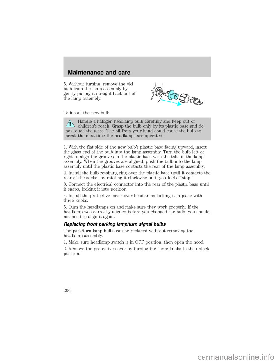
5. Without turning, remove the old
bulb from the lamp assembly by
gently pulling it straight back out of
the lamp assembly.
To install the new bulb:
Handle a halogen headlamp bulb carefully and keep out of
children's reach. Grasp the bulb only by its plastic base and do
not touch the glass. The oil from your hand could cause the bulb to
break the next time the headlamps are operated.
1. With the flat side of the new bulb's plastic base facing upward, insert
the glass end of the bulb into the lamp assembly. Turn the bulb left or
right to align the grooves in the plastic base with the tabs in the lamp
assembly. When the grooves are aligned, push the bulb into the lamp
assembly until the plastic base contacts the rear of the lamp assembly.
2. Install the bulb retaining ring over the plastic base until it contacts the
rear of the socket by rotating it clockwise until you feel a ªstop.º
3. Connect the electrical connector into the rear of the plastic base until
it snaps, locking it into position.
4. Install the protective cover over headlamps locking it in place with
three knobs.
5. Turn the headlamps on and make sure they work properly. If the
headlamp was correctly aligned before you changed the bulb, you should
not need to align it again.
Replacing front parking lamp/turn signal bulbs
The park/turn lamp bulbs can be replaced with out removing the
headlamp assembly.
1. Make sure headlamp switch is in OFF position, then open the hood.
2. Remove the protective cover by turning the three knobs to the unlock
position.
Maintenance and care
206
Page 234 of 240

A
Air bag supplemental restraint
system ........................................116
and child safety seats ............118
description ..............................116
disposal ....................................120
driver air bag ..........................118
indicator light ...................10, 120
operation .................................118
passenger air bag ...................118
Air cleaner filter ...............188, 216
Air conditioning ..........................29
automatic temperature
control system ..........................32
Air suspension ...........................138
description ..............................138
warning light .............................13
Antifreeze (see Engine
coolant) .....................................175
Anti-lock brake system
(see Brakes) ......................134±135
Audio system (see Radio) .........38
Automatic transmission
driving an automatic
overdrive .................................140
fluid, adding ............................183
fluid, checking ........................183
fluid, refill capacities ..............216
fluid, specification ..................219
Auxiliary power point ...........65, 83
Axle
lubricant specifications ..218±219
refill capacities ........................216
traction lok ..............................143B
Battery .......................................186
acid, treating emergencies .....186
charging system warning light..13
jumping a disabled battery ....162
maintenance-free ....................186
replacement, specifications ...216
servicing ..................................186
voltage gauge ............................21
Belt minder ...............................112
Brakes ........................................134
anti-lock ...........................134±135
anti-lock brake system
(ABS) warning light .........12, 135
brake warning light ..................12
fluid, checking and adding ....174
fluid, refill capacities ..............216
fluid, specifications .........218±219
lubricant specifications ..218±219
pedals (see Power adjustable
foot pedals) ...............................64
shift interlock ..........................139
Break-in period .............................3
C
Capacities for refilling fluids ....216
Cassette tape player ...................50
CD changer .................................60
Certification Label ....................221
Child safety restraints ..............121
child safety belts ....................121
Child safety seats ......................122
attaching with tether straps ..127
in front seat ............................124
in rear seat ......................124, 126
Cleaning your vehicle ...............210
Index
234