relay Mercury Grand Marquis 2001 Owner's Manuals
[x] Cancel search | Manufacturer: MERCURY, Model Year: 2001, Model line: Grand Marquis, Model: Mercury Grand Marquis 2001Pages: 240, PDF Size: 1.86 MB
Page 139 of 240
This system keeps the rear of your vehicle at a constant level by
automatically adding air or releasing air from the springs.
If you exceed the load limit, the rear air suspension may not operate.
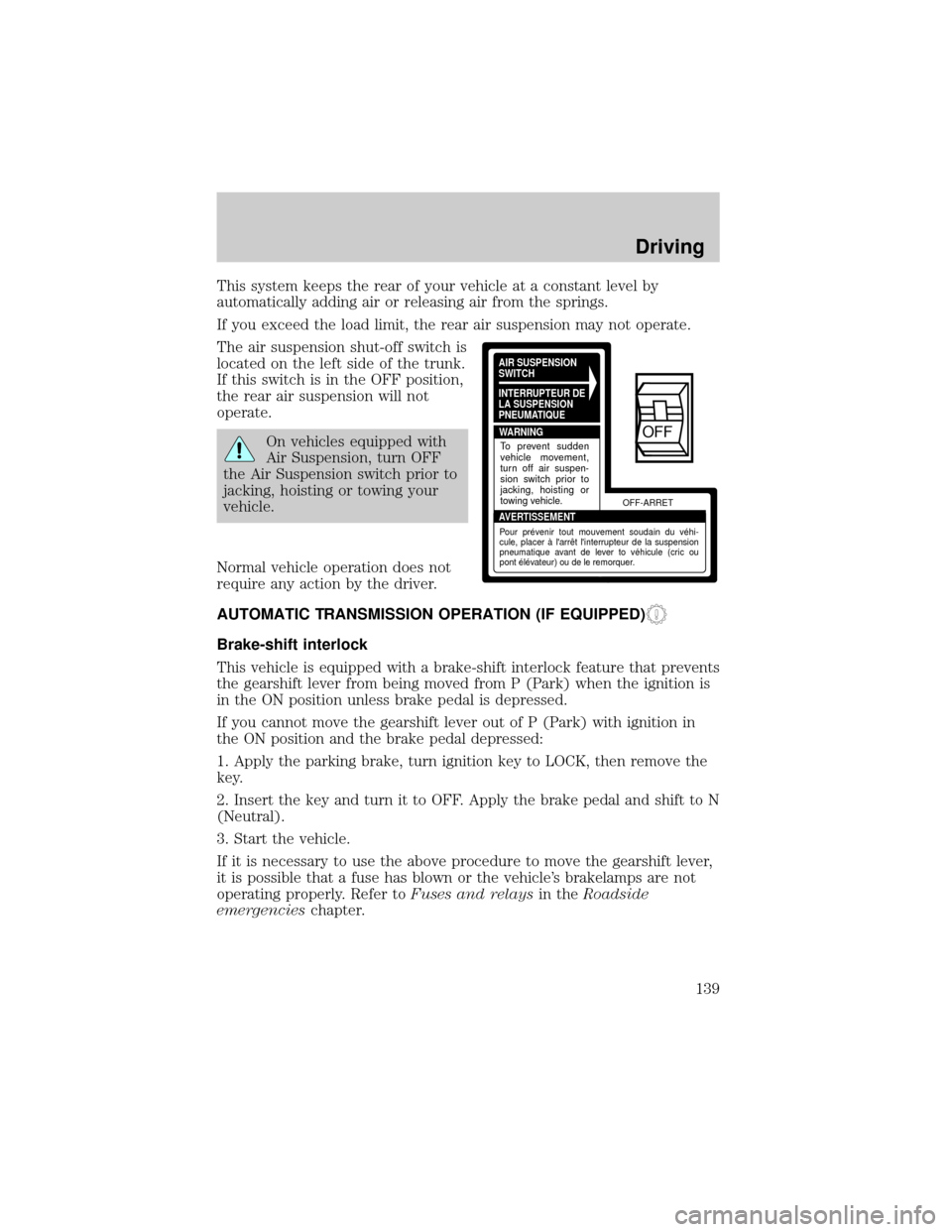
The air suspension shut-off switch is
located on the left side of the trunk.
If this switch is in the OFF position,
the rear air suspension will not
operate.
On vehicles equipped with
Air Suspension, turn OFF
the Air Suspension switch prior to
jacking, hoisting or towing your
vehicle.
Normal vehicle operation does not
require any action by the driver.
AUTOMATIC TRANSMISSION OPERATION (IF EQUIPPED)
Brake-shift interlock
This vehicle is equipped with a brake-shift interlock feature that prevents
the gearshift lever from being moved from P (Park) when the ignition is
in the ON position unless brake pedal is depressed.
If you cannot move the gearshift lever out of P (Park) with ignition in
the ON position and the brake pedal depressed:
1. Apply the parking brake, turn ignition key to LOCK, then remove the
key.
2. Insert the key and turn it to OFF. Apply the brake pedal and shift to N
(Neutral).
3. Start the vehicle.
If it is necessary to use the above procedure to move the gearshift lever,
it is possible that a fuse has blown or the vehicle's brakelamps are not
operating properly. Refer toFuses and relaysin theRoadside
emergencieschapter.
AIR SUSPENSION
SWITCH
INTERRUPTEUR DE
LA SUSPENSION
PNEUMATIQUE
WARNING
AVERTISSEMENTOFF-ARRET
To prevent sudden
vehicle movement,
turn off air suspen-
sion switch prior to
jacking, hoisting or
towing vehicle.
Pour prévenir tout mouvement soudain du véhi-
cule, placer à l'arrêt l'interrupteur de la suspension
pneumatique avant de lever to véhicule (cric ou
pont élévateur) ou de le remorquer.
OFF
Driving
139
Page 152 of 240
FUSES AND RELAYS
Fuses
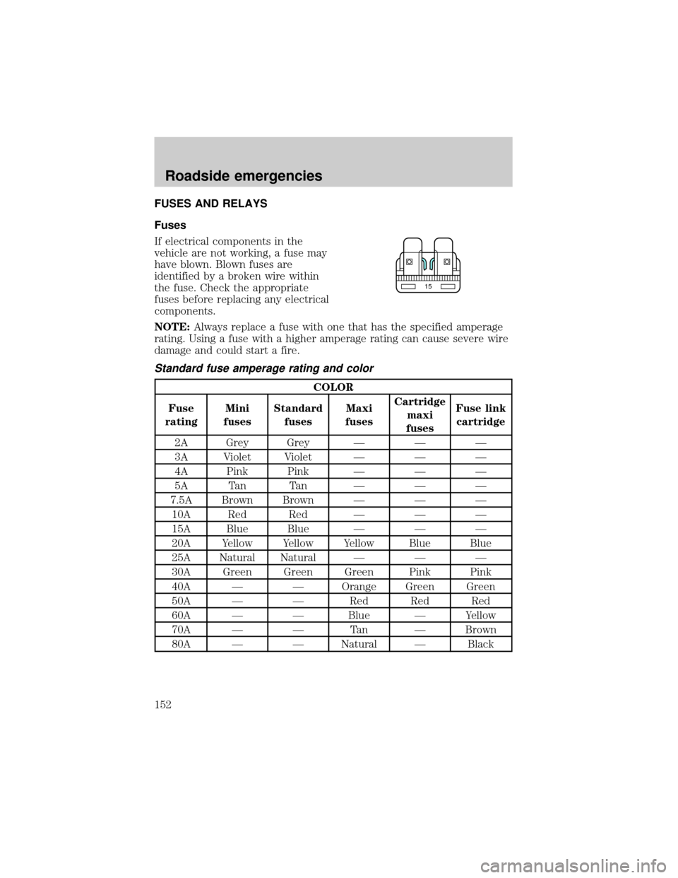
If electrical components in the
vehicle are not working, a fuse may
have blown. Blown fuses are
identified by a broken wire within
the fuse. Check the appropriate
fuses before replacing any electrical
components.
NOTE:Always replace a fuse with one that has the specified amperage
rating. Using a fuse with a higher amperage rating can cause severe wire
damage and could start a fire.
Standard fuse amperage rating and color
COLOR
Fuse
ratingMini
fusesStandard
fusesMaxi
fusesCartridge
maxi
fusesFuse link
cartridge
2A Grey Grey Ð Ð Ð
3A Violet Violet Ð Ð Ð
4A Pink Pink Ð Ð Ð
5A Tan Tan Ð Ð Ð
7.5A Brown Brown Ð Ð Ð
10A Red Red Ð Ð Ð
15A Blue Blue Ð Ð Ð
20A Yellow Yellow Yellow Blue Blue
25A Natural Natural Ð Ð Ð
30A Green Green Green Pink Pink
40A Ð Ð Orange Green Green
50A Ð Ð Red Red Red
60A Ð Ð Blue Ð Yellow
70A Ð Ð Tan Ð Brown
80A Ð Ð Natural Ð Black
15
Roadside emergencies
152
Page 153 of 240
Passenger compartment fuse panel
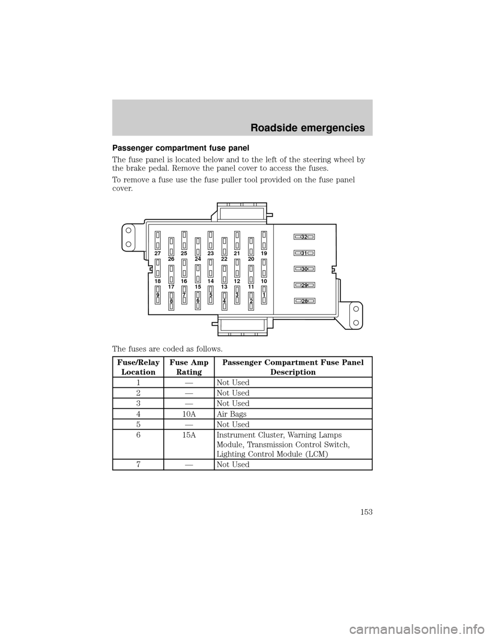
The fuse panel is located below and to the left of the steering wheel by
the brake pedal. Remove the panel cover to access the fuses.
To remove a fuse use the fuse puller tool provided on the fuse panel
cover.
The fuses are coded as follows.
Fuse/Relay
LocationFuse Amp
RatingPassenger Compartment Fuse Panel
Description
1 Ð Not Used
2 Ð Not Used
3 Ð Not Used
4 10A Air Bags
5 Ð Not Used
6 15A Instrument Cluster, Warning Lamps
Module, Transmission Control Switch,
Lighting Control Module (LCM)
7 Ð Not Used
27 25
26 2423 21
2219
20
18 16
17 1514 12
131030
32
31
28
29
11
97
8653
41
2
Roadside emergencies
153
Page 154 of 240
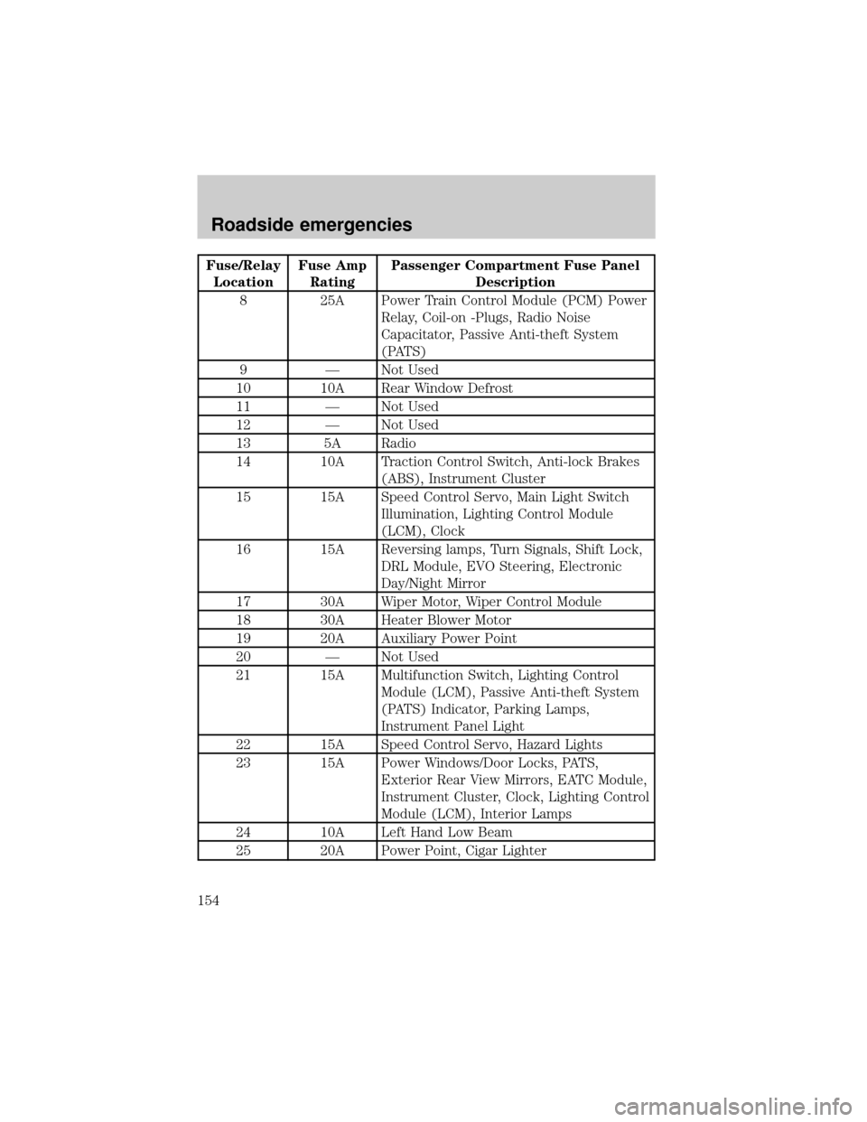
Fuse/Relay
LocationFuse Amp
RatingPassenger Compartment Fuse Panel
Description
8 25A Power Train Control Module (PCM) Power
Relay, Coil-on -Plugs, Radio Noise
Capacitator, Passive Anti-theft System
(PATS)
9 Ð Not Used
10 10A Rear Window Defrost
11 Ð Not Used
12 Ð Not Used
13 5A Radio
14 10A Traction Control Switch, Anti-lock Brakes
(ABS), Instrument Cluster
15 15A Speed Control Servo, Main Light Switch
Illumination, Lighting Control Module
(LCM), Clock
16 15A Reversing lamps, Turn Signals, Shift Lock,
DRL Module, EVO Steering, Electronic
Day/Night Mirror
17 30A Wiper Motor, Wiper Control Module
18 30A Heater Blower Motor
19 20A Auxiliary Power Point
20 Ð Not Used
21 15A Multifunction Switch, Lighting Control
Module (LCM), Passive Anti-theft System
(PATS) Indicator, Parking Lamps,
Instrument Panel Light
22 15A Speed Control Servo, Hazard Lights
23 15A Power Windows/Door Locks, PATS,
Exterior Rear View Mirrors, EATC Module,
Instrument Cluster, Clock, Lighting Control
Module (LCM), Interior Lamps
24 10A Left Hand Low Beam
25 20A Power Point, Cigar Lighter
Roadside emergencies
154
Page 155 of 240
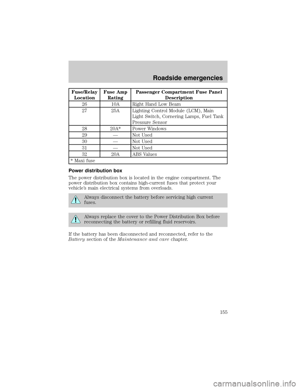
Fuse/Relay
LocationFuse Amp
RatingPassenger Compartment Fuse Panel
Description
26 10A Right Hand Low Beam
27 25A Lighting Control Module (LCM), Main
Light Switch, Cornering Lamps, Fuel Tank
Pressure Sensor
28 20A* Power Windows
29 Ð Not Used
30 Ð Not Used
31 Ð Not Used
32 20A ABS Values
* Maxi fuse
Power distribution box
The power distribution box is located in the engine compartment. The
power distribution box contains high-current fuses that protect your
vehicle's main electrical systems from overloads.
Always disconnect the battery before servicing high current
fuses.
Always replace the cover to the Power Distribution Box before
reconnecting the battery or refilling fluid reservoirs.
If the battery has been disconnected and reconnected, refer to the
Batterysection of theMaintenance and carechapter.
Roadside emergencies
155
Page 156 of 240
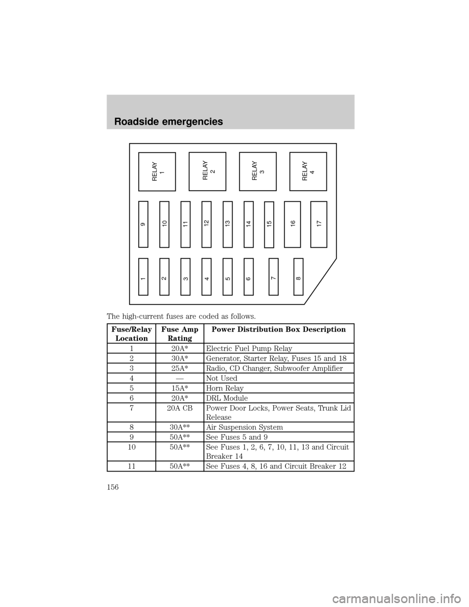
The high-current fuses are coded as follows.
Fuse/Relay
LocationFuse Amp
RatingPower Distribution Box Description
1 20A* Electric Fuel Pump Relay
2 30A* Generator, Starter Relay, Fuses 15 and 18
3 25A* Radio, CD Changer, Subwoofer Amplifier
4 Ð Not Used
5 15A* Horn Relay
6 20A* DRL Module
7 20A CB Power Door Locks, Power Seats, Trunk Lid
Release
8 30A** Air Suspension System
9 50A** See Fuses 5 and 9
10 50A** See Fuses 1, 2, 6, 7, 10, 11, 13 and Circuit
Breaker 14
11 50A** See Fuses 4, 8, 16 and Circuit Breaker 12
1
2
3
4
5
6
7
89
10
11
12
13
14
15
16
17RELAY
1
RELAY
2
RELAY
3
RELAY
4
Roadside emergencies
156
Page 157 of 240
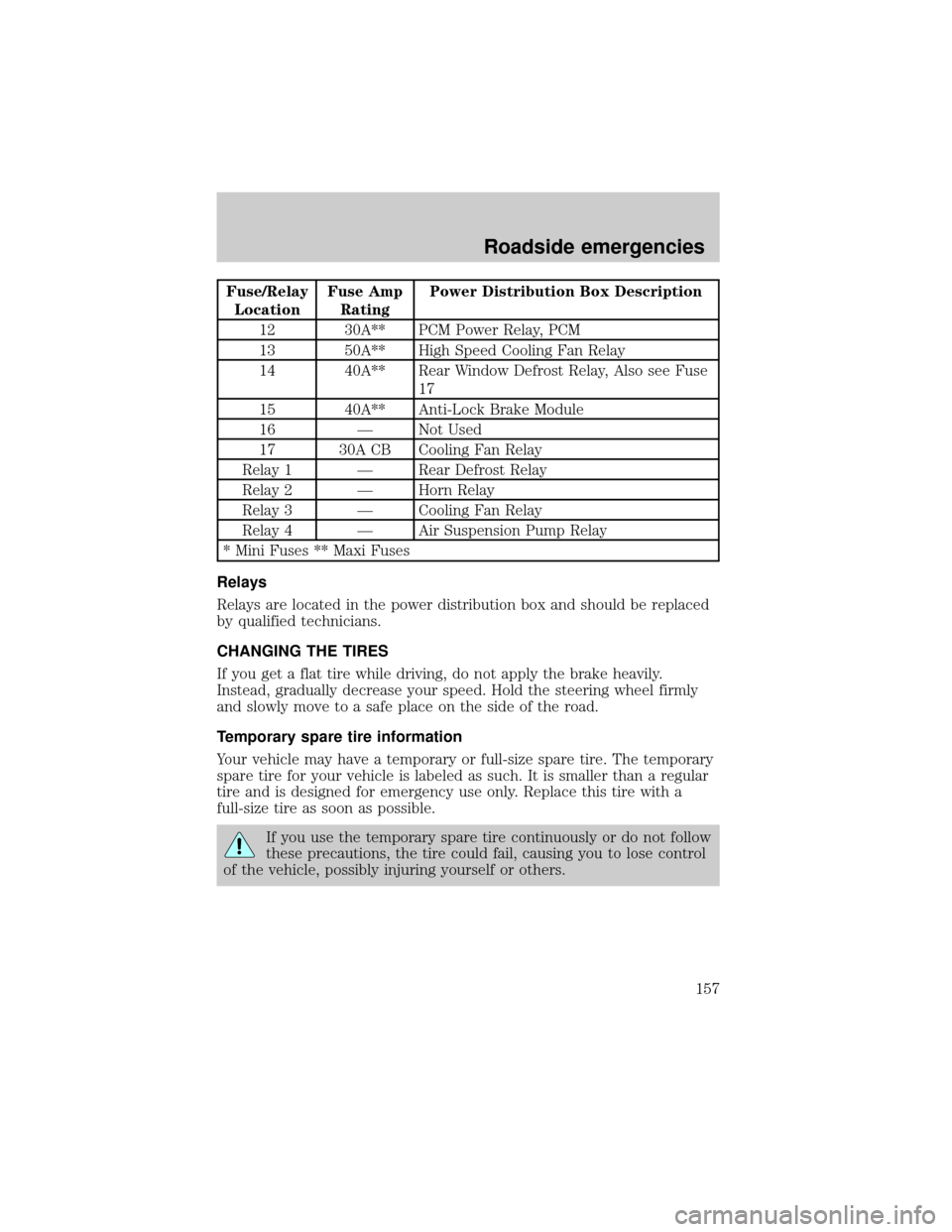
Fuse/Relay
LocationFuse Amp
RatingPower Distribution Box Description
12 30A** PCM Power Relay, PCM
13 50A** High Speed Cooling Fan Relay
14 40A** Rear Window Defrost Relay, Also see Fuse
17
15 40A** Anti-Lock Brake Module
16 Ð Not Used
17 30A CB Cooling Fan Relay
Relay 1 Ð Rear Defrost Relay
Relay 2 Ð Horn Relay
Relay 3 Ð Cooling Fan Relay
Relay 4 Ð Air Suspension Pump Relay
* Mini Fuses ** Maxi Fuses
Relays
Relays are located in the power distribution box and should be replaced
by qualified technicians.
CHANGING THE TIRES
If you get a flat tire while driving, do not apply the brake heavily.
Instead, gradually decrease your speed. Hold the steering wheel firmly
and slowly move to a safe place on the side of the road.
Temporary spare tire information
Your vehicle may have a temporary or full-size spare tire. The temporary
spare tire for your vehicle is labeled as such. It is smaller than a regular
tire and is designed for emergency use only. Replace this tire with a
full-size tire as soon as possible.
If you use the temporary spare tire continuously or do not follow
these precautions, the tire could fail, causing you to lose control
of the vehicle, possibly injuring yourself or others.
Roadside emergencies
157
Page 238 of 240

GVWR ......................................143
trailer towing ..........................143
Locks
autolock .....................................86
childproof ..................................83
doors ..........................................82
Lubricant specifications ...218±219
Lumbar support, seats .............102
M
Message center ...........................22
reset button ..............................23
select button .............................23
Mirrors
automatic dimming rearview
mirror ........................................78
cleaning ...................................212
side view mirrors (power) .......83
Motorcraft parts ................200, 216
O
Octane rating ............................198
Odometer .....................................19
Oil (see Engine oil) ..................171
Overdrive .............................68, 141
P
Panic alarm feature, remote
entry system ................................88
Parking brake ............................135
Parts (see Motorcraft parts) ....216
Passenger Occupant
Classification Sensor .................104
Pedals (see Power adjustable
foot pedals) .................................64Power distribution box
(see Fuses) ...............................155
Power door locks ..................82, 86
Power steering ..........................138
fluid, checking and adding ....183
fluid, refill capacity ................216
fluid, specifications .........218±219
R
Radio ............................................38
Rear window defroster ...............38
Relays ................................152, 157
Remote entry system ...........84, 88
illuminated entry ......................88
locking/unlocking doors ...........85
opening the trunk .....................87
panic alarm ...............................88
replacement/additional
transmitters ...............................89
replacing the batteries .............88
S
Safety belts (see Safety
restraints) ............16, 102, 106±110
Safety defects, reporting ..........233
Safety restraints ........102, 106±110
belt minder .............................112
cleaning the safety belts..115, 215
extension assembly ................111
for adults .........................107±109
for children .....................120±121
lap belt ....................................110
Occupant Classification
Sensor ......................................104
warning light and
chime ...................11, 16, 111±112
Safety seats for children ..........122
Index
238