transmission Mercury Marauder 2003 s Owner's Guide
[x] Cancel search | Manufacturer: MERCURY, Model Year: 2003, Model line: Marauder, Model: Mercury Marauder 2003Pages: 232, PDF Size: 2.29 MB
Page 146 of 232
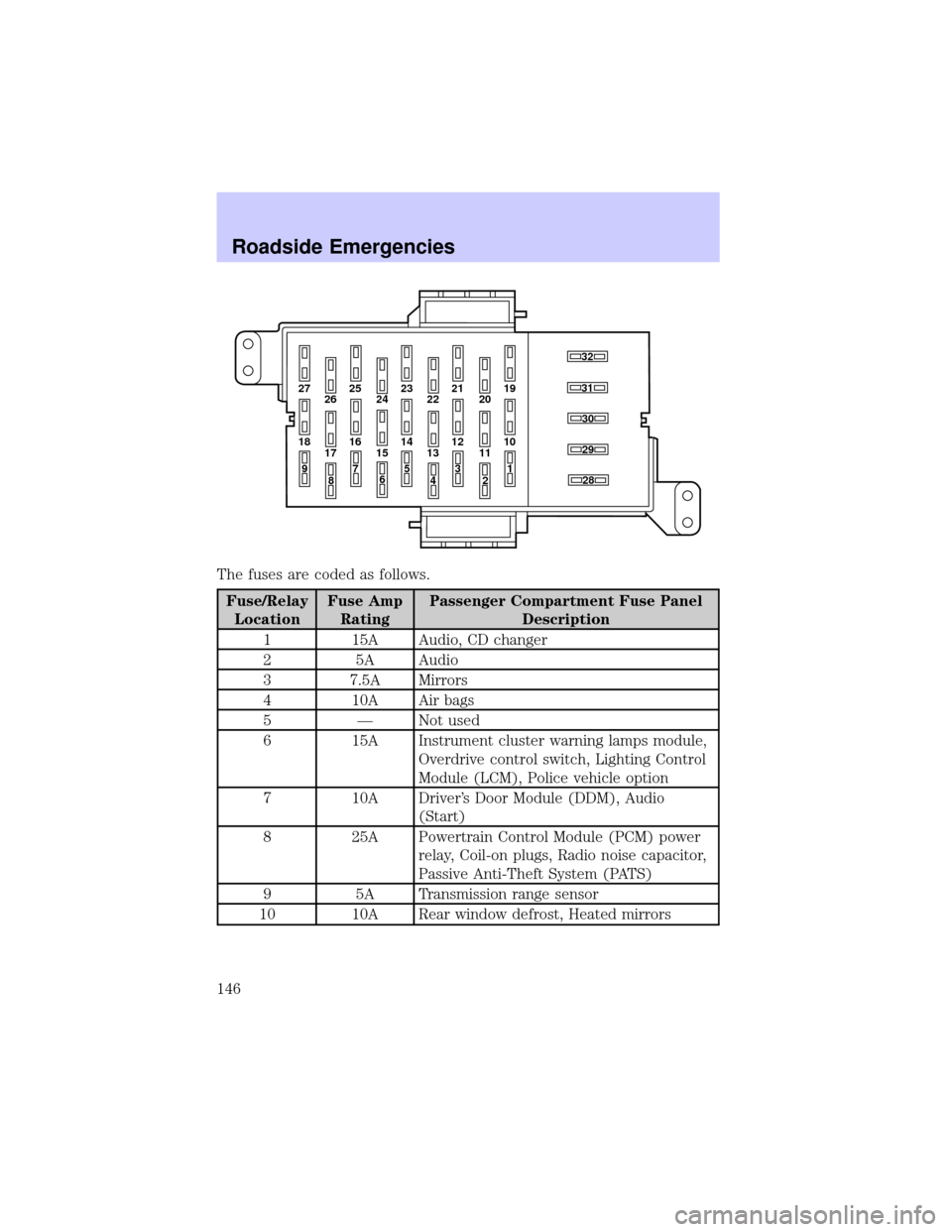
The fuses are coded as follows.
Fuse/Relay
LocationFuse Amp
RatingPassenger Compartment Fuse Panel
Description
1 15A Audio, CD changer
2 5A Audio
3 7.5A Mirrors
4 10A Air bags
5 Ð Not used
6 15A Instrument cluster warning lamps module,
Overdrive control switch, Lighting Control
Module (LCM), Police vehicle option
7 10A Driver's Door Module (DDM), Audio
(Start)
8 25A Powertrain Control Module (PCM) power
relay, Coil-on plugs, Radio noise capacitor,
Passive Anti-Theft System (PATS)
9 5A Transmission range sensor
10 10A Rear window defrost, Heated mirrors
27 25
26 2423 21
2219
20
18 16
17 1514 12
131030
32
31
28
29
11
97
8653
41
2
Roadside Emergencies
146
Page 156 of 232
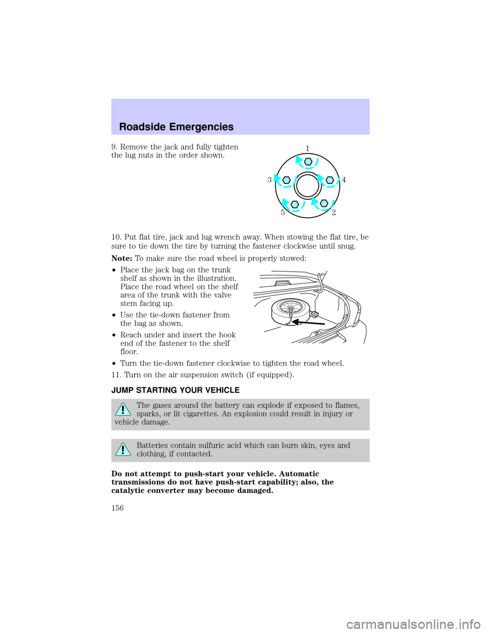
9. Remove the jack and fully tighten
the lug nuts in the order shown.
10. Put flat tire, jack and lug wrench away. When stowing the flat tire, be
sure to tie down the tire by turning the fastener clockwise until snug.
Note:To make sure the road wheel is properly stowed:
²Place the jack bag on the trunk
shelf as shown in the illustration.
Place the road wheel on the shelf
area of the trunk with the valve
stem facing up.
²Use the tie-down fastener from
the bag as shown.
²Reach under and insert the hook
end of the fastener to the shelf
floor.
²Turn the tie-down fastener clockwise to tighten the road wheel.
11. Turn on the air suspension switch (if equipped).
JUMP STARTING YOUR VEHICLE
The gases around the battery can explode if exposed to flames,
sparks, or lit cigarettes. An explosion could result in injury or
vehicle damage.
Batteries contain sulfuric acid which can burn skin, eyes and
clothing, if contacted.
Do not attempt to push-start your vehicle. Automatic
transmissions do not have push-start capability; also, the
catalytic converter may become damaged.
1
4 3
2 5
Roadside Emergencies
156
Page 157 of 232
Preparing your vehicle
When the battery is disconnected or a new battery is installed, the
transmission must relearn its shift strategy. As a result, the transmission
may have firm and/or soft shifts. This operation is considered normal and
will not affect function or durability of the transmission. Over time, the
adaptive learning process will fully update transmission operation.
1.Use only a 12±volt supply to start your vehicle.
2. Do not disconnect the battery of the disabled vehicle as this could
damage the vehicle's electrical system.
3. Park the booster vehicle close to the hood of the disabled vehicle
making sure the two vehiclesdo nottouch. Set the parking brake on
both vehicles and stay clear of the engine cooling fan and other moving
parts.
4. Check all battery terminals and remove any excessive corrosion before
you attach the battery cables. Ensure that vent caps are tight and level.
5. Turn the heater fan on in both vehicles to protect any electrical
surges. Turn all other accessories off.
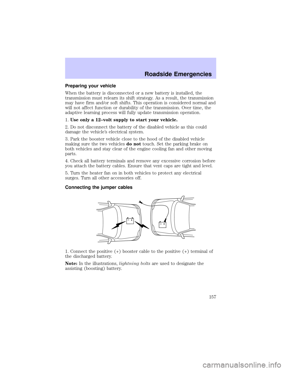
Connecting the jumper cables
1. Connect the positive (+) booster cable to the positive (+) terminal of
the discharged battery.
Note:In the illustrations,lightning boltsare used to designate the
assisting (boosting) battery.
+–+–
Roadside Emergencies
157
Page 181 of 232
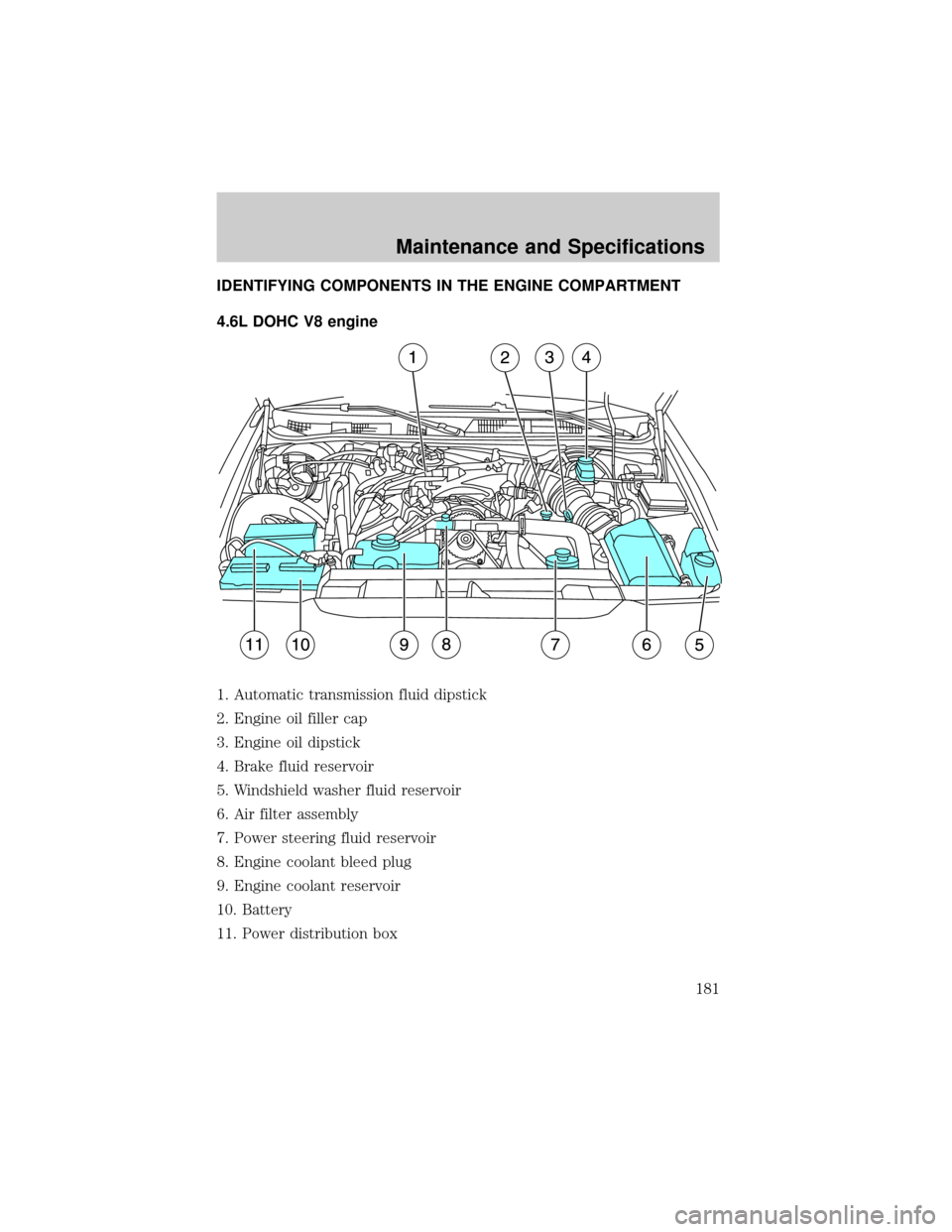
IDENTIFYING COMPONENTS IN THE ENGINE COMPARTMENT
4.6L DOHC V8 engine
1. Automatic transmission fluid dipstick
2. Engine oil filler cap
3. Engine oil dipstick
4. Brake fluid reservoir
5. Windshield washer fluid reservoir
6. Air filter assembly
7. Power steering fluid reservoir
8. Engine coolant bleed plug
9. Engine coolant reservoir
10. Battery
11. Power distribution box
Maintenance and Specifications
181
Page 201 of 232
²Perform all regularly scheduled maintenance items. Follow the
recommended maintenance schedule and owner maintenance checks
found in your vehicle scheduled maintenance guide.
Conditions
²Heavily loading a vehicle or towing a trailer may reduce fuel economy
at any speed.
²Carrying unnecessary weight may reduce fuel economy (approximately
0.4 km/L [1 mpg] is lost for every 180 kg [400 lb] of weight carried).
²Adding certain accessories to your vehicle (for example bug
deflectors, rollbars/light bars, running boards, ski/luggage racks) may
reduce fuel economy.
²Using fuel blended with alcohol may lower fuel economy.
²Fuel economy may decrease with lower temperatures during the first
12±16 km (8±10 miles) of driving.
²Driving on flat terrain offers improved fuel economy as compared to
driving on hilly terrain.
²Transmissions give their best fuel economy when operated in the top
cruise gear and with steady pressure on the gas pedal.
²Close windows for high speed driving.
EPA window sticker
Every new vehicle should have the EPA window sticker. Contact your
dealer if the window sticker is not supplied with your vehicle. The EPA
window sticker should be your guide for the fuel economy comparisons
with other vehicles.
It is important to note the box in the lower left corner of the window
sticker. These numbers represent the Range of L/100 km (MPG)
expected on the vehicle under optimum conditions. Your fuel economy
may vary depending upon the method of operation and conditions.
EMISSION CONTROL SYSTEM
Your vehicle is equipped with various emission control components and a
catalytic converter which will enable your vehicle to comply with
applicable exhaust emission standards. To make sure that the catalytic
converter and other emission control components continue to work
properly:
²Use only the specified fuel listed.
²Avoid running out of fuel.
Maintenance and Specifications
201
Page 204 of 232
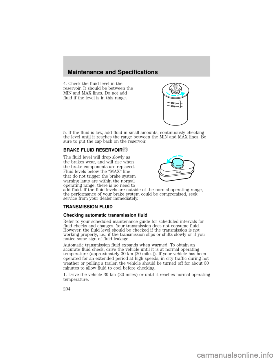
4. Check the fluid level in the
reservoir. It should be between the
MIN and MAX lines. Do not add
fluid if the level is in this range.
5. If the fluid is low, add fluid in small amounts, continuously checking
the level until it reaches the range between the MIN and MAX lines. Be
sure to put the cap back on the reservoir.
BRAKE FLUID RESERVOIR
The fluid level will drop slowly as
the brakes wear, and will rise when
the brake components are replaced.
Fluid levels below the ªMAXº line
that do not trigger the brake system
warning lamp are within the normal
operating range, there is no need to
add fluid. If the fluid levels are outside of the normal operating range,
the performance of your brake system could be compromised, seek
service from your dealer immediately.
TRANSMISSION FLUID
Checking automatic transmission fluid
Refer to your scheduled maintenance guide for scheduled intervals for
fluid checks and changes. Your transmission does not consume fluid.
However, the fluid level should be checked if the transmission is not
working properly, i.e., if the transmission slips or shifts slowly or if you
notice some sign of fluid leakage.
Automatic transmission fluid expands when warmed. To obtain an
accurate fluid check, drive the vehicle until it is at normal operating
temperature (approximately 30 km [20 miles]). If your vehicle has been
operated for an extended period at high speeds, in city traffic during hot
weather or pulling a trailer, the vehicle should be turned off for about 30
minutes to allow fluid to cool before checking.
1. Drive the vehicle 30 km (20 miles) or until it reaches normal operating
temperature.
DONOTOVERFILLPOWERSTEERINGFLUID
MAX
MIN
MAX
Maintenance and Specifications
204
Page 205 of 232
2. Park the vehicle on a level surface and engage the parking brake.
3. With the parking brake engaged and your foot on the brake pedal,
start the engine and move the gearshift lever through all of the gear
ranges. Allow sufficient time for each gear to engage.
4. Latch the gearshift lever in P (Park) and leave the engine running.
5. Remove the dipstick, wiping it clean with a clean, dry lint free rag. If
necessary, refer toIdentifying components in the engine compartment
in this chapter for the location of the dipstick.
6. Install the dipstick making sure it is fully seated in the filler tube.
7. Remove the dipstick and inspect the fluid level. The fluid should be in
the designated area for normal operating temperature or ambient
temperature.
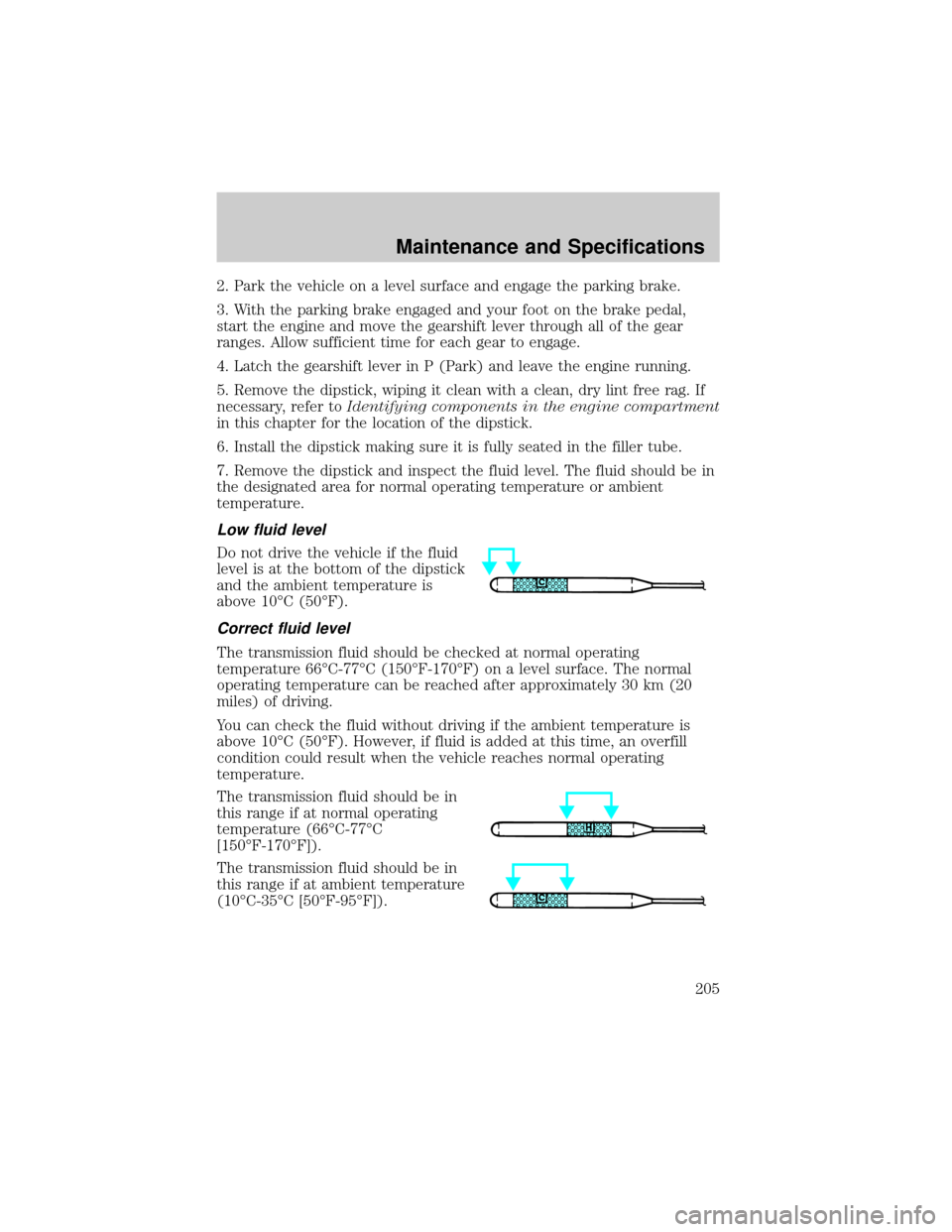
Low fluid level
Do not drive the vehicle if the fluid
level is at the bottom of the dipstick
and the ambient temperature is
above 10ÉC (50ÉF).
Correct fluid level
The transmission fluid should be checked at normal operating
temperature 66ÉC-77ÉC (150ÉF-170ÉF) on a level surface. The normal
operating temperature can be reached after approximately 30 km (20
miles) of driving.
You can check the fluid without driving if the ambient temperature is
above 10ÉC (50ÉF). However, if fluid is added at this time, an overfill
condition could result when the vehicle reaches normal operating
temperature.
The transmission fluid should be in
this range if at normal operating
temperature (66ÉC-77ÉC
[150ÉF-170ÉF]).
The transmission fluid should be in
this range if at ambient temperature
(10ÉC-35ÉC [50ÉF-95ÉF]).
Maintenance and Specifications
205
Page 206 of 232
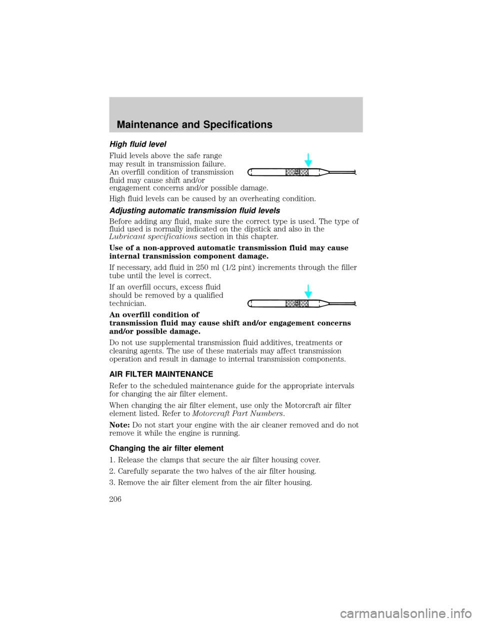
High fluid level
Fluid levels above the safe range
may result in transmission failure.
An overfill condition of transmission
fluid may cause shift and/or
engagement concerns and/or possible damage.
High fluid levels can be caused by an overheating condition.
Adjusting automatic transmission fluid levels
Before adding any fluid, make sure the correct type is used. The type of
fluid used is normally indicated on the dipstick and also in the
Lubricant specificationssection in this chapter.
Use of a non-approved automatic transmission fluid may cause
internal transmission component damage.
If necessary, add fluid in 250 ml (1/2 pint) increments through the filler
tube until the level is correct.
If an overfill occurs, excess fluid
should be removed by a qualified
technician.
An overfill condition of
transmission fluid may cause shift and/or engagement concerns
and/or possible damage.
Do not use supplemental transmission fluid additives, treatments or
cleaning agents. The use of these materials may affect transmission
operation and result in damage to internal transmission components.
AIR FILTER MAINTENANCE
Refer to the scheduled maintenance guide for the appropriate intervals
for changing the air filter element.
When changing the air filter element, use only the Motorcraft air filter
element listed. Refer toMotorcraft Part Numbers.
Note:Do not start your engine with the air cleaner removed and do not
remove it while the engine is running.
Changing the air filter element
1. Release the clamps that secure the air filter housing cover.
2. Carefully separate the two halves of the air filter housing.
3. Remove the air filter element from the air filter housing.
Maintenance and Specifications
206
Page 211 of 232
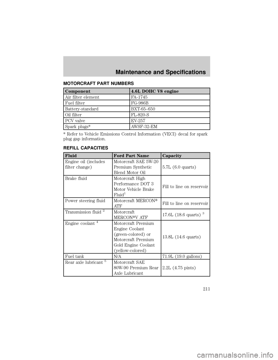
MOTORCRAFT PART NUMBERS
Component 4.6L DOHC V8 engine
Air filter element FA-1745
Fuel filter FG-986B
Battery-standard BXT-65±650
Oil filter FL-820-S
PCV valve EV-257
Spark plugs* AWSF-32-EM
* Refer to Vehicle Emissions Control Information (VECI) decal for spark
plug gap information.
REFILL CAPACITIES
Fluid Ford Part Name Capacity
Engine oil (includes
filter change)Motorcraft SAE 5W-20
Premium Synthetic
Blend Motor Oil5.7L (6.0 quarts)
Brake fluid Motorcraft High
Performance DOT 3
Motor Vehicle Brake
Fluid
1
Fill to line on reservoir
Power steering fluid Motorcraft MERCONt
AT FFill to line on reservoir
Transmission fluid
2Motorcraft
MERCONtVATF17.6L (18.6 quarts)3
Engine coolant4Motorcraft Premium
Engine Coolant
(green-colored) or
Motorcraft Premium
Gold Engine Coolant
(yellow-colored)13.8L (14.6 quarts)
Fuel tank N/A 71.9L (19.0 gallons)
Rear axle lubricant
5Motorcraft SAE
80W-90 Premium Rear
Axle Lubricant2.2L (4.75 pints)
Maintenance and Specifications
211
Page 212 of 232
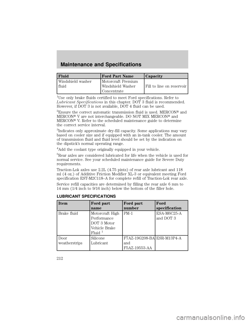
Fluid Ford Part Name Capacity
Windshield washer
fluidMotorcraft Premium
Windshield Washer
ConcentrateFill to line on reservoir
1Use only brake fluids certified to meet Ford specifications. Refer to
Lubricant Specificationsin this chapter. DOT 3 fluid is recommended.
However, if DOT 3 is not available, DOT 4 fluid can be used.
2Ensure the correct automatic transmission fluid is used. MERCONtand
MERCONtV are not interchangeable. DO NOT MIX MERCONtand
MERCONtV. Refer to the scheduled maintenance guide to determine
the correct service interval.
3Indicates only approximate dry-fill capacity. Some applications may vary
based on cooler size and if equipped with an in-tank cooler. The amount
of transmission fluid and fluid level should be set by the indication on
the dipstick's normal operating range.
4Add the coolant type originally equipped in your vehicle.
5Rear axles are considered lubricated for life when the vehicle is used for
normal service. See your scheduled maintenance guide for Severe Duty
requirements.
Traction-Lok axles use 2.2L (4.75 pints) of rear axle lubricant and 118
ml (4 oz.) of Additive Friction Modifier XL-3 or equivalent meeting Ford
specification EST-M2C118±A for complete refill of Traction-Lok rear axle.
Service refill capacities are determined by filling the rear axle 6 mm to
14 mm (1/4 inch to 9/16 inch) below the bottom of the filler hole.
LUBRICANT SPECIFICATIONS
Item Ford part
nameFord part
numberFord
specification
Brake fluid Motorcraft High
Performance
DOT 3 Motor
Vehicle Brake
Fluid
1
PM-1 ESA-M6C25-A
and DOT 3
Door
weatherstripsSilicone
LubricantF7AZ-19G208-BA
and
F5AZ-19553-AAESR-M13P4-A
Maintenance and Specifications
212