ignition Mercury Marauder 2003 s Owner's Guide
[x] Cancel search | Manufacturer: MERCURY, Model Year: 2003, Model line: Marauder, Model: Mercury Marauder 2003Pages: 232, PDF Size: 2.29 MB
Page 122 of 232
STARTING
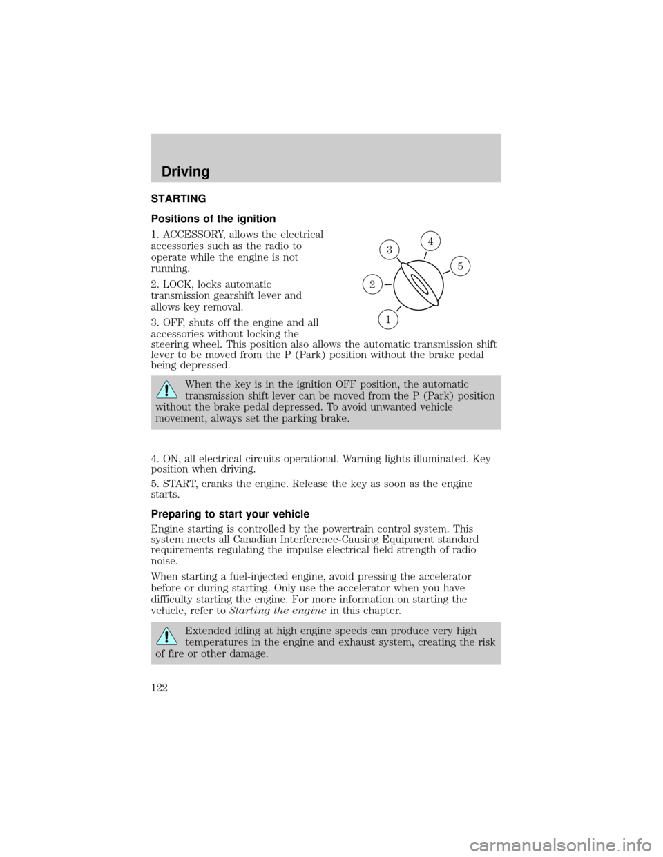
Positions of the ignition
1. ACCESSORY, allows the electrical
accessories such as the radio to
operate while the engine is not
running.
2. LOCK, locks automatic
transmission gearshift lever and
allows key removal.
3. OFF, shuts off the engine and all
accessories without locking the
steering wheel. This position also allows the automatic transmission shift
lever to be moved from the P (Park) position without the brake pedal
being depressed.
When the key is in the ignition OFF position, the automatic
transmission shift lever can be moved from the P (Park) position
without the brake pedal depressed. To avoid unwanted vehicle
movement, always set the parking brake.
4. ON, all electrical circuits operational. Warning lights illuminated. Key
position when driving.
5. START, cranks the engine. Release the key as soon as the engine
starts.
Preparing to start your vehicle
Engine starting is controlled by the powertrain control system. This
system meets all Canadian Interference-Causing Equipment standard
requirements regulating the impulse electrical field strength of radio
noise.
When starting a fuel-injected engine, avoid pressing the accelerator
before or during starting. Only use the accelerator when you have
difficulty starting the engine. For more information on starting the
vehicle, refer toStarting the enginein this chapter.
Extended idling at high engine speeds can produce very high
temperatures in the engine and exhaust system, creating the risk
of fire or other damage.
3
1
2
5
4
Driving
122
Page 127 of 232
Using ABS
²In an emergency or when maximum efficiency from the four-wheel
ABS is required, apply continuous force on the brake. The four wheel
ABS will be activated immediately, thus allowing you to retain full
steering control of your vehicle and, providing there is sufficient
space, will enable you to avoid obstacles and bring the vehicle to a
controlled stop.
²The anti-lock system does not reduce stopping distance. Always leave
enough room between your vehicle and the vehicle in front of you to
stop.
²We recommend that you familiarize yourself with this braking
technique. However, avoid taking any unnecessary risks.
ABS warning lampABS
TheABSwarning lamp in the instrument cluster momentarily illuminates
when the ignition is turned to the ON position. If the light does not
illuminate momentarily at start up, remains on or continues to flash, the
ABS needs to be serviced.
With the ABS light on, the anti-lock
brake system is disabled and normal
braking is still effective unless the
brake warning light also remains
illuminated with parking brake
released. (If your brake warning lamp illuminates, have your vehicle
serviced immediately.)
Parking brake
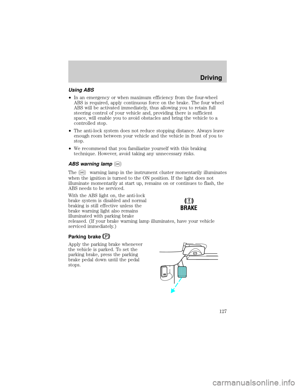
Apply the parking brake whenever
the vehicle is parked. To set the
parking brake, press the parking
brake pedal down until the pedal
stops.
!
BRAKE
HOOD
Driving
127
Page 128 of 232
The BRAKE warning lamp in the
instrument cluster illuminates and
remains illuminated (when the
ignition is turned ON) until the
parking brake is released.
Always set the parking brake fully and make sure that the
gearshift is securely latched in P (Park).
The parking brake is not recommended to stop a moving vehicle.
However, if the normal brakes fail, the parking brake can be used to stop
your vehicle in an emergency. Since the parking brake applies only the
rear brakes, the vehicle's stopping distance will increase greatly and the
handling of your vehicle will be adversely affected.
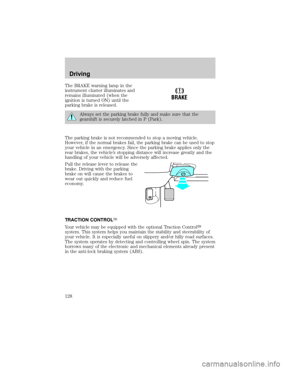
Pull the release lever to release the
brake. Driving with the parking
brake on will cause the brakes to
wear out quickly and reduce fuel
economy.
TRACTION CONTROLY
Your vehicle may be equipped with the optional Traction Controly
system. This system helps you maintain the stability and steerability of
your vehicle. It is especially useful on slippery and/or hilly road surfaces.
The system operates by detecting and controlling wheel spin. The system
borrows many of the electronic and mechanical elements already present
in the anti-lock braking system (ABS).
!
BRAKE
Driving
128
Page 129 of 232
Wheel-speed sensors allow excess rear wheel spin to be detected by the
Traction Controlyportion of the ABS computer. Any excessive wheel
spin is controlled by automatically applying and releasing the rear brakes
in conjunction with engine torque reductions. Engine torque reduction is
realized via the fully electronic spark and fuel injection systems. This
process is very sensitive to driving conditions and very fast acting. The
rear wheels ªsearchº for optimum traction several times a second and
adjustments are made accordingly.
The Traction Controlysystem will allow your vehicle to make better use
of available traction on slippery surfaces. The system is a driver aid
which makes your vehicle easier to handle primarily on snow and ice
covered roads.
During Traction Controlyoperation you may hear an electric motor type
of sound coming from the engine compartment and the engine will not
ªrev-upº when you push further on the accelerator. This is normal
system behavior.
If you should become stuck in snow
or ice or on a very slippery road
surface, try switching the Traction
Controlysystem off. This may allow
excess wheel spin to ªdigº the
vehicle out and enable a successful
ªrockingº maneuver.
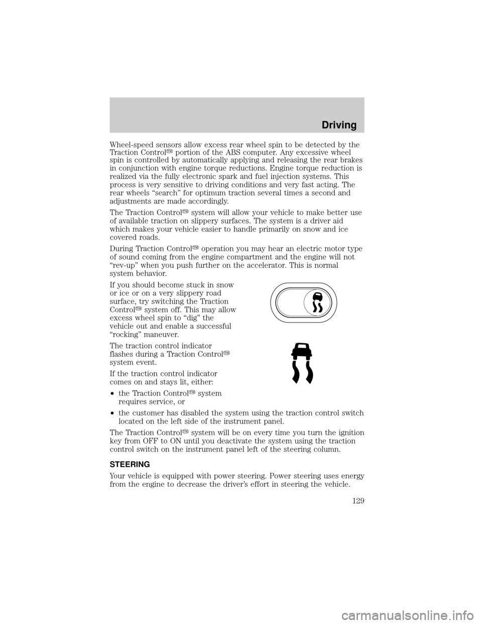
The traction control indicator
flashes during a Traction Controly
system event.
If the traction control indicator
comes on and stays lit, either:
²the Traction Controlysystem
requires service, or
²the customer has disabled the system using the traction control switch
located on the left side of the instrument panel.
The Traction Controlysystem will be on every time you turn the ignition
key from OFF to ON until you deactivate the system using the traction
control switch on the instrument panel left of the steering column.
STEERING
Your vehicle is equipped with power steering. Power steering uses energy
from the engine to decrease the driver's effort in steering the vehicle.
Driving
129
Page 131 of 232
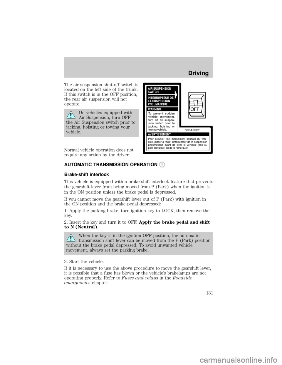
The air suspension shut-off switch is
located on the left side of the trunk.
If this switch is in the OFF position,
the rear air suspension will not
operate.
On vehicles equipped with
Air Suspension, turn OFF
the Air Suspension switch prior to
jacking, hoisting or towing your
vehicle.
Normal vehicle operation does not
require any action by the driver.
AUTOMATIC TRANSMISSION OPERATION
Brake-shift interlock
This vehicle is equipped with a brake-shift interlock feature that prevents
the gearshift lever from being moved from P (Park) when the ignition is
in the ON position unless the brake pedal is depressed.
If you cannot move the gearshift lever out of P (Park) with ignition in
the ON position and the brake pedal depressed:
1. Apply the parking brake, turn ignition key to LOCK, then remove the
key.
2. Insert the key and turn it to OFF.Apply the brake pedal and shift
to N (Neutral).
When the key is in the ignition OFF position, the automatic
transmission shift lever can be moved from the P (Park) position
without the brake pedal depressed. To avoid unwanted vehicle
movement, always set the parking brake.
3. Start the vehicle.
If it is necessary to use the above procedure to move the gearshift lever,
it is possible that a fuse has blown or the vehicle's brakelamps are not
operating properly. Refer toFuses and relaysin theRoadside
emergencieschapter.
AIR SUSPENSION
SWITCH
INTERRUPTEUR DE
LA SUSPENSION
PNEUMATIQUE
WARNING
AVERTISSEMENTOFF-ARRET
To prevent sudden
vehicle movement,
turn off air suspen-
sion switch prior to
jacking, hoisting or
towing vehicle.
Pour prévenir tout mouvement soudain du véhi-
cule, placer à l'arrêt l'interrupteur de la suspension
pneumatique avant de lever le véhicule (cric ou
pont élévateur) ou de le remorquer.
OFF
Driving
131
Page 132 of 232
Do not drive your vehicle until you verify that the brakelamps
are working.
Always set the parking brake fully and make sure the gearshift is
latched in P (Park). Turn the ignition to the LOCK position and
remove the key whenever you leave your vehicle.
If the parking brake is fully released, but the brake warning lamp
remains illuminated, the brakes may not be working properly.
See your dealer or a qualified service technician.
Driving with a 4±speed automatic transmission
Understanding gearshift positions
To put your vehicle in gear, start the engine, depress the brake pedal,
then move gearshift lever out of P (Park).
Hold the brake pedal down while you move the gearshift lever
from P (Park) to another position. If you do not hold the brake
pedal down, your vehicle may move unexpectedly and injure someone.
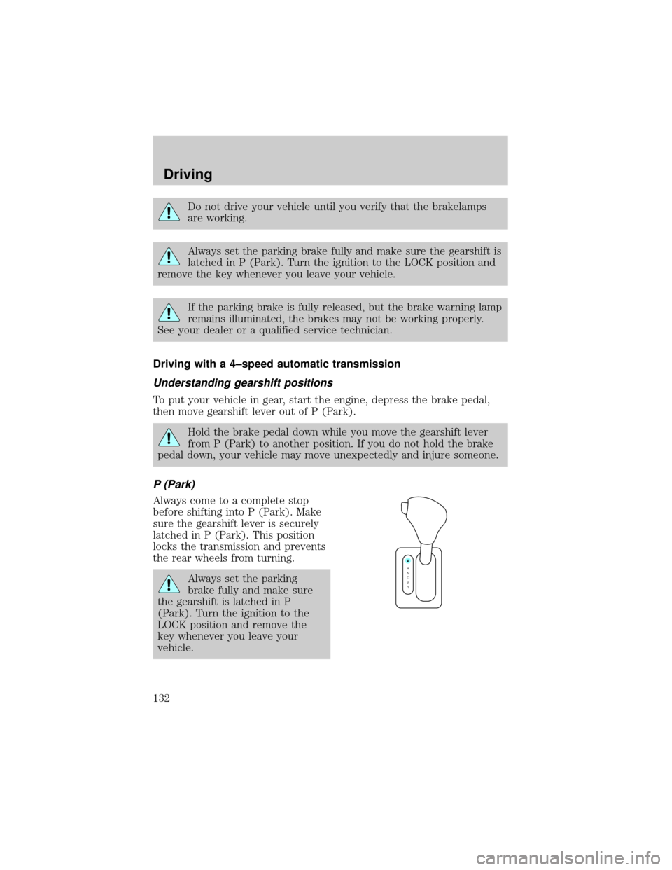
P (Park)
Always come to a complete stop
before shifting into P (Park). Make
sure the gearshift lever is securely
latched in P (Park). This position
locks the transmission and prevents
the rear wheels from turning.
Always set the parking
brake fully and make sure
the gearshift is latched in P
(Park). Turn the ignition to the
LOCK position and remove the
key whenever you leave your
vehicle.
P
R
N
D
2
1
Driving
132
Page 136 of 232

Extended use of other than the manufacturer's specified size tires on a
limited slip rear axle could result in a permanent reduction in
effectiveness. This loss of effectiveness does not affect normal driving
and should not be noticeable to the driver.
DRIVING THROUGH WATER
Do not drive quickly through standing water, especially if the depth is
unknown. Traction or brake capability may be limited and if the ignition
system gets wet, your engine may stall. Water may also enter your
engine's air intake and severely damage your engine.
If driving through deep or standing water is unavoidable, proceed very
slowly. Never drive through water that is higher than the bottom of the
hubs (for trucks) or the bottom of the wheel rims (for cars).
Once through the water, always try the brakes. Wet brakes do not stop
the vehicle as effectively as dry brakes. Drying can be improved by
moving your vehicle slowly while applying light pressure on the brake
pedal.
Driving through deep water where the transmission vent tube is
submerged may allow water into the transmission and cause
internal transmission damage. Have the fluid checked and, if
water is found, replace the fluid.
VEHICLE LOADING
Before loading a vehicle, familiarize yourself with the following terms:
²Base Curb Weight:Weight of the vehicle including any standard
equipment, fluids, lubricants, etc. It does not include occupants or
aftermarket equipment.
²Payload:Combined maximum allowable weight of cargo, occupants
and optional equipment. The payload equals the gross vehicle weight
rating minus base curb weight.
²GVW (Gross Vehicle Weight):Base curb weight plus payload
weight. The GVW is not a limit or a specification.
²GVWR (Gross Vehicle Weight Rating):Maximum permissible total
weight of the base vehicle, occupants, optional equipment and cargo.
The GVWR is specific to each vehicle and is listed on the Safety
Certification Label on the driver's door pillar.
²GAWR (Gross Axle Weight Rating):Carrying capacity for each axle
system. The GAWR is specific to each vehicle and is listed on the
Safety Certification Label on the driver's door pillar.
Driving
136
Page 143 of 232
Canadian customers who require roadside assistance, call
1±800±665±2006.
If you need to arrange roadside assistance for yourself, Ford Motor
Company will reimburse a reasonable amount. To obtain reimbursement
information, U.S. Ford or Mercury vehicles customers call
1-800-241-3673; Lincoln vehicle customers call 1±800±521±4140.
Canadian customers who need to obtain reimbursement information, call
1±800±665±2006.
ROADSIDE COVERAGE BEYOND BASIC WARRANTY
In the United States, you may purchase additional roadside assistance
coverage beyond this period through the Ford Auto Club by contacting
your Ford or Lincoln Mercury dealer.
Similarly in Canada, for uninterrupted Roadside Assistance coverage, you
may purchase extended coverage prior to your Basic Warranty's Roadside
Assistance expiring. For more information and enrollment, contact
1±877±294±2582 or visit our website at www.ford.ca.
HAZARD FLASHER
Use only in an emergency to warn traffic of vehicle breakdown,
approaching danger, etc. The hazard flashers can be operated when the
ignition is off.
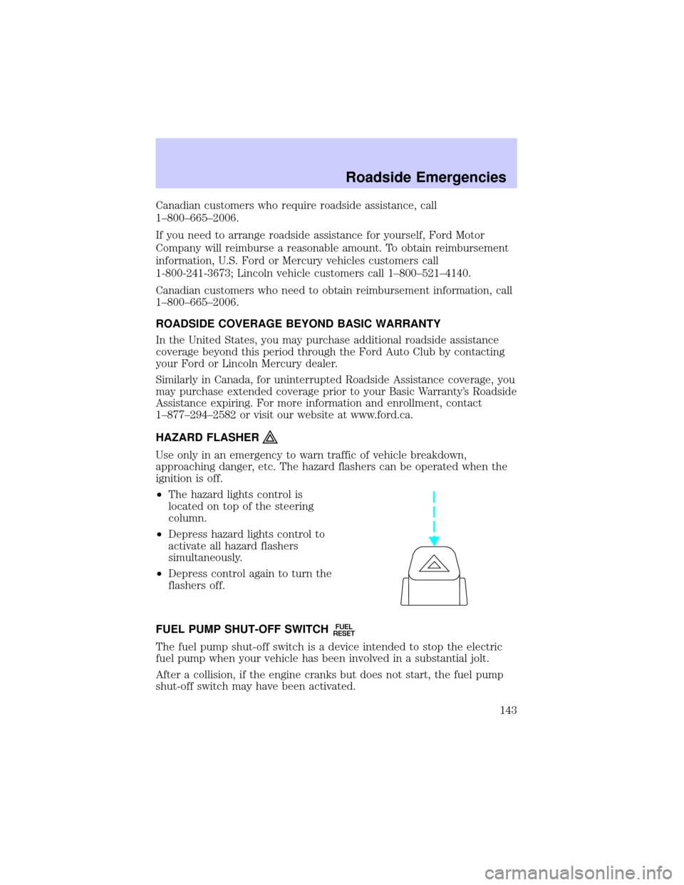
²The hazard lights control is
located on top of the steering
column.
²Depress hazard lights control to
activate all hazard flashers
simultaneously.
²Depress control again to turn the
flashers off.
FUEL PUMP SHUT-OFF SWITCH
FUEL
RESET
The fuel pump shut-off switch is a device intended to stop the electric
fuel pump when your vehicle has been involved in a substantial jolt.
After a collision, if the engine cranks but does not start, the fuel pump
shut-off switch may have been activated.
Roadside Emergencies
143
Page 144 of 232
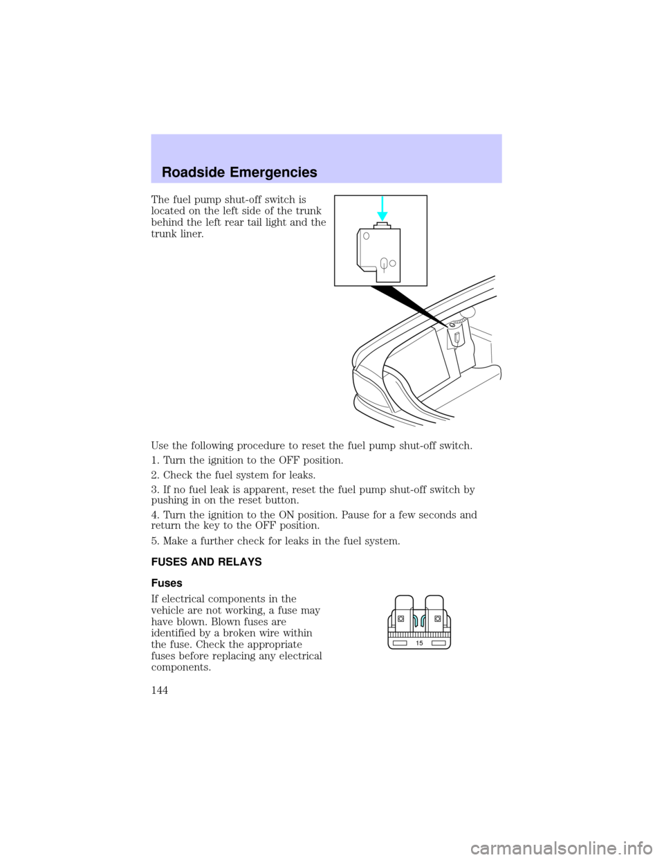
The fuel pump shut-off switch is
located on the left side of the trunk
behind the left rear tail light and the
trunk liner.
Use the following procedure to reset the fuel pump shut-off switch.
1. Turn the ignition to the OFF position.
2. Check the fuel system for leaks.
3. If no fuel leak is apparent, reset the fuel pump shut-off switch by
pushing in on the reset button.
4. Turn the ignition to the ON position. Pause for a few seconds and
return the key to the OFF position.
5. Make a further check for leaks in the fuel system.
FUSES AND RELAYS
Fuses
If electrical components in the
vehicle are not working, a fuse may
have blown. Blown fuses are
identified by a broken wire within
the fuse. Check the appropriate
fuses before replacing any electrical
components.
15
Roadside Emergencies
144
Page 149 of 232
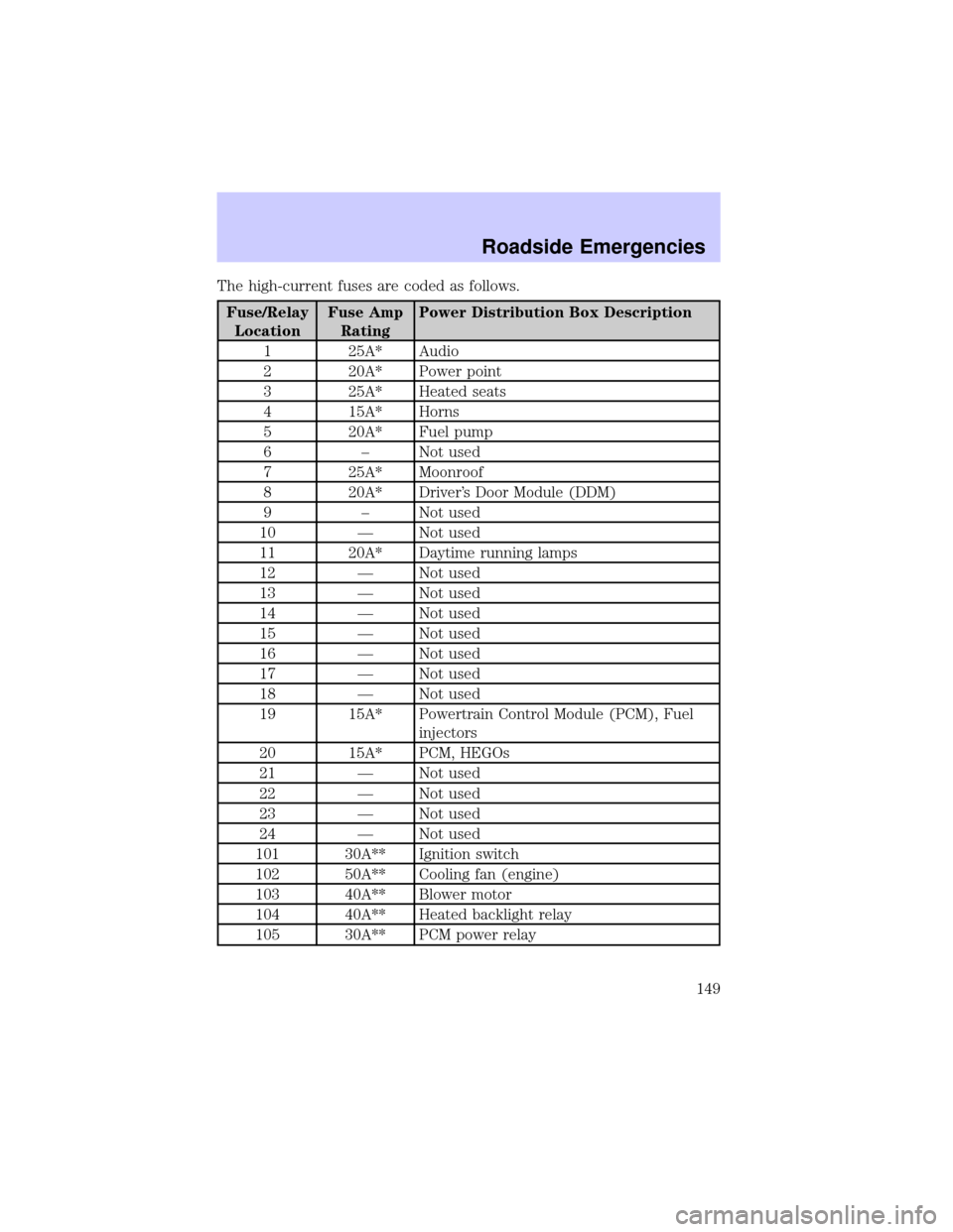
The high-current fuses are coded as follows.
Fuse/Relay
LocationFuse Amp
RatingPower Distribution Box Description
1 25A* Audio
2 20A* Power point
3 25A* Heated seats
4 15A* Horns
5 20A* Fuel pump
6 ± Not used
7 25A* Moonroof
8 20A* Driver's Door Module (DDM)
9 ± Not used
10 Ð Not used
11 20A* Daytime running lamps
12 Ð Not used
13 Ð Not used
14 Ð Not used
15 Ð Not used
16 Ð Not used
17 Ð Not used
18 Ð Not used
19 15A* Powertrain Control Module (PCM), Fuel
injectors
20 15A* PCM, HEGOs
21 Ð Not used
22 Ð Not used
23 Ð Not used
24 Ð Not used
101 30A** Ignition switch
102 50A** Cooling fan (engine)
103 40A** Blower motor
104 40A** Heated backlight relay
105 30A** PCM power relay
Roadside Emergencies
149