tow Mercury Marauder 2003 Owner's Manuals
[x] Cancel search | Manufacturer: MERCURY, Model Year: 2003, Model line: Marauder, Model: Mercury Marauder 2003Pages: 232, PDF Size: 2.29 MB
Page 2 of 232
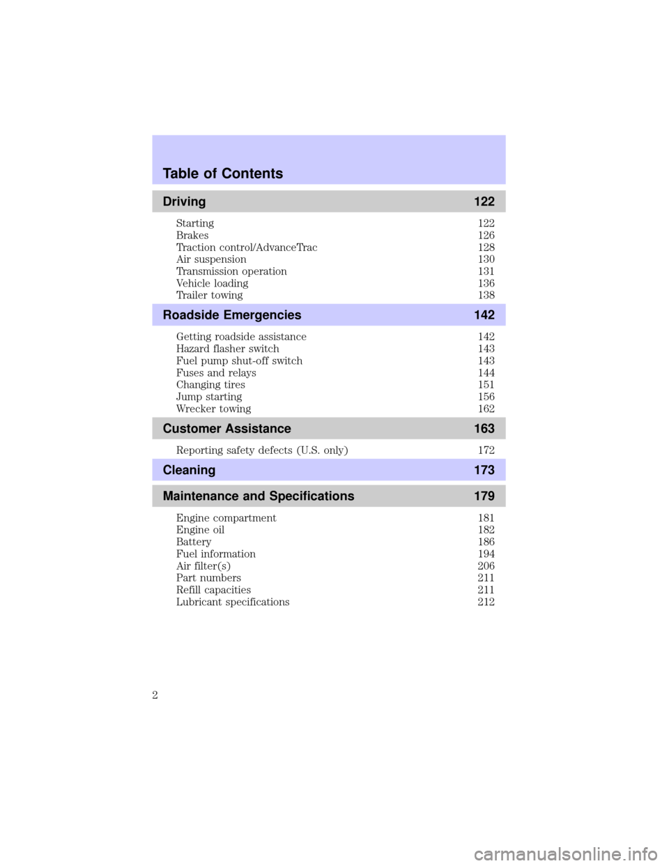
Driving 122
Starting 122
Brakes 126
Traction control/AdvanceTrac 128
Air suspension 130
Transmission operation 131
Vehicle loading 136
Trailer towing 138
Roadside Emergencies 142
Getting roadside assistance 142
Hazard flasher switch 143
Fuel pump shut-off switch 143
Fuses and relays 144
Changing tires 151
Jump starting 156
Wrecker towing 162
Customer Assistance 163
Reporting safety defects (U.S. only) 172
Cleaning 173
Maintenance and Specifications 179
Engine compartment 181
Engine oil 182
Battery 186
Fuel information 194
Air filter(s) 206
Part numbers 211
Refill capacities 211
Lubricant specifications 212
Table of Contents
2
Page 5 of 232
Fuel pump shut-off switchIn the event of an accident the
safety switch will automatically cut off the fuel supply to the
engine. The switch can also be activated through sudden vibration (e.g.
collision when parking). To reset the switch, refer to theFuel pump
shut-off switchin theRoadside emergencieschapter.
SAFETY AND ENVIRONMENT PROTECTION
Warning symbols in this guide
How can you reduce the risk of personal injury and prevent possible
damage to others, your vehicle and its equipment? In this guide, answers
to such questions are contained in comments highlighted by the warning
triangle symbol. These comments should be read and observed.
Warning symbols on your vehicle
When you see this symbol, it is
imperative that you consult the
relevant section of this guide before
touching or attempting adjustment
of any kind.
Protecting the environment
We must all play our part in
protecting the environment. Correct
vehicle usage and the authorized
disposal of waste cleaning and
lubrication materials are significant
steps towards this aim. Information in this respect is highlighted in this
guide with the tree symbol.
Introduction
5
Page 6 of 232

BREAKING-IN YOUR VEHICLE
Your vehicle does not need an extensive break-in. Try not to drive
continuously at the same speed for the first 1,600 km (1,000 miles) of
new vehicle operation. Vary your speed to allow parts to adjust
themselves to other parts.
Drive your new vehicle at least 800 km (500 miles) before towing a
trailer.
Do not add friction modifier compounds or special break-in oils during
the first few thousand kilometers (miles) of operation, since these
additives may prevent piston ring seating. SeeEngine oilin the
Maintenance and specificationschapter for more information on oil
usage.
SPECIAL NOTICES
Emission warranty
The New Vehicle Limited Warranty includes Bumper-to-Bumper
Coverage, Safety Restraint Coverage, Corrosion Coverage, and 7.3L
Power Stroke Diesel Engine Coverage. In addition, your vehicle is eligible
for Emissions Defect and Emissions Performance Warranties. For a
detailed description of what is covered and what is not covered, refer to
theWarranty Guidethat is provided to you along with your Owner's
Guide.
Data Recording
Computers in your vehicle are capable of recording detailed data
potentially including but not limited to information such as:
²the use of restraint systems including seat belts by the driver and
passengers,
²information about the performance of various systems and modules in
the vehicle, and
²information related to engine, throttle, steering, brake or other system
status.
Introduction
6
Page 10 of 232
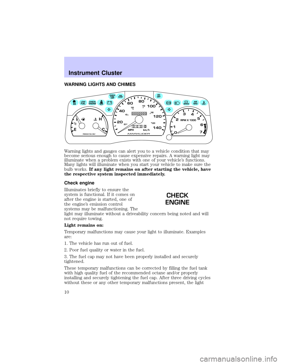
WARNING LIGHTS AND CHIMES
Warning lights and gauges can alert you to a vehicle condition that may
become serious enough to cause expensive repairs. A warning light may
illuminate when a problem exists with one of your vehicle's functions.
Many lights will illuminate when you start your vehicle to make sure the
bulb works.If any light remains on after starting the vehicle, have
the respective system inspected immediately.
Check engine
Illuminates briefly to ensure the
system is functional. If it comes on
after the engine is started, one of
the engine's emission control
systems may be malfunctioning. The
light may illuminate without a driveability concern being noted and will
not require towing.
Light remains on:
Temporary malfunctions may cause your light to illuminate. Examples
are:
1. The vehicle has run out of fuel.
2. Poor fuel quality or water in the fuel.
3. The fuel cap may not have been properly installed and securely
tightened.
These temporary malfunctions can be corrected by filling the fuel tank
with high quality fuel of the recommended octane and/or properly
installing and securely tightening the fuel cap. After three driving cycles
without these or any other temporary malfunctions present, the light
CHECK
ENGINE
Instrument Cluster
10
Page 32 of 232

²Tighten very loose tapes by inserting a finger or pencil into the hole
and turning the hub.
²Remove loose labels before inserting tapes.
²Do not leave tapes in the cassette player for a long time when not
being played.
RADIO FREQUENCY INFORMATION
The Federal Communications Commission (FCC) and the Canadian Radio
and Telecommunications Commission(CRTC) establish the frequencies
AM and FM stations may use for their broadcasts. Allowable frequencies
are:
AM 530, 540±1600, 1610 kHz
FM 87.7, 87.9±107.7, 107.9 MHz
Not all frequencies are used in a given area.
RADIO RECEPTION FACTORS
Three factors can affect radio reception:
²Distance/strength.The further an FM signal travels, the weaker it is.
The listenable range of the average FM station is approximately 40 km
(24 miles). This range can be affected by ªsignal modulation.º Signal
modulation is a process radio stations use to increase their
strength/volume relative to other stations.
²Terrain.Hills, mountains and tall buildings between your vehicle's
antenna and the radio station signal can cause FM reception problems.
Static can be caused on AM stations by power lines, electric fences,
traffic lights and thunderstorms. Moving away from an interfering
structure (out of its ªshadowº) returns your reception to normal.
²Station overload.Weak signals are sometimes captured by stronger
signals when you pass a broadcast tower. A stronger signal may
temporarily overtake a weaker signal and play while the weak station
frequency is displayed.
The audio system automatically switches to single channel reception if it
will improve the reception of a station normally received in stereo.
AUDIO SYSTEM WARRANTIES AND SERVICE
Refer to theWarranty Guidefor audio system warranty information.
If service is necessary, see your dealer or a qualified technician.
Entertainment Systems
32
Page 37 of 232
To aid in side window defogging/demisting in cold weather conditions:
1. Select VENT
2. Set the temperature control to full heat
3. Set the fan speed to HI
4. Direct the outer panel vents towards to side windows
To increase airflow to the outer panel vents, close the central panel
vents.
Do not place objects on top of the instrument panel, as these
objects may become projectiles in a collision or sudden stop.
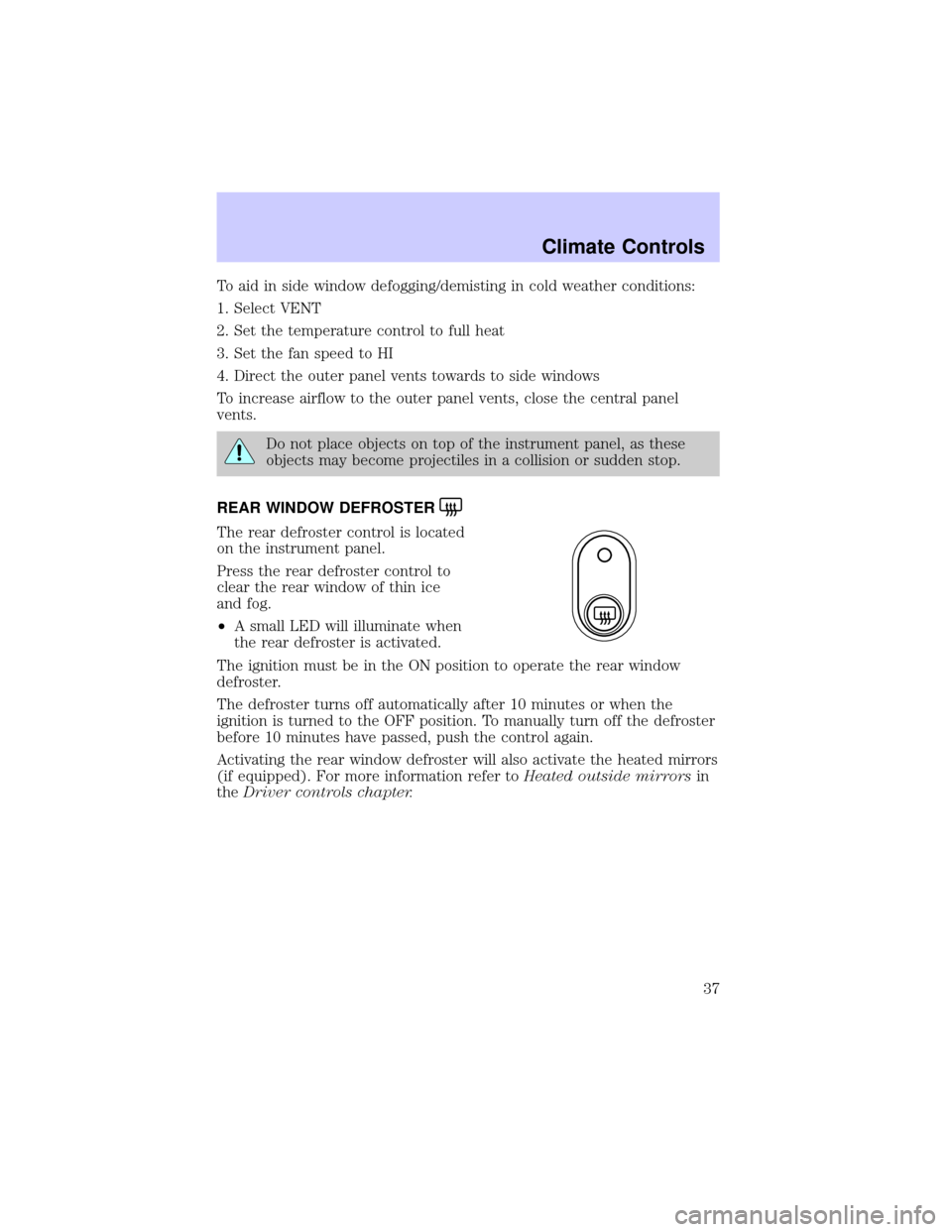
REAR WINDOW DEFROSTER
The rear defroster control is located
on the instrument panel.
Press the rear defroster control to
clear the rear window of thin ice
and fog.
²A small LED will illuminate when
the rear defroster is activated.
The ignition must be in the ON position to operate the rear window
defroster.
The defroster turns off automatically after 10 minutes or when the
ignition is turned to the OFF position. To manually turn off the defroster
before 10 minutes have passed, push the control again.
Activating the rear window defroster will also activate the heated mirrors
(if equipped). For more information refer toHeated outside mirrorsin
theDriver controls chapter.
Climate Controls
37
Page 39 of 232
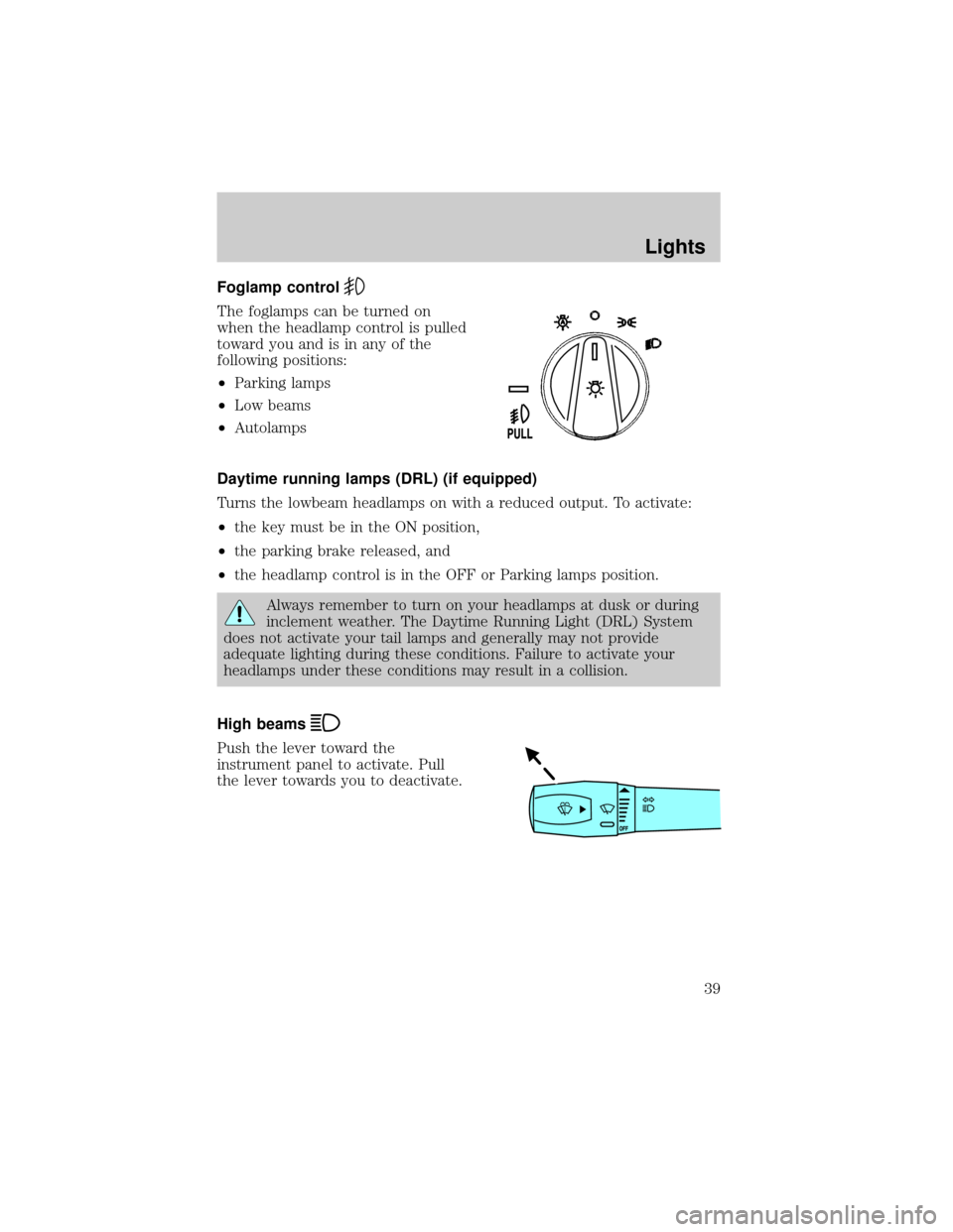
Foglamp control
The foglamps can be turned on
when the headlamp control is pulled
toward you and is in any of the
following positions:
²Parking lamps
²Low beams
²Autolamps
Daytime running lamps (DRL) (if equipped)
Turns the lowbeam headlamps on with a reduced output. To activate:
²the key must be in the ON position,
²the parking brake released, and
²the headlamp control is in the OFF or Parking lamps position.
Always remember to turn on your headlamps at dusk or during
inclement weather. The Daytime Running Light (DRL) System
does not activate your tail lamps and generally may not provide
adequate lighting during these conditions. Failure to activate your
headlamps under these conditions may result in a collision.
High beams
Push the lever toward the
instrument panel to activate. Pull
the lever towards you to deactivate.
Lights
39
Page 40 of 232
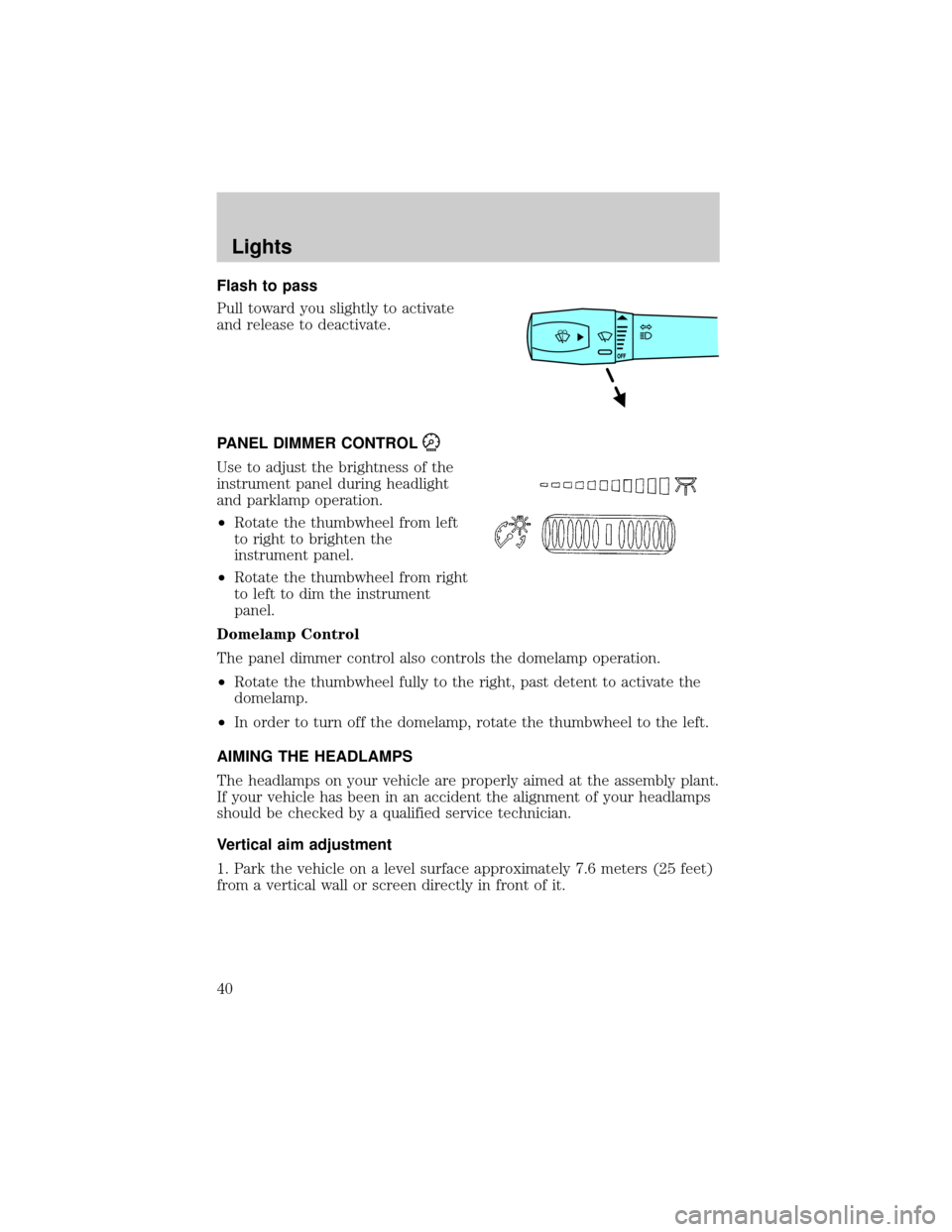
Flash to pass
Pull toward you slightly to activate
and release to deactivate.
PANEL DIMMER CONTROL
Use to adjust the brightness of the
instrument panel during headlight
and parklamp operation.
²Rotate the thumbwheel from left
to right to brighten the
instrument panel.
²Rotate the thumbwheel from right
to left to dim the instrument
panel.
Domelamp Control
The panel dimmer control also controls the domelamp operation.
²Rotate the thumbwheel fully to the right, past detent to activate the
domelamp.
²In order to turn off the domelamp, rotate the thumbwheel to the left.
AIMING THE HEADLAMPS
The headlamps on your vehicle are properly aimed at the assembly plant.
If your vehicle has been in an accident the alignment of your headlamps
should be checked by a qualified service technician.
Vertical aim adjustment
1. Park the vehicle on a level surface approximately 7.6 meters (25 feet)
from a vertical wall or screen directly in front of it.
Lights
40
Page 50 of 232
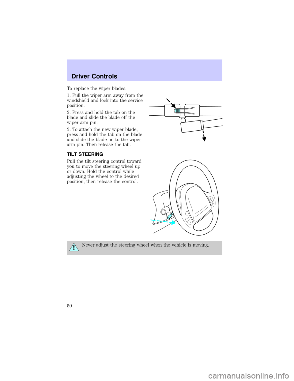
To replace the wiper blades:
1. Pull the wiper arm away from the
windshield and lock into the service
position.
2. Press and hold the tab on the
blade and slide the blade off the
wiper arm pin.
3. To attach the new wiper blade,
press and hold the tab on the blade
and slide the blade on to the wiper
arm pin. Then release the tab.
TILT STEERING
Pull the tilt steering control toward
you to move the steering wheel up
or down. Hold the control while
adjusting the wheel to the desired
position, then release the control.
Never adjust the steering wheel when the vehicle is moving.
Driver Controls
50
Page 63 of 232
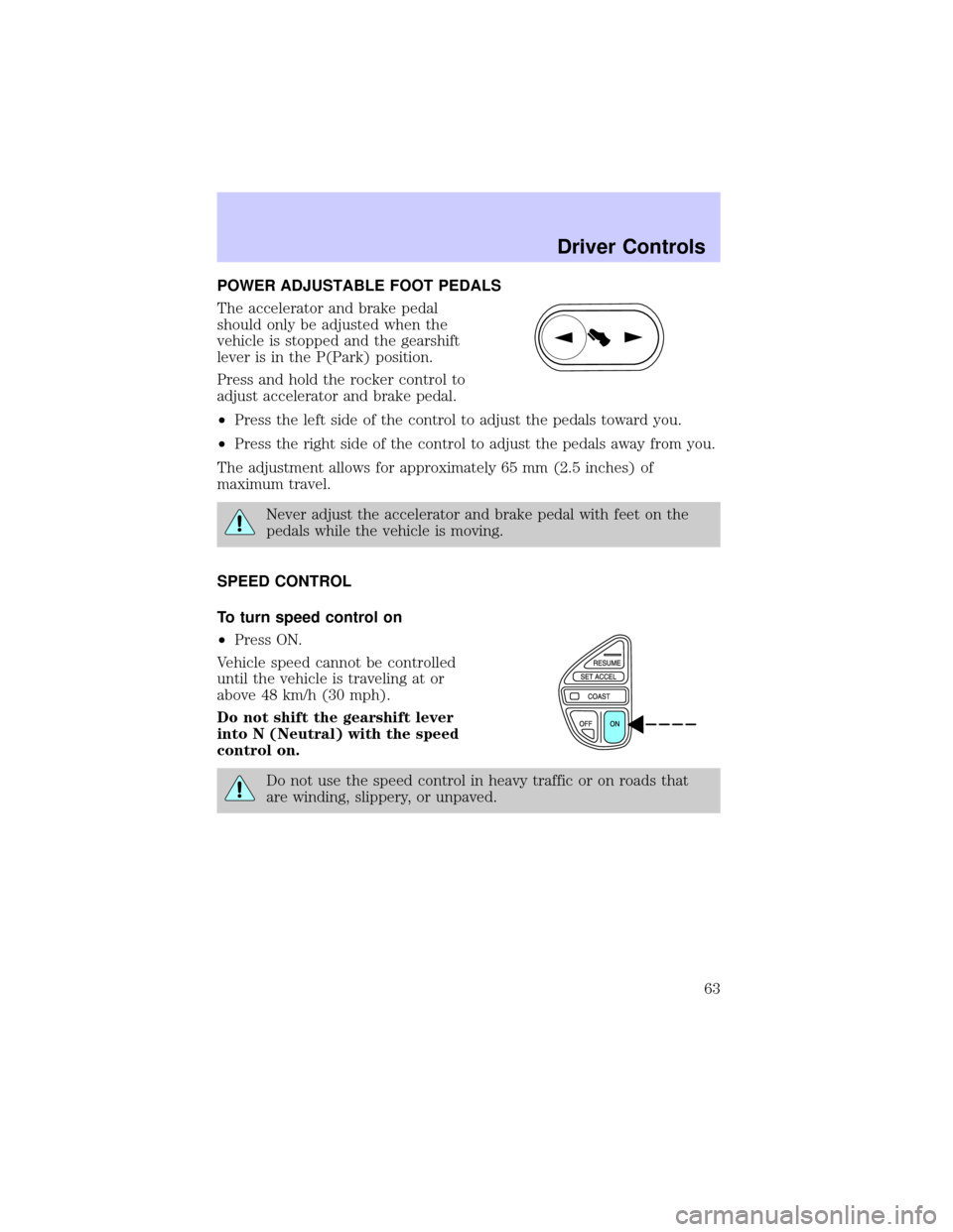
POWER ADJUSTABLE FOOT PEDALS
The accelerator and brake pedal
should only be adjusted when the
vehicle is stopped and the gearshift
lever is in the P(Park) position.
Press and hold the rocker control to
adjust accelerator and brake pedal.
²Press the left side of the control to adjust the pedals toward you.
²Press the right side of the control to adjust the pedals away from you.
The adjustment allows for approximately 65 mm (2.5 inches) of
maximum travel.
Never adjust the accelerator and brake pedal with feet on the
pedals while the vehicle is moving.
SPEED CONTROL
To turn speed control on
²Press ON.
Vehicle speed cannot be controlled
until the vehicle is traveling at or
above 48 km/h (30 mph).
Do not shift the gearshift lever
into N (Neutral) with the speed
control on.
Do not use the speed control in heavy traffic or on roads that
are winding, slippery, or unpaved.
Driver Controls
63