turn signal Mercury Marauder 2003 Owner's Manuals
[x] Cancel search | Manufacturer: MERCURY, Model Year: 2003, Model line: Marauder, Model: Mercury Marauder 2003Pages: 232, PDF Size: 2.29 MB
Page 1 of 232
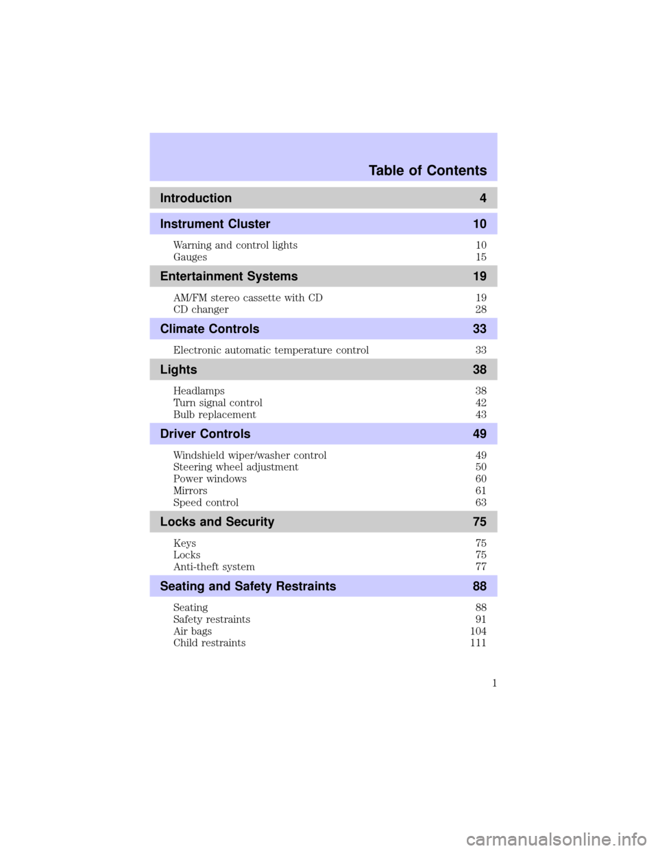
Introduction 4
Instrument Cluster 10
Warning and control lights 10
Gauges 15
Entertainment Systems 19
AM/FM stereo cassette with CD 19
CD changer 28
Climate Controls 33
Electronic automatic temperature control 33
Lights 38
Headlamps 38
Turn signal control 42
Bulb replacement 43
Driver Controls 49
Windshield wiper/washer control 49
Steering wheel adjustment 50
Power windows 60
Mirrors 61
Speed control 63
Locks and Security 75
Keys 75
Locks 75
Anti-theft system 77
Seating and Safety Restraints 88
Seating 88
Safety restraints 91
Air bags 104
Child restraints 111
Table of Contents
1
Page 14 of 232
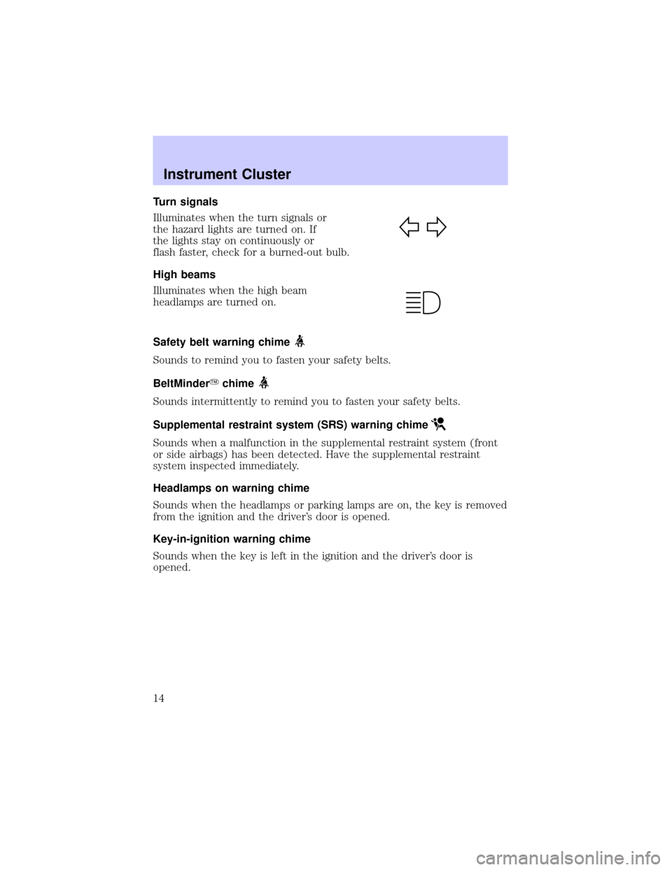
Turn signals
Illuminates when the turn signals or
the hazard lights are turned on. If
the lights stay on continuously or
flash faster, check for a burned-out bulb.
High beams
Illuminates when the high beam
headlamps are turned on.
Safety belt warning chime
Sounds to remind you to fasten your safety belts.
BeltMinderYchime
Sounds intermittently to remind you to fasten your safety belts.
Supplemental restraint system (SRS) warning chime
Sounds when a malfunction in the supplemental restraint system (front
or side airbags) has been detected. Have the supplemental restraint
system inspected immediately.
Headlamps on warning chime
Sounds when the headlamps or parking lamps are on, the key is removed
from the ignition and the driver's door is opened.
Key-in-ignition warning chime
Sounds when the key is left in the ignition and the driver's door is
opened.
Instrument Cluster
14
Page 28 of 232
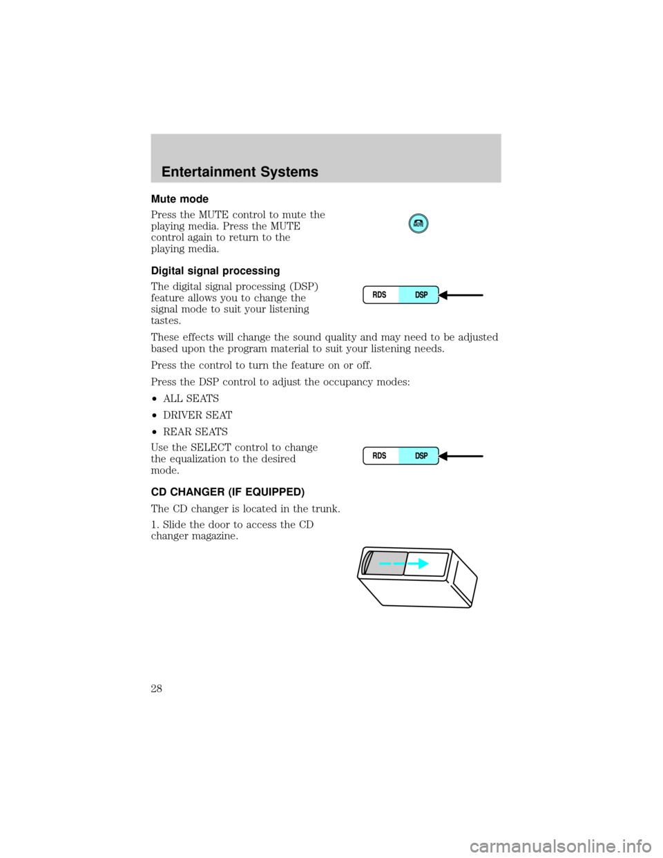
Mute mode
Press the MUTE control to mute the
playing media. Press the MUTE
control again to return to the
playing media.
Digital signal processing
The digital signal processing (DSP)
feature allows you to change the
signal mode to suit your listening
tastes.
These effects will change the sound quality and may need to be adjusted
based upon the program material to suit your listening needs.
Press the control to turn the feature on or off.
Press the DSP control to adjust the occupancy modes:
²ALL SEATS
²DRIVER SEAT
²REAR SEATS
Use the SELECT control to change
the equalization to the desired
mode.
CD CHANGER (IF EQUIPPED)
The CD changer is located in the trunk.
1. Slide the door to access the CD
changer magazine.
Entertainment Systems
28
Page 32 of 232
²Tighten very loose tapes by inserting a finger or pencil into the hole
and turning the hub.
²Remove loose labels before inserting tapes.
²Do not leave tapes in the cassette player for a long time when not
being played.
RADIO FREQUENCY INFORMATION
The Federal Communications Commission (FCC) and the Canadian Radio
and Telecommunications Commission(CRTC) establish the frequencies
AM and FM stations may use for their broadcasts. Allowable frequencies
are:
AM 530, 540±1600, 1610 kHz
FM 87.7, 87.9±107.7, 107.9 MHz
Not all frequencies are used in a given area.
RADIO RECEPTION FACTORS
Three factors can affect radio reception:
²Distance/strength.The further an FM signal travels, the weaker it is.
The listenable range of the average FM station is approximately 40 km
(24 miles). This range can be affected by ªsignal modulation.º Signal
modulation is a process radio stations use to increase their
strength/volume relative to other stations.
²Terrain.Hills, mountains and tall buildings between your vehicle's
antenna and the radio station signal can cause FM reception problems.
Static can be caused on AM stations by power lines, electric fences,
traffic lights and thunderstorms. Moving away from an interfering
structure (out of its ªshadowº) returns your reception to normal.
²Station overload.Weak signals are sometimes captured by stronger
signals when you pass a broadcast tower. A stronger signal may
temporarily overtake a weaker signal and play while the weak station
frequency is displayed.
The audio system automatically switches to single channel reception if it
will improve the reception of a station normally received in stereo.
AUDIO SYSTEM WARRANTIES AND SERVICE
Refer to theWarranty Guidefor audio system warranty information.
If service is necessary, see your dealer or a qualified technician.
Entertainment Systems
32
Page 42 of 232
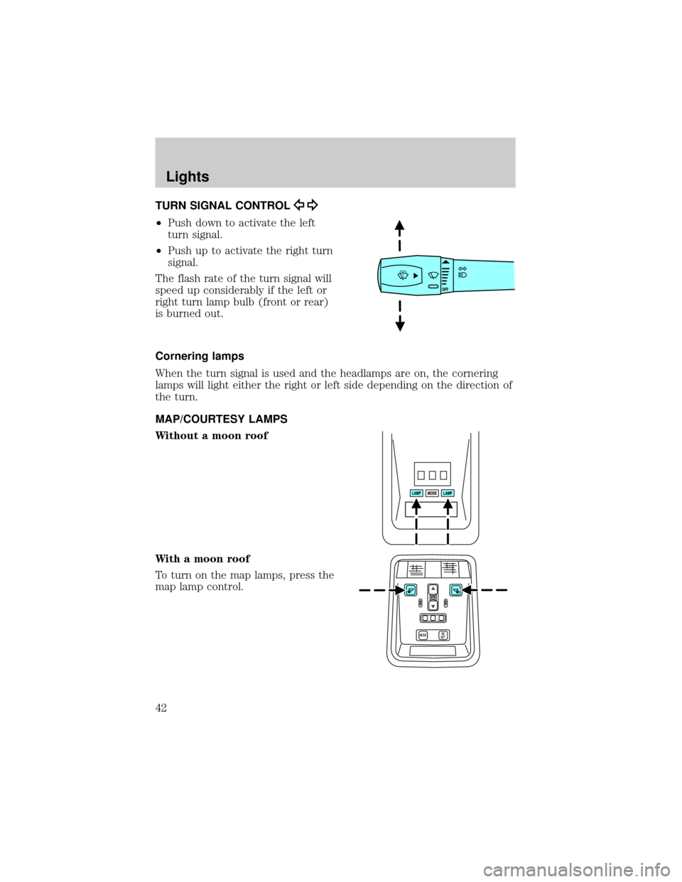
TURN SIGNAL CONTROL
²Push down to activate the left
turn signal.
²Push up to activate the right turn
signal.
The flash rate of the turn signal will
speed up considerably if the left or
right turn lamp bulb (front or rear)
is burned out.
Cornering lamps
When the turn signal is used and the headlamps are on, the cornering
lamps will light either the right or left side depending on the direction of
the turn.
MAP/COURTESY LAMPS
Without a moon roof
With a moon roof
To turn on the map lamps, press the
map lamp control.
Lights
42
Page 45 of 232

The headlamp bulb should not be removed from the headlamp until just
before a replacement bulb is installed. Removing the bulb for an
extended period of time may affect headlamp bulb performance.
Contaminants may enter the headlamp where they can settle on the lens
and reflector. Never turn the headlamps on with the bulb removed.
Replacing front parking lamp/turn signal bulbs
The park/turn lamp bulbs can be replaced with out removing the
headlamp assembly.
1. Make sure headlamp switch is in OFF position, then open the hood.
2. Remove the three pin type retainers and the radiator shield.
3. Remove the headlamp assembly retaining nuts, the side turn signal
lamp retaining nuts and the side turn signal assembly.
4. Remove the bulb from the side turn lamp assembly.
5. Disconnect the electrical connector from the bulb and replace the
bulb.
Note: The parking lamp/turn signal bulbs should not be removed from
the lamp until just before a replacement bulb is installed. Removing the
bulb for an extended period of time may affect headlamp bulb
performance. Contaminants may enter the headlamp where they can
settle on the lens and reflector. Never turn the lamps on with the bulb
removed.
6. To install, reverse the order of the removal procedure.
Replacing tail lamp/brake/turn lamp bulbs
The tail lamp, the brake lamp and the turn signal lamp bulbs are located
in the tail lamp assembly. Follow the same steps to replace either bulb.
Lights
45
Page 68 of 232
²To close from the vent position, press and hold the rear portion of the
control.
Do not let children play with the moon roof. They may seriously
hurt themselves.
HOMELINKTUNIVERSAL TRANSCEIVER
The HomeLinktUniversal Transceiver, located on the driver's visor,
provides a convenient way to replace up to three hand-held transmitters
with a single built-in device. This feature will learn the radio frequency
codes of most current transmitters to operate garage doors, entry gate
operators, security systems, entry door locks, and home or office lighting.
When programming your HomeLinktUniversal Transceiver to a
garage door or gate, be sure that people and objects are out of
the way to prevent potential harm or damage.
Do not use the HomeLinktUniversal Transceiver with any garage door
opener that lacks safety stop and reverse features as required by U.S.
federal safety standards (this includes any garage door opener model
manufactured before April 1, 1982). A garage door which cannot detect
an object, signaling the door to stop and reverse, does not meet current
U.S. federal safety standards. For more information, contact HomeLinkt
at:www.homelink.comor1±800±355±3515.
Retain the original transmitter for use in other vehicles as well as for
future programming procedures (i.e. new HomeLinktequipped vehicle
purchase). It is also suggested that upon the sale of the vehicle, the
programmed HomelinktUniversal Transceiver buttons be erased for
security purposes, refer toProgrammingin this section.
Programming
Do not program the HomeLinktUniversal Transceiver with the
vehicle parked in the garage.
Note:Some vehicles may require the ignition switch to be turned to the
second (or ªACCº) position for programming and/or operation of the
HomeLinkt. It is also recommended that a new battery be placed in the
hand-held transmitter of the device being programmed to HomeLinktfor
quicker training and accurate transmission of the radio-frequency signal.
Driver Controls
68
Page 69 of 232
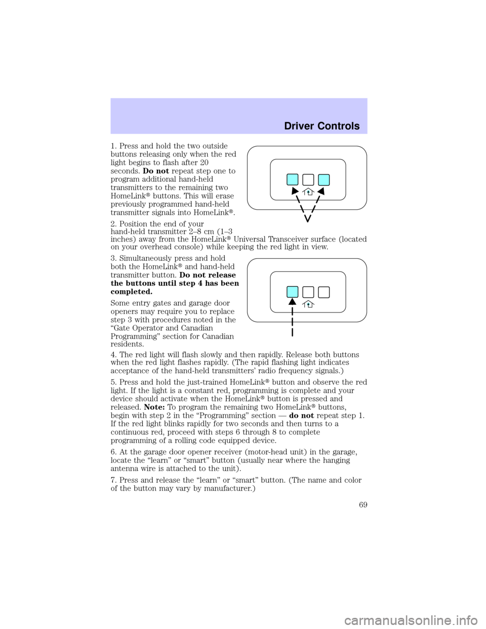
1. Press and hold the two outside
buttons releasing only when the red
light begins to flash after 20
seconds.Do notrepeat step one to
program additional hand-held
transmitters to the remaining two
HomeLinktbuttons. This will erase
previously programmed hand-held
transmitter signals into HomeLinkt.
2. Position the end of your
hand-held transmitter 2±8 cm (1±3
inches) away from the HomeLinktUniversal Transceiver surface (located
on your overhead console) while keeping the red light in view.
3. Simultaneously press and hold
both the HomeLinktand hand-held
transmitter button.Do not release
the buttons until step 4 has been
completed.
Some entry gates and garage door
openers may require you to replace
step 3 with procedures noted in the
ªGate Operator and Canadian
Programmingº section for Canadian
residents.
4. The red light will flash slowly and then rapidly. Release both buttons
when the red light flashes rapidly. (The rapid flashing light indicates
acceptance of the hand-held transmitters' radio frequency signals.)
5. Press and hold the just-trained HomeLinktbutton and observe the red
light. If the light is a constant red, programming is complete and your
device should activate when the HomeLinktbutton is pressed and
released.Note:To program the remaining two HomeLinktbuttons,
begin with step 2 in the ªProgrammingº section Ðdo notrepeat step 1.
If the red light blinks rapidly for two seconds and then turns to a
continuous red, proceed with steps 6 through 8 to complete
programming of a rolling code equipped device.
6. At the garage door opener receiver (motor-head unit) in the garage,
locate the ªlearnº or ªsmartº button (usually near where the hanging
antenna wire is attached to the unit).
7. Press and release the ªlearnº or ªsmartº button. (The name and color
of the button may vary by manufacturer.)
Driver Controls
69
Page 224 of 232

H
Hazard flashers .........................143
Head restraints ...........................88
Headlamps ...................................38
aiming ........................................40
autolamp system .......................38
bulb specifications ....................43
daytime running lights .............39
flash to pass ..............................40
high beam ...........................14, 39
replacing bulbs .........................44
turning on and off ....................38
warning chime ..........................14
Heating
heating and air conditioning
system .......................................33
HomeLink universal
transceiver (see Garage
door opener) ...................56, 68, 70
Hood ..........................................180
I
Ignition ...............................122, 214
Infant seats
(see Safety seats) .....................114
Inspection/maintenance (I/M)
testing ........................................202
Instrument panel
cleaning ...................................176
cluster ........................................10
lighting up panel and
interior .......................................40
J
Jack ............................................151
positioning ...............................151
storage .....................................151Jump-starting your vehicle ......156
K
Keyless entry system .................82
autolock .....................................81
keypad .......................................82
programming entry code .........83
Keys .......................................84±86
key in ignition chime ...............14
positions of the ignition .........122
L
Lamps
autolamp system .......................38
bulb replacement
specifications chart ..................43
cargo lamps ...............................40
daytime running light ...............39
fog lamps ...................................39
headlamps .................................38
headlamps, flash to pass ..........40
instrument panel, dimming .....40
interior lamps .....................42±43
replacing bulbs ....... 43±45, 47±48
Lane change indicator
(see Turn signal) ........................42
Lights, warning and indicator ....10
air bag ........................................12
air suspension ...........................13
anti-lock brakes (ABS) ....12, 127
brake ..........................................11
charging system ........................12
check engine .............................10
fuel cap light .............................11
high beam .................................14
low coolant ................................13
low fuel ......................................13
overdrive off ..............................13
safety belt .................................12
Index
224
Page 225 of 232

traction control active ..............13
turn signal indicator .................14
Limited-slip axle .......................135
Load limits .................................136
GAWR ......................................136
GVWR ......................................136
trailer towing ..........................136
Locks
autolock .....................................81
childproof ..................................76
doors ..........................................75
Lubricant specifications ...212, 214
Lumbar support, seats ...............88
M
Mirrors .........................................51
automatic dimming rearview
mirror ........................................62
fold away ...................................62
heated ........................................62
side view mirrors (power) .......61
Moon roof ....................................67
Motorcraft parts ................198, 211
O
Octane rating ............................197
Odometer .....................................17
Oil (see Engine oil) ..................182
Overdrive .............................71, 133
P
Panic alarm feature, remote
entry system ................................79
Parking brake ............................127
Parts (see Motorcraft parts) ....211Passenger Occupant
Classification Sensor ...................92
Pedals (see Power adjustable
foot pedals) .................................63
Power adjustable foot pedals .....63
Power distribution box
(see Fuses) ...............................148
Power door locks ..................75, 81
Power mirrors .............................61
Power point .................................59
Power steering ..................129±130
fluid, checking and adding ....203
fluid, refill capacity ................211
fluid, specifications .................212
Power Windows ...........................60
R
Radio ............................................19
Radio reception ...........................32
Rear window defroster ...............37
Relays ................................144, 151
Remote entry system ...........77, 79
illuminated entry ......................81
locking/unlocking doors .....75, 78
opening the trunk .....................79
panic alarm ...............................79
replacement/additional
transmitters ...............................80
replacing the batteries .............79
Roadside assistance ..................142
S
Safety belts (see Safety
restraints) ............14, 91, 94, 96±98
Safety defects, reporting ..........172
Index
225