instrument cluster Mercury Marauder 2004 s User Guide
[x] Cancel search | Manufacturer: MERCURY, Model Year: 2004, Model line: Marauder, Model: Mercury Marauder 2004Pages: 224, PDF Size: 3.21 MB
Page 93 of 224
If the air bag has deployed,the air bag will not function
again and must be replaced immediately.If the air bag is not
replaced, the unrepaired area will increase the risk of injury in a
collision.
If the safety belt pretensioners deploy in an accident, they will
not function again ( belt will not extract or retract) and must be
replaced immediately. Failure to replace the retractor assemblies will
increase the risk of injury.
Determining if the system is operational
The SRS uses a readiness light in the instrument cluster or a tone to
indicate the condition of the system. Refer toAir bag readinesssection
in theInstrument Clusterchapter. Routine maintenance of the air bag is
not required.
A difficulty with the system is indicated by one or more of the following:
²The readiness light will either
flash or stay lit.
²The readiness light will not
illuminate immediately after
ignition is turned on.
²A series of five beeps will be heard. The tone pattern will repeat
periodically until the problem and/or light are repaired.
If any of these things happen, even intermittently, have the SRS serviced
at your dealership or by a qualified technician immediately. Unless
serviced, the system may not function properly in the event of a
collision.
Side air bag system
Do not place objects or mount equipment on or near the air bag
cover on the side of the seatbacks of the front seats or in front
seat areas that may come into contact with a deploying air bag. Failure
to follow these instructions may increase the risk of personal injury in
the event of a collision.
2004 Marauder(mdr)
Owners Guide (post-2002-fmt)
USA English(fus)
Seating and Safety Restraints
93
Page 95 of 224
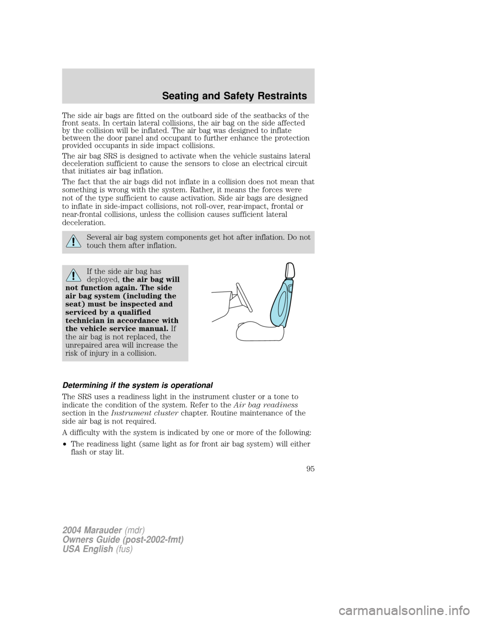
The side air bags are fitted on the outboard side of the seatbacks of the
front seats. In certain lateral collisions, the air bag on the side affected
by the collision will be inflated. The air bag was designed to inflate
between the door panel and occupant to further enhance the protection
provided occupants in side impact collisions.
The air bag SRS is designed to activate when the vehicle sustains lateral
deceleration sufficient to cause the sensors to close an electrical circuit
that initiates air bag inflation.
The fact that the air bags did not inflate in a collision does not mean that
something is wrong with the system. Rather, it means the forces were
not of the type sufficient to cause activation. Side air bags are designed
to inflate in side-impact collisions, not roll-over, rear-impact, frontal or
near-frontal collisions, unless the collision causes sufficient lateral
deceleration.
Several air bag system components get hot after inflation. Do not
touch them after inflation.
If the side air bag has
deployed,the air bag will
not function again. The side
air bag system (including the
seat) must be inspected and
serviced by a qualified
technician in accordance with
the vehicle service manual.If
the air bag is not replaced, the
unrepaired area will increase the
risk of injury in a collision.
Determining if the system is operational
The SRS uses a readiness light in the instrument cluster or a tone to
indicate the condition of the system. Refer to theAir bag readiness
section in theInstrument clusterchapter. Routine maintenance of the
side air bag is not required.
A difficulty with the system is indicated by one or more of the following:
²The readiness light (same light as for front air bag system) will either
flash or stay lit.
2004 Marauder(mdr)
Owners Guide (post-2002-fmt)
USA English(fus)
Seating and Safety Restraints
95
Page 112 of 224
BRAKES
Your service brakes are self-adjusting. Refer to the scheduled
maintenance guide for scheduled maintenance.
Occasional brake noise is normal and often does not indicate a
performance concern with the vehicle's brake system. In normal
operation, automotive brake systems may emit occasional or intermittent
squeal or groan noises when the brakes are applied. Such noises are
usually heard during the first few brake applications in the morning;
however, they may be heard at any time while braking and can be
aggravated by environmental conditions such as cold, heat, moisture,
road dust, salt or mud. If a ªmetal-to-metal,º ªcontinuous grindingº or
ªcontinuous squealº sound is present while braking, the brake linings
may be worn-out and should be inspected by a qualified service
technician.
Refer toBrake system warning
lightin theInstrument Cluster
chapter for information on the brake
system warning light.
If you are driving down a long or steep hill, shift to a lower gear.
Do not apply your brakes continuously, as they may overheat
and become less effective.
Anti-lock brake system (ABS)
This vehicle is equipped with an anti-lock braking system (ABS). A noise
from the hydraulic pump motor and pulsation in the pedal may be
observed during ABS braking events. Pedal pulsation coupled with noise
while braking under panic conditions or on loose gravel, bumps, wet or
snowy roads is normal and indicates proper functioning of the vehicle's
anti-lock brake system. If the vehicle has continuous vibration or shudder
in the steering wheel while braking, the vehicle should be inspected by a
qualified service technician.
!
BRAKE
2004 Marauder(mdr)
Owners Guide (post-2002-fmt)
USA English(fus)
Driving
112
Page 113 of 224
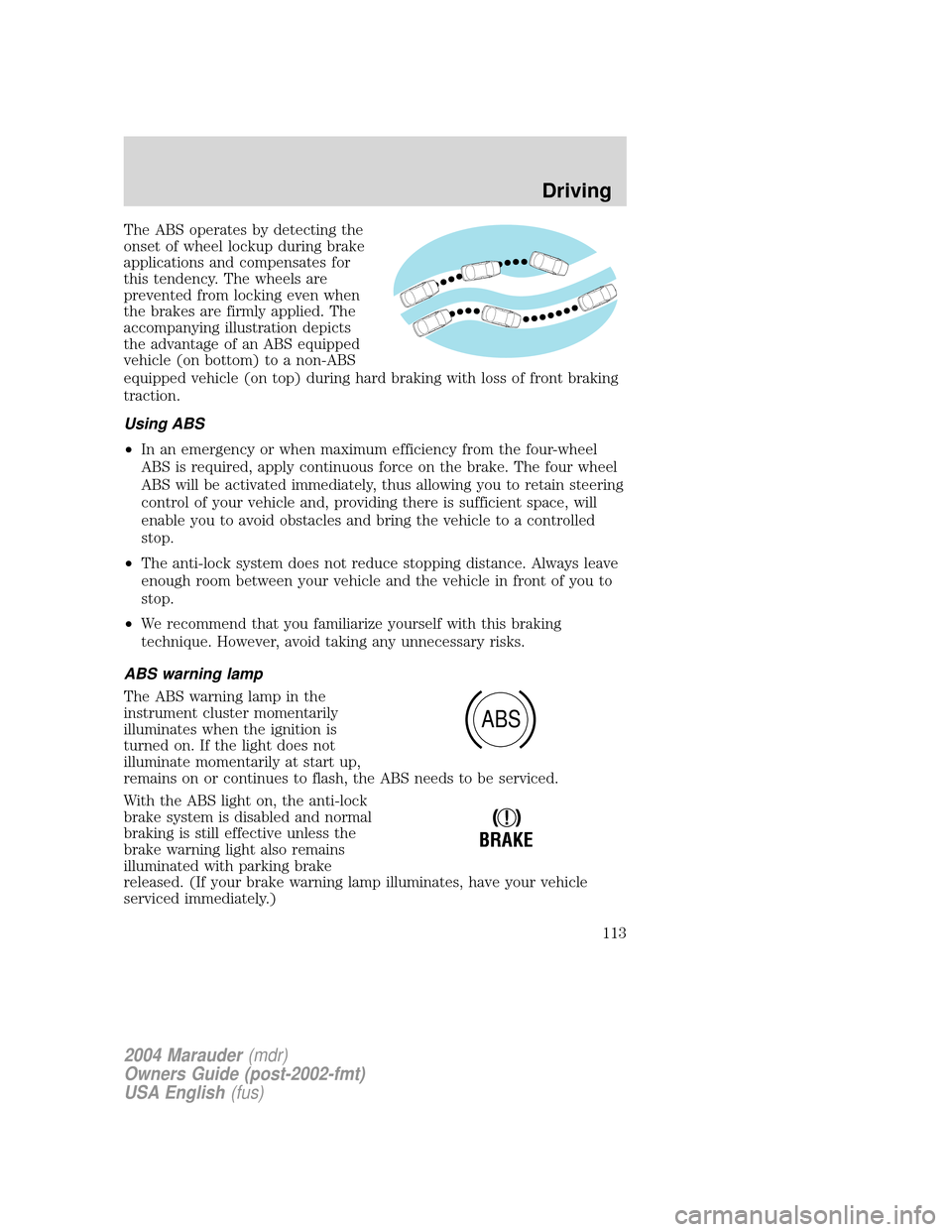
The ABS operates by detecting the
onset of wheel lockup during brake
applications and compensates for
this tendency. The wheels are
prevented from locking even when
the brakes are firmly applied. The
accompanying illustration depicts
the advantage of an ABS equipped
vehicle (on bottom) to a non-ABS
equipped vehicle (on top) during hard braking with loss of front braking
traction.
Using ABS
²In an emergency or when maximum efficiency from the four-wheel
ABS is required, apply continuous force on the brake. The four wheel
ABS will be activated immediately, thus allowing you to retain steering
control of your vehicle and, providing there is sufficient space, will
enable you to avoid obstacles and bring the vehicle to a controlled
stop.
²The anti-lock system does not reduce stopping distance. Always leave
enough room between your vehicle and the vehicle in front of you to
stop.
²We recommend that you familiarize yourself with this braking
technique. However, avoid taking any unnecessary risks.
ABS warning lamp
The ABS warning lamp in the
instrument cluster momentarily
illuminates when the ignition is
turned on. If the light does not
illuminate momentarily at start up,
remains on or continues to flash, the ABS needs to be serviced.
With the ABS light on, the anti-lock
brake system is disabled and normal
braking is still effective unless the
brake warning light also remains
illuminated with parking brake
released. (If your brake warning lamp illuminates, have your vehicle
serviced immediately.)
ABS
!
BRAKE
2004 Marauder(mdr)
Owners Guide (post-2002-fmt)
USA English(fus)
Driving
113
Page 114 of 224
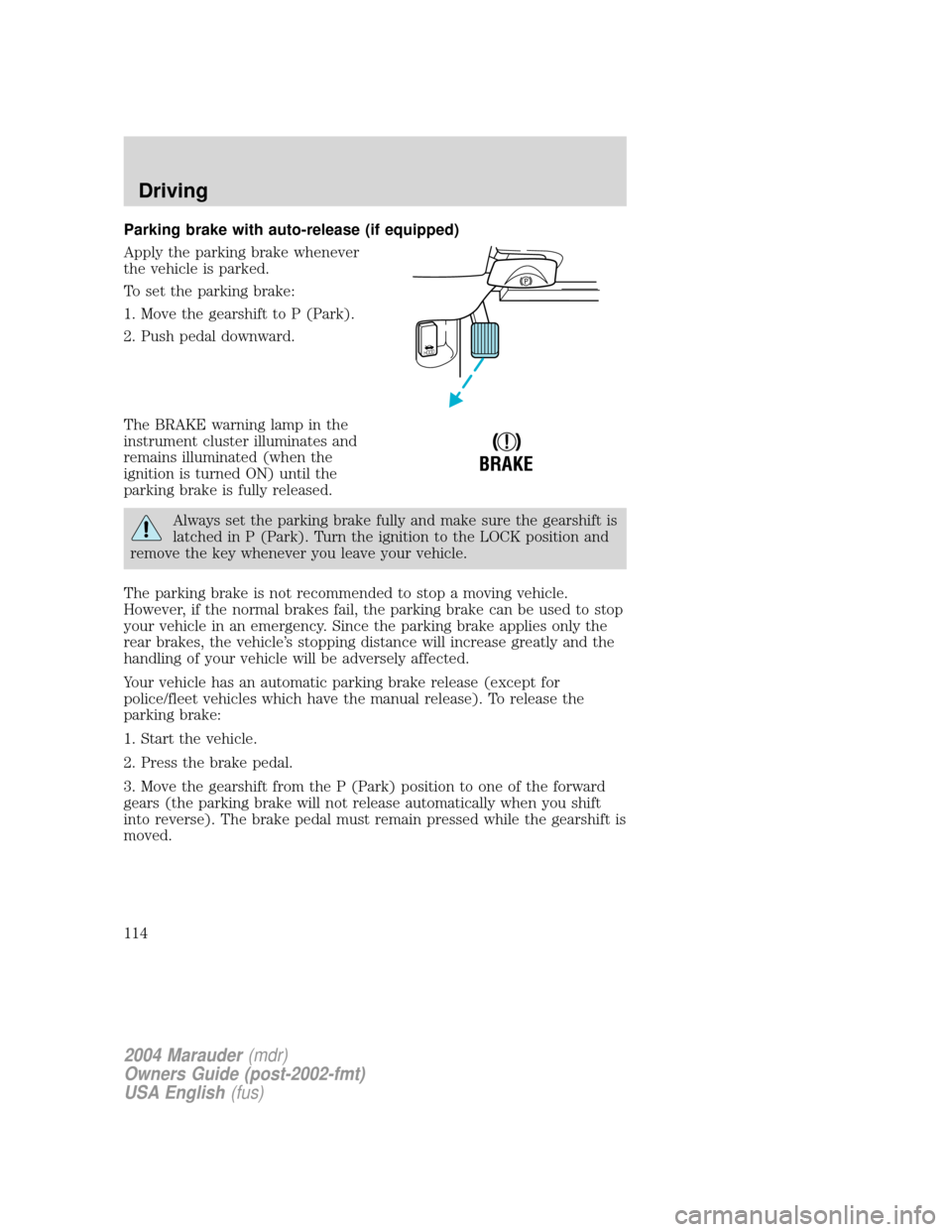
Parking brake with auto-release (if equipped)
Apply the parking brake whenever
the vehicle is parked.
To set the parking brake:
1. Move the gearshift to P (Park).
2. Push pedal downward.
The BRAKE warning lamp in the
instrument cluster illuminates and
remains illuminated (when the
ignition is turned ON) until the
parking brake is fully released.
Always set the parking brake fully and make sure the gearshift is
latched in P (Park). Turn the ignition to the LOCK position and
remove the key whenever you leave your vehicle.
The parking brake is not recommended to stop a moving vehicle.
However, if the normal brakes fail, the parking brake can be used to stop
your vehicle in an emergency. Since the parking brake applies only the
rear brakes, the vehicle's stopping distance will increase greatly and the
handling of your vehicle will be adversely affected.
Your vehicle has an automatic parking brake release (except for
police/fleet vehicles which have the manual release). To release the
parking brake:
1. Start the vehicle.
2. Press the brake pedal.
3. Move the gearshift from the P (Park) position to one of the forward
gears (the parking brake will not release automatically when you shift
into reverse). The brake pedal must remain pressed while the gearshift is
moved.
HOOD
!
BRAKE
2004 Marauder(mdr)
Owners Guide (post-2002-fmt)
USA English(fus)
Driving
114
Page 133 of 224
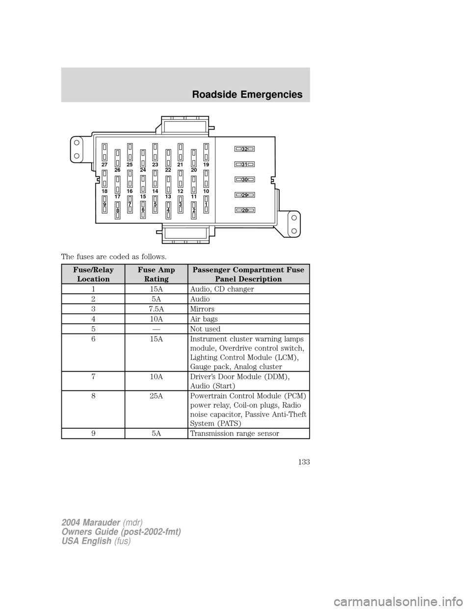
The fuses are coded as follows.
Fuse/Relay
LocationFuse Amp
RatingPassenger Compartment Fuse
Panel Description
1 15A Audio, CD changer
2 5A Audio
3 7.5A Mirrors
4 10A Air bags
5 Ð Not used
6 15A Instrument cluster warning lamps
module, Overdrive control switch,
Lighting Control Module (LCM),
Gauge pack, Analog cluster
7 10A Driver's Door Module (DDM),
Audio (Start)
8 25A Powertrain Control Module (PCM)
power relay, Coil-on plugs, Radio
noise capacitor, Passive Anti-Theft
System (PATS)
9 5A Transmission range sensor
27 25
26 2423 21
2219
20
18 16
17 1514 12
131030
32
31
28
29
11
97
8653
41
2
2004 Marauder(mdr)
Owners Guide (post-2002-fmt)
USA English(fus)
Roadside Emergencies
133
Page 134 of 224
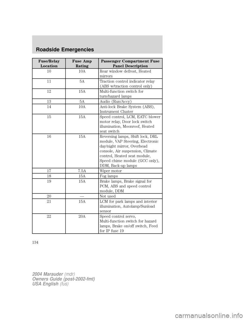
Fuse/Relay
LocationFuse Amp
RatingPassenger Compartment Fuse
Panel Description
10 10A Rear window defrost, Heated
mirrors
11 5A Traction control indicator relay
(ABS w/traction control only)
12 15A Multi-function switch for
turn/hazard lamps
13 5A Audio (Run/Accy)
14 10A Anti-lock Brake System (ABS),
Instrument Cluster
15 15A Speed control, LCM, EATC blower
motor relay, Door lock switch
illumination, Moonroof, Heated
seat switch
16 15A Reversing lamps, Shift lock, DRL
module, VAP Steering, Electronic
day/night mirror, Overhead
console, Air suspension, Climate
control, Heated seat module,
Speed chime module (GCC only),
DDM, Back-up lamps
17 7.5A Wiper motor
18 15A Fog lamps
19 15A Brake lamps, Brake signal for
PCM, ABS and speed control
module, DDM
20 Ð Not used
21 15A LCM for park lamps and interior
illumination, Autolamp/Sunload
sensor
22 20A Speed control servo,
Multi-function switch for hazard
lamps, Brake on/off switch, Feed
for IP fuse 19
2004 Marauder(mdr)
Owners Guide (post-2002-fmt)
USA English(fus)
Roadside Emergencies
134
Page 135 of 224
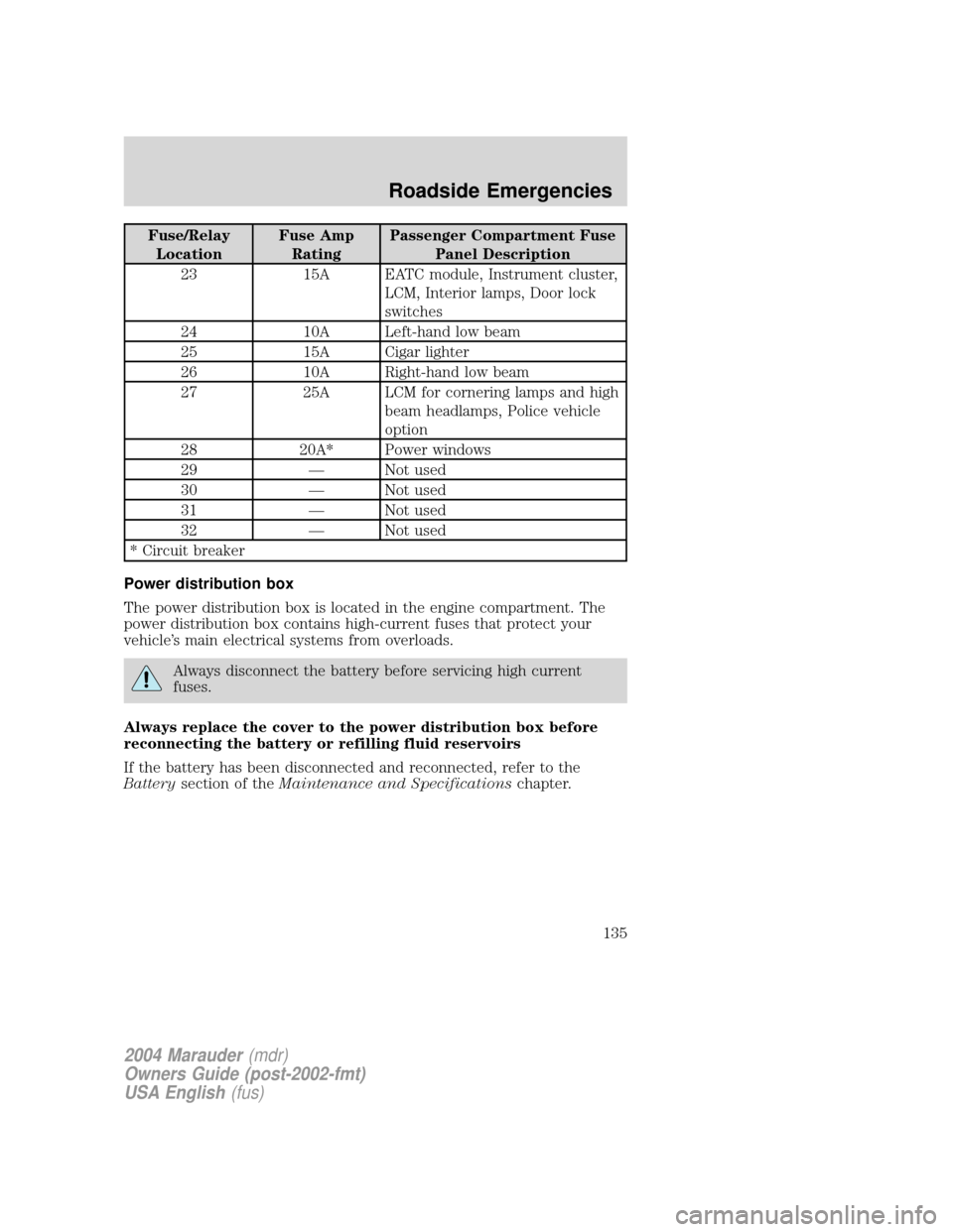
Fuse/Relay
LocationFuse Amp
RatingPassenger Compartment Fuse
Panel Description
23 15A EATC module, Instrument cluster,
LCM, Interior lamps, Door lock
switches
24 10A Left-hand low beam
25 15A Cigar lighter
26 10A Right-hand low beam
27 25A LCM for cornering lamps and high
beam headlamps, Police vehicle
option
28 20A* Power windows
29 Ð Not used
30 Ð Not used
31 Ð Not used
32 Ð Not used
* Circuit breaker
Power distribution box
The power distribution box is located in the engine compartment. The
power distribution box contains high-current fuses that protect your
vehicle's main electrical systems from overloads.
Always disconnect the battery before servicing high current
fuses.
Always replace the cover to the power distribution box before
reconnecting the battery or refilling fluid reservoirs
If the battery has been disconnected and reconnected, refer to the
Batterysection of theMaintenance and Specificationschapter.
2004 Marauder(mdr)
Owners Guide (post-2002-fmt)
USA English(fus)
Roadside Emergencies
135
Page 137 of 224
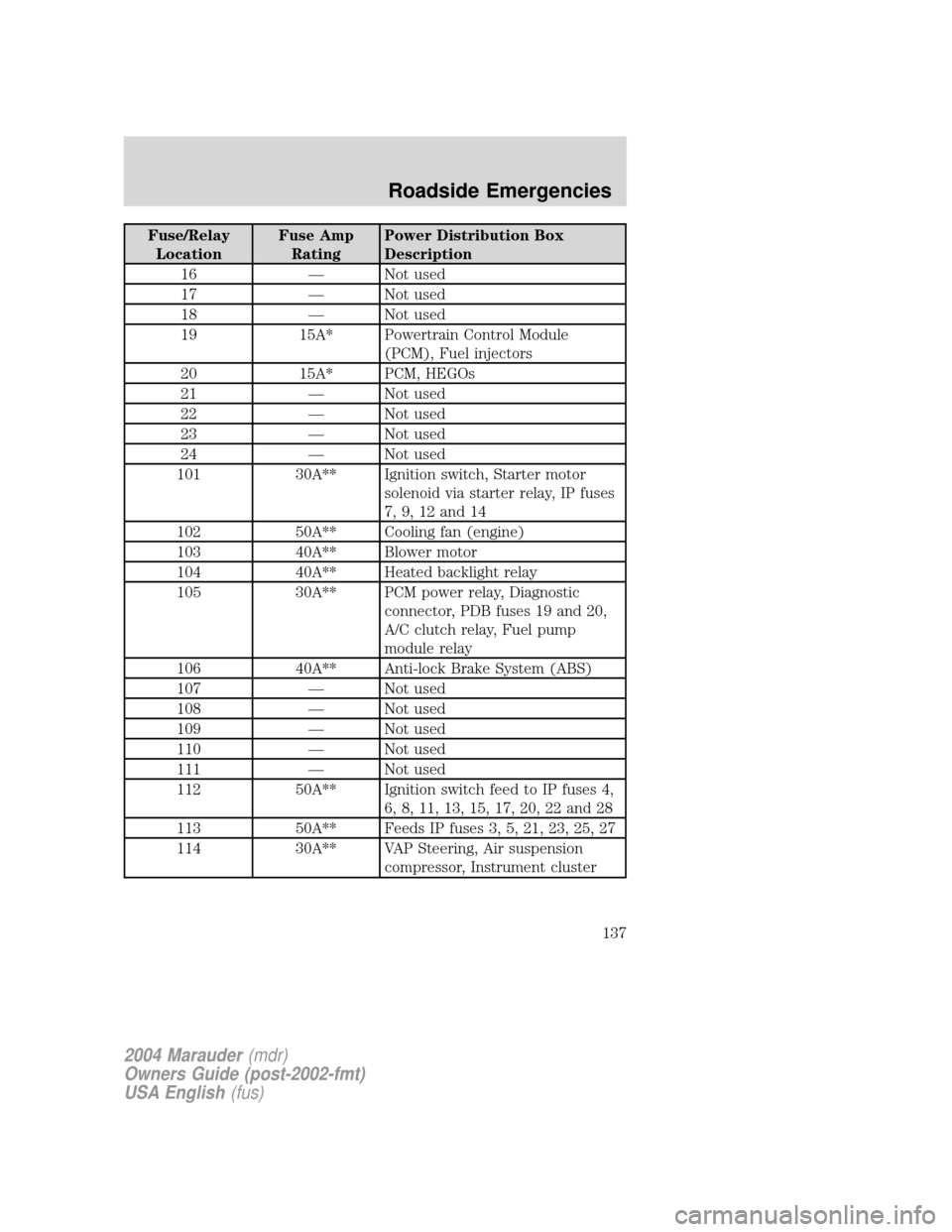
Fuse/Relay
LocationFuse Amp
RatingPower Distribution Box
Description
16 Ð Not used
17 Ð Not used
18 Ð Not used
19 15A* Powertrain Control Module
(PCM), Fuel injectors
20 15A* PCM, HEGOs
21 Ð Not used
22 Ð Not used
23 Ð Not used
24 Ð Not used
101 30A** Ignition switch, Starter motor
solenoid via starter relay, IP fuses
7, 9, 12 and 14
102 50A** Cooling fan (engine)
103 40A** Blower motor
104 40A** Heated backlight relay
105 30A** PCM power relay, Diagnostic
connector, PDB fuses 19 and 20,
A/C clutch relay, Fuel pump
module relay
106 40A** Anti-lock Brake System (ABS)
107 Ð Not used
108 Ð Not used
109 Ð Not used
110 Ð Not used
111 Ð Not used
112 50A** Ignition switch feed to IP fuses 4,
6, 8, 11, 13, 15, 17, 20, 22 and 28
113 50A** Feeds IP fuses 3, 5, 21, 23, 25, 27
114 30A** VAP Steering, Air suspension
compressor, Instrument cluster
2004 Marauder(mdr)
Owners Guide (post-2002-fmt)
USA English(fus)
Roadside Emergencies
137
Page 163 of 224
Do not use sharp objects, such as a razor blade, to clean the
inside of the rear window or to remove decals, as it may cause
damage to the rear window defroster's heated grid lines.
INSTRUMENT PANEL AND CLUSTER LENS
Clean the instrument panel with a damp cloth, then dry with a dry cloth.
²Avoid cleaners or polish that increase the gloss of the upper portion of
the instrument panel. The dull finish in this area helps protect the
driver from undesirable windshield reflection.
Do not use chemical solvents or strong detergents when cleaning
the steering wheel or instrument panel to avoid contamination of
the air bag system.
²Be certain to wash or wipe your hands clean if you have been in
contact with certain products such as insect repellent and suntan
lotion in order to avoid possible damage to the interior painted
surfaces.
INTERIOR TRIM
²Clean the interior trim areas with a damp cloth, then dry by wiping
with a dry, soft, clean cloth.
²Do not use household or glass cleaners as these may damage the
finish.
INTERIOR
For fabric, carpets, cloth seats, safety belts and seats equipped with side
air bags:
²Remove dust and loose dirt with a vacuum cleaner.
²Remove light stains and soil with Motorcraft Extra Strength
Upholstery Cleaner (ZC-41).
²If grease or tar is present on the material, spot-clean the area first
with Motorcraft Spot and Stain Remover (ZC-14).
²Never saturate the seat covers with cleaning solution.
²Do not use household cleaning products or glass cleaners, which can
stain and discolor the fabric and affect the flame retardant abilities of
the seat materials.
2004 Marauder(mdr)
Owners Guide (post-2002-fmt)
USA English(fus)
Cleaning
163