Mercury Milan 2011 Owner's Manuals
Manufacturer: MERCURY, Model Year: 2011, Model line: Milan, Model: Mercury Milan 2011Pages: 354, PDF Size: 2.55 MB
Page 191 of 354

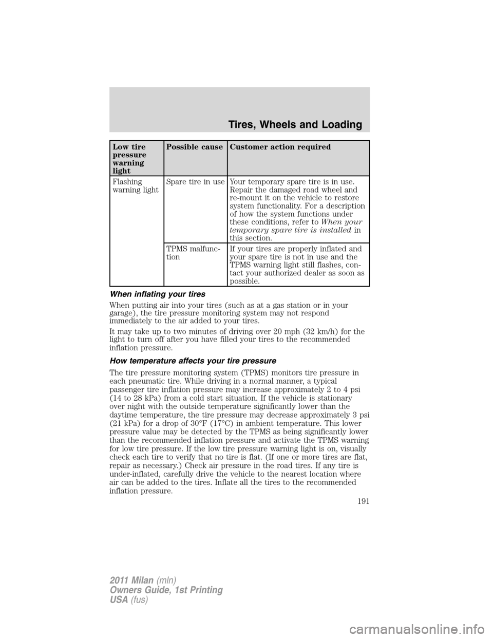
Low tire
pressure
warning
lightPossible cause Customer action required
Flashing
warning lightSpare tire in use Your temporary spare tire is in use.
Repair the damaged road wheel and
re-mount it on the vehicle to restore
system functionality. For a description
of how the system functions under
these conditions, refer toWhen your
temporary spare tire is installedin
this section.
TPMS malfunc-
tionIf your tires are properly inflated and
your spare tire is not in use and the
TPMS warning light still flashes, con-
tact your authorized dealer as soon as
possible.
When inflating your tires
When putting air into your tires (such as at a gas station or in your
garage), the tire pressure monitoring system may not respond
immediately to the air added to your tires.
It may take up to two minutes of driving over 20 mph (32 km/h) for the
light to turn off after you have filled your tires to the recommended
inflation pressure.
How temperature affects your tire pressure
The tire pressure monitoring system (TPMS) monitors tire pressure in
each pneumatic tire. While driving in a normal manner, a typical
passenger tire inflation pressure may increase approximately 2 to 4 psi
(14 to 28 kPa) from a cold start situation. If the vehicle is stationary
over night with the outside temperature significantly lower than the
daytime temperature, the tire pressure may decrease approximately 3 psi
(21 kPa) for a drop of 30°F (17°C) in ambient temperature. This lower
pressure value may be detected by the TPMS as being significantly lower
than the recommended inflation pressure and activate the TPMS warning
for low tire pressure. If the low tire pressure warning light is on, visually
check each tire to verify that no tire is flat. (If one or more tires are flat,
repair as necessary.) Check air pressure in the road tires. If any tire is
under-inflated, carefully drive the vehicle to the nearest location where
air can be added to the tires. Inflate all the tires to the recommended
inflation pressure.
Tires, Wheels and Loading
191
2011 Milan(mln)
Owners Guide, 1st Printing
USA(fus)
Page 192 of 354

SNOW TIRES AND CHAINS
WARNING:Snow tires must be the same size, load index, speed
rating as those originally provided by Ford. Use of any tire or
wheel not recommended by Ford can affect the safety and
performance of your vehicle, which could result in an increased risk of
loss of vehicle control, vehicle rollover, personal injury and death.
Additionally, the use of non-recommended tires and wheels could
cause steering, suspension, axle or transfer case/power transfer unit
failure.
The tires on your vehicle have all weather treads to provide traction in
rain and snow. However, in some climates, you may need to use snow
tires and chains. If you need to use chains, it is recommended that steel
wheels (of the same size and specifications) be used, as chains may chip
aluminum wheels.
Note:The suspension insulation and bumpers will help prevent vehicle
damage. Do not remove these components from your vehicle when using
snow tires and chains.
Follow these guidelines when using snow tires and chains:
•If possible, avoid fully loading your vehicle.
•Use only SAE Class S cables or equivalent on the front axle for
P205/60R16 equipped vehicles. SAE Class S chains or other
conventional link chains may cause damage to the vehicles wheel
house and/or body.
•Do not install tire chains, cables, or optional traction devices on the
rear tires. This could cause damage to the vehicle’s wheel house or
body.
•Do not use tire chains, cables, or optional traction devices with
optional P225/50R17 or P225/45R18 tires.
•Install cable chains securely, verifying that the cables do not touch any
wiring, brake lines or fuel lines.
•Do not exceed 30 mph (48 km/h) with tire cables on your vehicle.
•Drive cautiously. If you hear the cables rub or bang against your
vehicle, stop and retighten the cables. If this does not work, remove
the cables to prevent damage to your vehicle.
•Remove the tire cables when they are no longer needed. Do not use
tire cables on dry roads.
Tires, Wheels and Loading
192
2011 Milan(mln)
Owners Guide, 1st Printing
USA(fus)
Page 193 of 354

VEHICLE LOADING
This section will guide you in the proper loading of your vehicle to keep
your loaded vehicle weight within its design rating capability. Properly
loading your vehicle will provide maximum return of vehicle design
performance. Before loading your vehicle, familiarize yourself with the
following terms for determining your vehicle’s weight ratings from the
vehicle’s Tire Label or Safety Compliance Certification Label:
Base Curb Weight– is the weight of the vehicle including a full tank of
fuel and all standard equipment. It does not include passengers, cargo, or
optional equipment.
Vehicle Curb Weight– is the weight of your new vehicle when you
picked it up from your authorized dealer plus any aftermarket
equipment.
Payload– is the combined weight of cargo and passengers that the
vehicle is carrying. The maximum payload for your vehicle can be found
on the Tire Label on the B-Pillar or the edge of the driver’s door
(vehicles exported outside the US and Canada may not have a Tire
Label). Look for“THE COMBINED WEIGHT OF OCCUPANTS AND
CARGO SHOULD NEVER EXCEED XXX kg OR XXX lb.”for
maximum payload. The payload listed on the Tire Label is the maximum
payload for the vehicle as built by the assembly plant. If any aftermarket
or authorized-dealer installed equipment has been installed on the
vehicle, the weight of the equipment must be subtracted from the
payload listed on the Tire Label in order to determine the new payload.
WARNING:The appropriate loading capacity of your vehicle can
be limited either by volume capacity (how much space is
available) or by payload capacity (how much weight the vehicle should
carry). Once you have reached the maximum payload of your vehicle,
do not add more cargo, even if there is space available. Overloading or
improperly loading your vehicle can contribute to loss of vehicle
control and vehicle rollover.
Tires, Wheels and Loading
193
2011 Milan(mln)
Owners Guide, 1st Printing
USA(fus)
Page 194 of 354

Example only:
Cargo Weight– includes all weight added to the Base Curb Weight,
including cargo and optional equipment.
GAW (Gross Axle Weight)– is the total weight placed on each axle
(front and rear) – including vehicle curb weight and all payload.
GAWR (Gross Axle Weight Rating)– is the maximum allowable
weight that can be carried by a single axle (front or rear).These
Tires, Wheels and Loading
194
2011 Milan(mln)
Owners Guide, 1st Printing
USA(fus)
Page 195 of 354

numbers are shown on the Safety Compliance Certification Label
located on the B-Pillar or the edge of the driver’s door. The total
load on each axle must never exceed its GAWR.
GVW (Gross Vehicle Weight)– is the Vehicle Curb Weight + cargo +
passengers.
GVWR (Gross Vehicle Weight Rating)– is the maximum allowable
weight of the fully loaded vehicle (including all options, equipment,
passengers and cargo).The GVWR is shown on the Safety
Compliance Certification Label located on the B-Pillar or the
edge of the driver’s door. The GVW must never exceed the GVWR.
Tires, Wheels and Loading
195
2011 Milan(mln)
Owners Guide, 1st Printing
USA(fus)
Page 196 of 354

•Example only:
WARNING:Exceeding the Safety Compliance Certification Label
vehicle weight rating limits could result in substandard vehicle
handling or performance, engine, transmission and/or structural
damage, serious damage to the vehicle, loss of control and personal
injury.
WARNING:Do not exceed the GVWR or the GAWR specified on
the Safety Compliance Certification Label.
Tires, Wheels and Loading
196
2011 Milan(mln)
Owners Guide, 1st Printing
USA(fus)
Page 197 of 354

WARNING:Do not use replacement tires with lower load
carrying capacities than the original tires because they may
lower the vehicle’s GVWR and GAWR limitations. Replacement tires
with a higher limit than the original tires do not increase the GVWR
and GAWR limitations.
WARNING:Exceeding any vehicle weight rating limitation could
result in serious damage to the vehicle and/or personal injury.
Steps for determining the correct load limit:
1. Locate the statement “The combined weight of occupants and cargo
should never exceed XXX kg or XXX lbs.” on your vehicle’s placard.
2. Determine the combined weight of the driver and passengers that will
be riding in your vehicle.
3. Subtract the combined weight of the driver and passengers from XXX
kg or XXX lbs.
4. The resulting figure equals the available amount of cargo and luggage
load capacity. For example, if the “XXX” amount equals 1,400 lbs. and
there will be five 150 lb. passengers in your vehicle, the amount of
available cargo and luggage load capacity is 650 lbs. (1400-750 (5 x 150)
= 650 lb.). In metric units (635-340 (5 x 68) = 295 kg.)
5. Determine the combined weight of luggage and cargo being loaded on
the vehicle. That weight may not safely exceed the available cargo and
luggage load capacity calculated in Step 4.
The following gives you a few examples on how to calculate the available
amount of cargo and luggage load capacity:
•Another example for your vehicle with 1400 lb. (635 kg) of cargo and
luggage capacity. You decide to go golfing. Is there enough load
capacity to carry you, 4 of your friends and all the golf bags? You and
four friends average 220 lb. (99 kg) each and the golf bags weigh
approximately 30 lb. (13.5 kg) each. The calculation would be: 1400 –
(5 x 220) - (5 x 30) = 1400 - 1100 - 150 = 150 lb. Yes, you have
enough load capacity in your vehicle to transport four friends and
your golf bags. In metric units, the calculation would be: 635 kg - (5 x
99 kg) - (5 x 13.5 kg) = 635 - 495 - 67.5 = 72.5 kg.
•A final example for your vehicle with 1400 lb. (635 kg) of cargo and
luggage capacity. You and one of your friends decide to pick up
cement from the local home improvement store to finish that patio
Tires, Wheels and Loading
197
2011 Milan(mln)
Owners Guide, 1st Printing
USA(fus)
Page 198 of 354

you have been planning for the past 2 years. Measuring the inside of
the vehicle with the rear seat folded down, you have room for
12-100 lb. (45 kg) bags of cement. Do you have enough load capacity
to transport the cement to your home? If you and your friend each
weigh 220 lb. (99 kg), the calculation would be: 1400 - (2 x 220) - (12
x 100) = 1400 - 440 - 1200 = - 240 lb. No, you do not have enough
cargo capacity to carry that much weight. In metric units, the
calculation would be: 635 kg - (2 x 99 kg) - (12 x 45 kg) = 635 - 198 -
540 = -103 kg. You will need to reduce the load weight by at least
240 lb. (104 kg). If you remove 3-100 lb. (45 kg) cement bags, then
the load calculation would be:
1400 - (2 x 220) - (9 x 100) = 1400 - 440 - 900 = 60 lb. Now you have
the load capacity to transport the cement and your friend home. In
metric units, the calculation would be: 635 kg - (2 x 99 kg) - (9 x
45 kg) = 635 - 198 - 405 = 32 kg.
The above calculations also assume that the loads are positioned in your
vehicle in a manner that does not overload the Front or the Rear Gross
Axle Weight Rating specified for your vehicle on the Safety Compliance
Certification Label found on the edge of the driver’s door.
TRAILER TOWING
WARNING:Never tow a trailer with this vehicle. Your vehicle is
not equipped to tow. No towing packages are available through
an authorized dealer.
RECREATIONAL TOWING
Follow these guidelines for your specific powertrain combination to tow
your vehicle for personal travel (such as behind a motor home or a
truck).
Note:Put your climate control system in recirculated air mode to
prevent exhaust fumes from entering the vehicle. Refer to theClimate
Controlschapter for more information.
In case of roadside emergency with a disabled vehicle, please refer to
Wrecker towingin theRoadside Emergencieschapter.
These guidelines are designed to prevent damage to your vehicle.
Tires, Wheels and Loading
198
2011 Milan(mln)
Owners Guide, 1st Printing
USA(fus)
Page 199 of 354

Front-wheel drive (FWD) vehicles equipped with a 2.5L or 3.0L
enginecan be towed with all four wheels on the ground or with the
front wheels off the ground by using a tow dolly. If you are using a tow
dolly follow the instructions specified by the equipment provider. If you
are towing with all four wheels on the ground, refer to the towing
instructions below.
All-wheel drive (AWD) vehicles equipped with a 3.0L enginecan
be towed with all four wheels on the ground or with all four wheels off
the ground using a vehicle transport trailer.Do not tow your AWD
vehicle with the front wheels off the ground (by using a tow
dolly) and the rear wheels on the ground; this will cause damage
to your AWD system.If you are using a vehicle transport trailer, follow
the instruction specified by the equipment provider. If you are towing
with all four wheels on the ground, refer to the towing instructions
below.
If you tow your vehicle with all four wheels on the ground, follow these
instructions:
•Vehicles equipped with an automatic transmission should have the
transmission fluid level checked by an authorized dealer. For the
correct transmission fluid level when flat towing (all four wheels on
the ground), refer toTransmission fluidin theMaintenance and
Specificationschapter.
•Tow only in the forward direction.
•Release the parking brake.
•Place the transmission shift lever in N (Neutral).
•Place the ignition to the accessory position (refer toStartingin the
Drivingchapter).
•Do not exceed 65 mph (105 km/h) if the vehicle is equipped with an
automatic transmission or 70 mph (113 km/h) if equipped with a
manual transmission.
•Vehicles equipped with an automatic transmission need to start the
engine and allow it to run for five minutes at the beginning of each
day and every six hours thereafter. With the engine running and your
foot on the brake, shift into D (Drive) and then into R (Reverse)
before shifting back into N (Neutral).
Tires, Wheels and Loading
199
2011 Milan(mln)
Owners Guide, 1st Printing
USA(fus)
Page 200 of 354

STARTING
Positions of the ignition
1. Off— locks the gearshift lever
and allows key removal. This
position also shuts the engine and
all electrical accessories off.
2. Accessory— allows the electrical
accessories such as the radio to
operate while the engine is not
running.
3. On— all electrical circuits operational. Warning lights illuminated. Key
position when driving.
4. Start— cranks the engine. Release the key as soon as the engine
starts.
Starting your vehicle
This system meets all Canadian interference-causing equipment standard
requirements regulating the impulse electrical field strength of radio
noise.
Don’t press the accelerator before or during starting. Only use the
accelerator when you have difficulty starting the engine. For more
information on starting the vehicle, refer toStarting the enginein this
chapter.
To avoid potential transmission damage at extremely cold temperatures
(below -20°F [-30°C]), it is recommended that the vehicle be warmed up
to normal operating temperature before driving at highway speeds above
50 mph (80 km/h). Normal operating temperature is normally reached
after 10 minutes of moderate driving or idling.
WARNING:Extended idling at high engine speeds can produce
very high temperatures in the engine and exhaust system,
creating the risk of fire or other damage.
WARNING:Do not park, idle, or drive your vehicle in dry grass
or other dry ground cover. The emission system heats up the
engine compartment and exhaust system, which can start a fire.
Driving
200
2011 Milan(mln)
Owners Guide, 1st Printing
USA(fus)