battery Mercury Monterey 2004 s User Guide
[x] Cancel search | Manufacturer: MERCURY, Model Year: 2004, Model line: Monterey, Model: Mercury Monterey 2004Pages: 272, PDF Size: 4.29 MB
Page 163 of 272
When the key is in position between OFF/LOCK and RUN, the
automatic transmission shift lever can be moved from the P
(Park) position without the brake pedal depressed. To avoid unwanted
vehicle movement, always set the parking brake.
3. Start the vehicle.
If it is necessary to use the above procedure to move the gearshift lever,
it is possible that a fuse has blown or the vehicle’s brakelamps are not
operating properly. Refer toFuses and relaysin theRoadside
emergencieschapter.
Do not drive your vehicle until you verify that the brakelamps
are working.
Always set the parking brake fully and make sure the gearshift is
latched in P (Park). Turn the ignition to the LOCK position and
remove the key whenever you leave your vehicle.
If the parking brake is fully released, but the brake warning lamp
remains illuminated, the brakes may not be working properly.
See your dealer or a qualified service technician.
Driving with an automatic overdrive transaxle with column gearshift
Your transaxle is equipped with an adaptive learning strategy found in
the vehicle computer. This feature is designed to increase durability and
provide consistent shift feel over the life of the vehicle. A new vehicle or
transaxle may have firm and/or soft shifts. This operation is considered
normal and will not affect function or durability of the transaxle. Over
time, the adaptive learning process will fully update transaxle operation.
Additionally, whenever the battery is disconnected or a new battery
installed, the strategy must be relearned.
Your automatic overdrive transaxle provides fully automatic operation in
either D (Drive) or 3. Driving with the gearshift lever in D (Drive) gives
the best fuel economy for normal driving conditions. For manual control
start in 1 (First) and then shift manually.
To put your vehicle in gear, start the engine, depress the brake pedal,
then move gearshift lever out of P (Park). Once you place the gearshift
lever securely into position, gradually release the brake pedal and use
the accelerator as necessary.
2004 Monterey(mty)
Owners Guide (post-2002-fmt)
USA English(fus)
Driving
163
Page 172 of 272
![Mercury Monterey 2004 s User Guide 10–15% (conventional trailer) or king pin weight of 15–25% (fifth wheel
trailer), and driver only (68 kg [150 lbs]).Consult your dealership (or
the RV and Trailer Towing Guide provided by your dea Mercury Monterey 2004 s User Guide 10–15% (conventional trailer) or king pin weight of 15–25% (fifth wheel
trailer), and driver only (68 kg [150 lbs]).Consult your dealership (or
the RV and Trailer Towing Guide provided by your dea](/img/33/10967/w960_10967-171.png)
10–15% (conventional trailer) or king pin weight of 15–25% (fifth wheel
trailer), and driver only (68 kg [150 lbs]).Consult your dealership (or
the RV and Trailer Towing Guide provided by your dealership) for
more detailed information.
Tongue Load or Fifth Wheel King Pin Weight–refers to the amount
of the weight that a trailer pushes down on a trailer hitch.
Examples:For a 2268 kg (5000 lbs.) conventional trailer, multiply 5000
by 0.10 and 0.15 to obtain a proper tongue load range of 227 to 340 kg
(500 to 750 lbs.). For an 5216 kg (11,500 lbs.) fifth wheel trailer,
multiply by 0.15 and 0.25 to obtain a proper king pin load range of 782
to 1304 kg (1,725 to 2,875 lbs.)
Do not exceed the GVWR or the GAWR specified on the
certification label.
Do not use replacement tires with lower load carrying capacities
than the originals because they may lower the vehicle’s GVWR
and GAWR limitations. Replacement tires with a higher limit than the
originals do not increase the GVWR and GAWR limitations.
Exceeding any vehicle weight rating limitation could result in
serious damage to the vehicle and/or personal injury.
TRAILER TOWING
Your vehicle is capable either of towing Class I trailers or up to Class II
trailers when equipped with the optional trailer tow package.
If your vehicle does not have the optional trailer tow package your
vehicle is partially prepped for trailer tow lamp wiring but you will also
need to install electrical kit 3F2Z-15A416-A. This kit contains fuses and
relays to isolate the vehicle lighting circuitry from the trailer lighting and
an adapter wiring harness containing the standard 4-pin trailer plug.
Refer to theTrailer lampssection in this chapter for additional
information.Do not tow above 907 kg (2000 lbs) without the
manufacturer-installed trailer tow package.
If your vehicle has the optional trailer tow package it comes with heavy
duty cooling fans, auxiliary transmission fluid cooler, an auxiliary engine
oil cooler, heavy duty battery, trailer tow wiring (including fuses and
relays to isolate the vehicle lighting circuitry from the trailer lighting)
2004 Monterey(mty)
Owners Guide (post-2002-fmt)
USA English(fus)
Driving
172
Page 178 of 272
Canadian customers who require roadside assistance, call
1–800–665–2006.
If you need to arrange roadside assistance for yourself, Ford Motor
Company will reimburse a reasonable amount. To obtain reimbursement
information, U.S. Ford or Mercury vehicles customers call
1-800-241-3673; Lincoln vehicle customers call 1–800–521–4140.
Canadian customers who need to obtain reimbursement information, call
1–800–665–2006.
ROADSIDE COVERAGE BEYOND BASIC WARRANTY
In the United States, you may purchase additional roadside assistance
coverage beyond this period through the Ford Auto Club by contacting
your Ford or Lincoln Mercury dealer.
Similarly in Canada, for uninterrupted Roadside Assistance coverage, you
may purchase extended coverage prior to your Basic Warranty’s Roadside
Assistance expiring. For more information and enrollment, contact
1–877–294–2582 or visit our website at www.ford.ca.
HAZARD FLASHER CONTROL
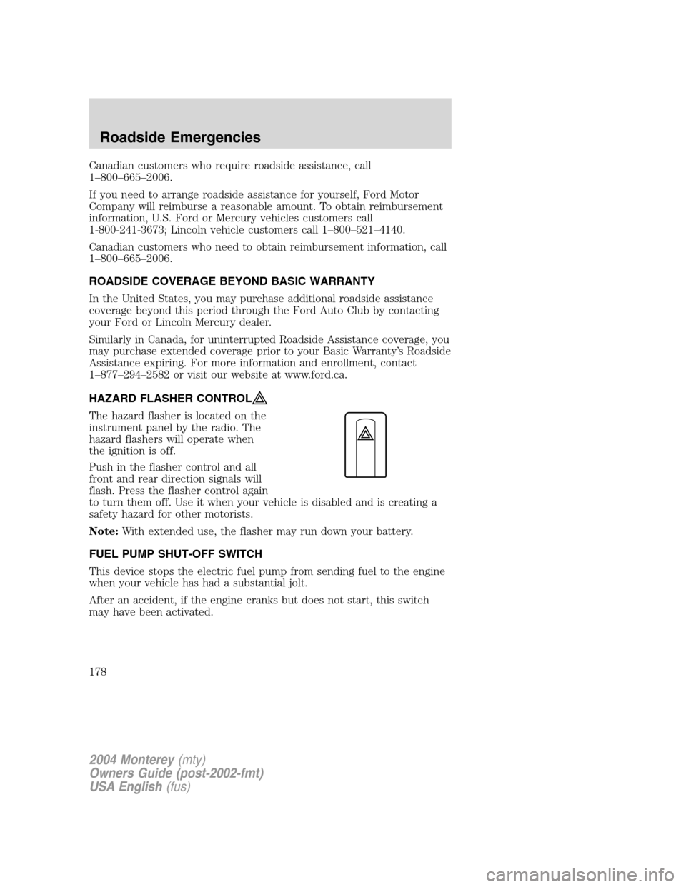
The hazard flasher is located on the
instrument panel by the radio. The
hazard flashers will operate when
the ignition is off.
Push in the flasher control and all
front and rear direction signals will
flash. Press the flasher control again
to turn them off. Use it when your vehicle is disabled and is creating a
safety hazard for other motorists.
Note:With extended use, the flasher may run down your battery.
FUEL PUMP SHUT-OFF SWITCH
This device stops the electric fuel pump from sending fuel to the engine
when your vehicle has had a substantial jolt.
After an accident, if the engine cranks but does not start, this switch
may have been activated.
2004 Monterey(mty)
Owners Guide (post-2002-fmt)
USA English(fus)
Roadside Emergencies
178
Page 183 of 272
Always disconnect the battery before servicing high current
fuses.
Always replace the cover to the power distribution box before
reconnecting the battery or refilling fluid reservoirs
If the battery has been disconnected and reconnected, refer to the
Batterysection of theMaintenance and specificationschapter.
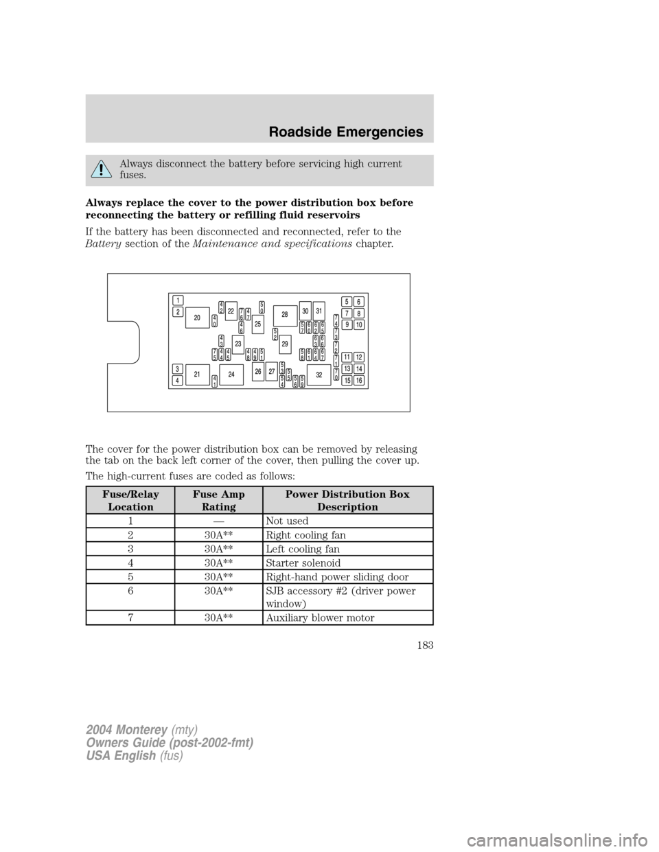
The cover for the power distribution box can be removed by releasing
the tab on the back left corner of the cover, then pulling the cover up.
The high-current fuses are coded as follows:
Fuse/Relay
LocationFuse Amp
RatingPower Distribution Box
Description
1—Not used
2 30A** Right cooling fan
3 30A** Left cooling fan
4 30A** Starter solenoid
5 30A** Right-hand power sliding door
6 30A** SJB accessory #2 (driver power
window)
7 30A** Auxiliary blower motor
2004 Monterey(mty)
Owners Guide (post-2002-fmt)
USA English(fus)
Roadside Emergencies
183
Page 194 of 272
4. Check that the tire lies flat against the frame and is properly
tightened. Try to push or pull, then turn the tire to be sure it will not
move. Loosen and retighten, if necessary. Failure to properly stow the
spare tire may result in failure of the winch cable and loss of the tire.
5. Repeat this tightness check procedure when servicing the spare tire
pressure (every six months, per scheduled maintenance guide), or at any
time that the spare tire is disturbed through service of other
components.
6. If removed, install the spare tire lock (if equipped) into the bumper
drive tube with the spare tire lock key (if equipped) and jack handle.
Wheel lug nut torque specifications
Retighten the lug nuts to the specified torque at 800 km (500 miles)
after any wheel disturbance (rotation, flat tire, wheel removal, etc.).
Bolt size Wheel lug nut torque*
Nm Lb-ft
1⁄2x 20 113-153 85-115
* Torque specifications are for nut and bolt threads free of dirt and
rust. Use only Ford recommended replacement fasteners.
When a wheel is installed, always remove any corrosion, dirt or
foreign materials present on the mounting surfaces of the wheel or
the surface of the front disc brake hub and rotor that contacts the wheel.
Installing wheels without correct metal-to-metal contact at the wheel
mounting surfaces can cause the wheel nuts to loosen and the wheel to
come off while the vehicle is in motion, resulting in loss of control.
JUMP STARTING YOUR VEHICLE
The gases around the battery can explode if exposed to flames,
sparks, or lit cigarettes. An explosion could result in injury or
vehicle damage.
Batteries contain sulfuric acid which can burn skin, eyes and
clothing, if contacted.
Do not attempt to push-start your vehicle. Automatic
transmissions do not have push-start capability; doing so may
damage the catalytic converter.
2004 Monterey(mty)
Owners Guide (post-2002-fmt)
USA English(fus)
Roadside Emergencies
194
Page 195 of 272

Preparing your vehicle
When the battery is disconnected or a new battery is installed, the
transmission must relearn its shift strategy. As a result, the transmission
may have firm and/or soft shifts. This operation is considered normal and
will not affect function or durability of the transmission. Over time, the
adaptive learning process will fully update transmission operation.
1.Use only a 12–volt supply to start your vehicle.
2. Do not disconnect the battery of the disabled vehicle as this could
damage the vehicle’s electrical system.
3. Park the booster vehicle close to the hood of the disabled vehicle
making sure the two vehiclesdo nottouch. Set the parking brake on
both vehicles and stay clear of the engine cooling fan and other moving
parts.
4. Check all battery terminals and remove any excessive corrosion before
you attach the battery cables. Ensure that vent caps are tight and level.
5. Turn the heater fan on in both vehicles to protect any electrical
surges. Turn all other accessories off.
Connecting the jumper cables
1. Connect the positive (+) jumper cable to the positive (+) terminal of
the discharged battery.
Note:In the illustrations,lightning boltsare used to designate the
assisting (boosting) battery.
+–+–
2004 Monterey(mty)
Owners Guide (post-2002-fmt)
USA English(fus)
Roadside Emergencies
195
Page 196 of 272
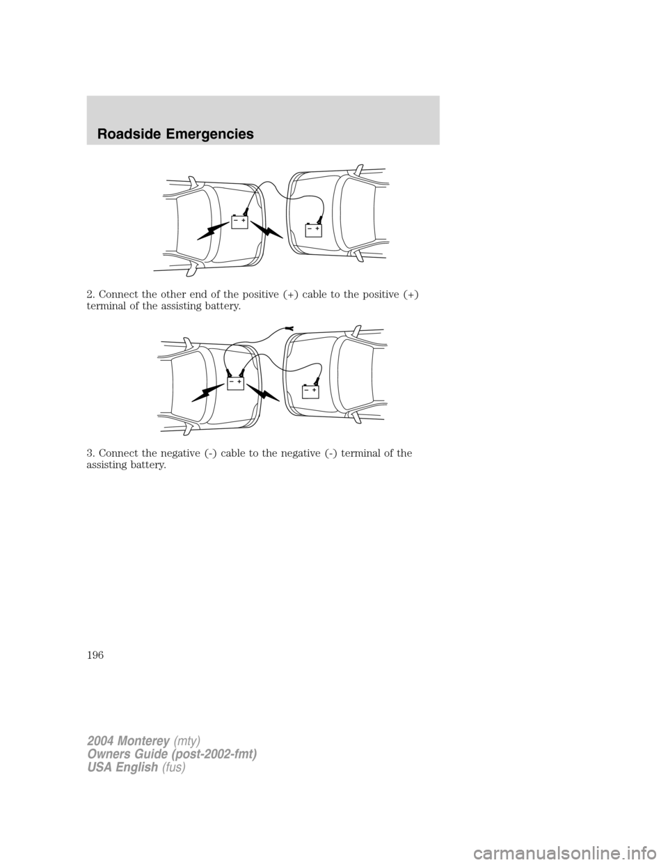
2. Connect the other end of the positive (+) cable to the positive (+)
terminal of the assisting battery.
3. Connect the negative (-) cable to the negative (-) terminal of the
assisting battery.
+–+–
+–+–
2004 Monterey(mty)
Owners Guide (post-2002-fmt)
USA English(fus)
Roadside Emergencies
196
Page 197 of 272

4. Make the final connection of the negative (-) cable to an exposed
metal part of the stalled vehicle’s engine, away from the battery and the
carburetor/fuel injection system.Do notuse fuel lines, engine rocker
covers or the intake manifold asgroundingpoints.
Do not connect the end of the second cable to the negative (-)
terminal of the battery to be jumped. A spark may cause an
explosion of the gases that surround the battery.
5. Ensure that the cables are clear of fan blades, belts, moving parts of
both engines, or any fuel delivery system parts.
Jump starting
1. Start the engine of the booster vehicle and run the engine at
moderately increased speed.
2. Start the engine of the disabled vehicle.
3. Once the disabled vehicle has been started, run both engines for an
additional three minutes before disconnecting the jumper cables.
+–+–
2004 Monterey(mty)
Owners Guide (post-2002-fmt)
USA English(fus)
Roadside Emergencies
197
Page 198 of 272
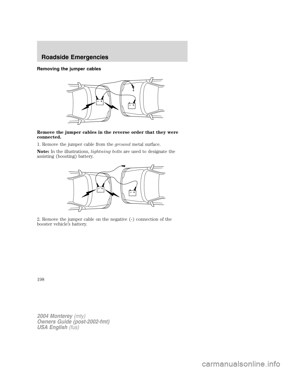
Removing the jumper cables
Remove the jumper cables in the reverse order that they were
connected.
1. Remove the jumper cable from thegroundmetal surface.
Note:In the illustrations,lightning boltsare used to designate the
assisting (boosting) battery.
2. Remove the jumper cable on the negative (-) connection of the
booster vehicle’s battery.
+–+–
+–+–
2004 Monterey(mty)
Owners Guide (post-2002-fmt)
USA English(fus)
Roadside Emergencies
198
Page 199 of 272

3. Remove the jumper cable from the positive (+) terminal of the booster
vehicle’s battery.
4. Remove the jumper cable from the positive (+) terminal of the
disabled vehicle’s battery.
After the disabled vehicle has been started and the jumper cables
removed, allow it to idle for several minutes so the engine computer can
relearnits idle conditions.
+–+–
+–+–
2004 Monterey(mty)
Owners Guide (post-2002-fmt)
USA English(fus)
Roadside Emergencies
199