turn signal Mercury Monterey 2005 s User Guide
[x] Cancel search | Manufacturer: MERCURY, Model Year: 2005, Model line: Monterey, Model: Mercury Monterey 2005Pages: 304, PDF Size: 3.45 MB
Page 97 of 304

Sounding a panic alarm
Press
to activate the alarm. The alarm will cycle the horn, the turn
signals will flash, and the interior lamps will illuminate.
Press again or turn the ignition to the 4 (ON) or the 1 (ACCESSORY)
position to deactivate.
Replacing the battery
The remote entry transmitter uses one coin type three-volt lithium
battery CR2032 or equivalent.
To replace the battery:
1. Twist a thin coin between the two
halves of the remote entry
transmitter near the key ring. DO
NOT TAKE THE RUBBER COVER
AND CIRCUIT BOARD OFF THE
FRONT HOUSING OF THE
REMOTE ENTRY TRANSMITTER.
2. Do not wipe off any grease on the
battery terminals on the back
surface of the circuit board.
3. Remove the old battery.Note:Please refer to local regulations when
disposing of transmitter batteries.
4. Insert the new battery. Refer to the diagram inside the remote entry
transmitter for the correct orientation of the battery. Press the battery
down to ensure that the battery is fully seated in the battery housing
cavity.
5. Snap the two halves back together.
Note:Replacement of the battery willnotcause the remote transmitter
to become deprogrammed from your vehicle. The remote transmitter
should operate normally after battery replacement.
2005 Monterey(mty)
Owners Guide (post-2002-fmt)
USA_English(fus)
Locks and Security
97
Page 107 of 304

5. Within 10 seconds of removing the secondcoded key,insert the new
unprogrammed key (new key/valet key) into the ignition and turn the
ignition from the 3 (OFF) position to the 4 (ON) position [maintain
ignition in the 4 (ON) position for at least three seconds, but no more
than ten seconds]. This step will program your new key to a coded key.
6. To program additional new unprogrammed key(s), repeat this
procedure from step 1.
If successful, the new coded key(s) will start the vehicle’s engine and the
theft indicator will illuminate for three seconds and then go out.
If not successful, the new coded key(s) will not start the vehicle’s engine
and the theft indicator will flash on and off and you may repeat Steps 1
through 5. If failure repeats, bring your vehicle to your dealership to
have the new spare key(s) programmed.
PERIMETER ALARM SYSTEM (IF EQUIPPED)
The perimeter anti-theft system will warn you in the event of an
unauthorized entry to your vehicle.
If there is any potential perimeter anti-theft problem with your vehicle,
ensureALL remote entry transmittersare taken to the dealership to
aid in troubleshooting.
Arming the system
When armed, this system will help protect your vehicle from
unauthorized entry. When unauthorized entry occurs, the system will
flash the turn signal lamps and side repeaters and honk the horn.
The system is ready to arm whenever the key is removed from the
ignition. Any of the following actions will prearm the alarm system:
•Locking the vehicle using the remote entry transmitter.
•Locking the vehicle using the keyless entry keypad.
•Pressing the interior power door lock control while the door is open.
Twenty seconds after one of the above events occurs, any door/hood that
is closed is armed.
Any door/hood that is still open is prearmed and waiting for the
door/hood to be closed.
Once that input is closed, the input will arm in 20 seconds and the
exterior lamps may flash.
Disarming the system
You can disarm the system by any of the following actions:
•Unlock the vehicle with the remote keyless transmitter.
2005 Monterey(mty)
Owners Guide (post-2002-fmt)
USA_English(fus)
Locks and Security
107
Page 203 of 304

Safety chains
Always connect the trailer’s safety chains to the hook retainers on the
hitch. To connect the trailer’s safety chains, cross the chains under the
trailer tongue and allow slack for turning corners.
If you use a rental trailer, follow the instructions that the rental agency
gives to you.
Do not attach safety chains to the bumper.
Trailer brakes
Be sure your trailer conforms to all applicable local and Federal
Regulations regarding trailer braking. If your trailer is equipped with
electronically controlled brakes you will need to have an electronic brake
controller with associated wiring installed to your vehicle by a qualified
technician.
Do not connect a trailer’s hydraulic brake system directly to your
vehicle’s brake system. Your vehicle may not have enough
braking power and your chances of having a collision greatly increase.
The braking system of the tow vehicle is rated for operation at the
GVWR not GCWR.
Trailer lamps
Trailer lamps are required on most towed vehicles. Make sure all running
lights, brake lights, turn signals and hazard lights are working.
Do not splice into the vehicle lamp wiring for trailer lamps. Your
vehicle uses an advanced electronic module to control and
monitor your vehicle lamps. Splicing into the wiring or attaching
wiring to the vehicle bulb. may DISABLE the rear vehicle lamps
or cause them not to function properly. Your lamp outage feature
may also be disabled or provide incorrect information.
See your dealer or trailer rental agency for proper instructions and
equipment for hooking up trailer lamps.
2005 Monterey(mty)
Owners Guide (post-2002-fmt)
USA_English(fus)
Tires, Wheels and Loading
203
Page 223 of 304

Canadian customers who require roadside assistance, call
1–800–665–2006.
If you need to arrange roadside assistance for yourself, Ford Motor
Company will reimburse a reasonable amount. To obtain reimbursement
information, U.S. Ford or Mercury vehicles customers call
1-800-241-3673; Lincoln vehicle customers call 1–800–521–4140.
Canadian customers who need to obtain reimbursement information, call
1–800–665–2006.
ROADSIDE COVERAGE BEYOND BASIC WARRANTY
In the United States, you may purchase additional roadside assistance
coverage beyond this period through the Ford Auto Club by contacting
your Ford or Lincoln Mercury dealer.
Similarly in Canada, for uninterrupted Roadside Assistance coverage, you
may purchase extended coverage prior to your Basic Warranty’s Roadside
Assistance expiring. For more information and enrollment, contact
1–877–294–2582 or visit our website at www.ford.ca.
HAZARD FLASHER CONTROL
The hazard flasher is located on the
instrument panel by the radio. The
hazard flashers will operate when
the ignition is in any position or if
the key is not in the ignition.
Push in the flasher control and all
front and rear direction signals will
flash. Press the flasher control again to turn them off. Use it when your
vehicle is disabled and is creating a safety hazard for other motorists.
Note:With extended use, the flasher may run down your battery.
FUEL PUMP SHUT-OFF SWITCH
This device stops the electric fuel pump from sending fuel to the engine
when your vehicle has had a substantial jolt.
After an accident, if the engine cranks but does not start, this switch
may have been activated.
2005 Monterey(mty)
Owners Guide (post-2002-fmt)
USA_English(fus)
Roadside Emergencies
223
Page 231 of 304

Fuse/Relay
LocationFuse Amp
RatingPower Distribution Box
Description
61 20A* Spare
62 30A* SJB #3 – Right cornering/auxiliary
lamps, Right low beam, Left front
park/turn lamps, Left rear
park/stop/turn lamps, Instrument
panel courtesy lamps, Step well
lamps, Left signal mirror, Clock,
Cluster, Message center (SJB
F–15), Switch illumination for:
overhead console, DVD/Rear
climate control system, Headlamp
switch illumination, Climate
control illumination
63 20A* Instrument panel power point,
Cigar lighter
64 20A* Ignition switch #1 feed
65 30A* SJB #2 – Left cornering/auxiliary
lamps, Left low beam, Right front
park/turn lamps, Right rear
park/stop/turn lamps, Puddle
lamps, Mirror signals, Visors, 2nd
and 3rd row lamps, Cargo lamp,
Defroster indicator
66 20A*
2nd and 3rd row seat power points
67 20A* Ignition switch #2 feed
70 — Not used
71 — Not used
72 — Not used
73 — Not used
74 — Not used
75 Diode PCM
76 Diode A/C clutch
* Mini Fuse ** Cartridge Fuse
2005 Monterey(mty)
Owners Guide (post-2002-fmt)
USA_English(fus)
Roadside Emergencies
231
Page 298 of 304

bulb replacement
specifications chart ..................48
daytime running light ...............42
fog lamps ...................................41
headlamps .................................41
headlamps, flash to pass ..........43
instrument panel, dimming .....44
interior lamps .....................46–48
replacing bulbs ...................48–52
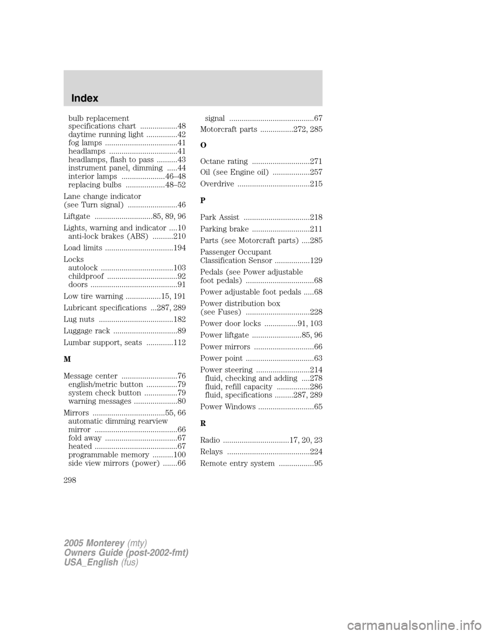
Lane change indicator
(see Turn signal) ........................46
Liftgate ............................85, 89, 96
Lights, warning and indicator ....10
anti-lock brakes (ABS) ..........210
Load limits .................................194
Locks
autolock ...................................103
childproof ..................................92
doors ..........................................91
Low tire warning .................15, 191
Lubricant specifications ...287, 289
Lug nuts ....................................182
Luggage rack ...............................89
Lumbar support, seats .............112
M
Message center ...........................76
english/metric button ...............79
system check button ................79
warning messages .....................80
Mirrors ...................................55, 66
automatic dimming rearview
mirror ........................................66
fold away ...................................67
heated ........................................67
programmable memory ..........100
side view mirrors (power) .......66signal .........................................67
Motorcraft parts ................272, 285
O
Octane rating ............................271
Oil (see Engine oil) ..................257
Overdrive ...................................215
P
Park Assist ................................218
Parking brake ............................211
Parts (see Motorcraft parts) ....285
Passenger Occupant
Classification Sensor .................129
Pedals (see Power adjustable
foot pedals) .................................68
Power adjustable foot pedals .....68
Power distribution box
(see Fuses) ...............................228
Power door locks ................91, 103
Power liftgate ........................85, 96
Power mirrors .............................66
Power point .................................63
Power steering ..........................214
fluid, checking and adding ....278
fluid, refill capacity ................286
fluid, specifications .........287, 289
Power Windows ...........................65
R
Radio ................................17, 20, 23
Relays ........................................224
Remote entry system .................95
2005 Monterey(mty)
Owners Guide (post-2002-fmt)
USA_English(fus)
Index
298
Page 300 of 304

Transmission
brake-shift interlock (BSI) ....214
fluid, checking and adding
(automatic) .............................279
lubricant specifications ..........287
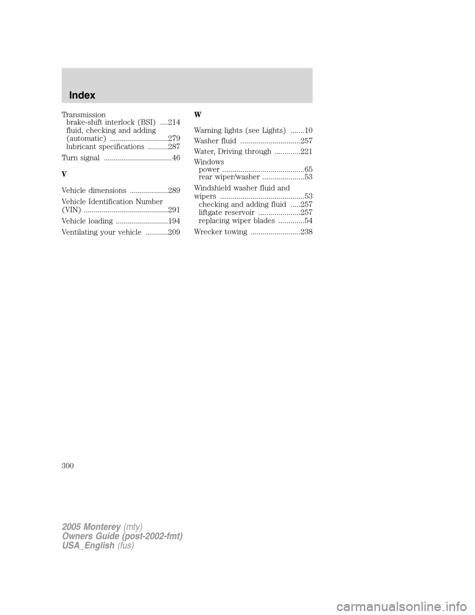
Turn signal ..................................46
V
Vehicle dimensions ...................289
Vehicle Identification Number
(VIN) ..........................................291
Vehicle loading ..........................194
Ventilating your vehicle ...........209W
Warning lights (see Lights) .......10
Washer fluid ..............................257
Water, Driving through .............221
Windows
power .........................................65
rear wiper/washer .....................53
Windshield washer fluid and
wipers ..........................................53
checking and adding fluid .....257
liftgate reservoir .....................257
replacing wiper blades .............54
Wrecker towing .........................238
2005 Monterey(mty)
Owners Guide (post-2002-fmt)
USA_English(fus)
Index
300