clock Mercury Monterey 2006 s User Guide
[x] Cancel search | Manufacturer: MERCURY, Model Year: 2006, Model line: Monterey, Model: Mercury Monterey 2006Pages: 320, PDF Size: 3.57 MB
Page 66 of 320
POWER SIDE VIEW MIRRORS
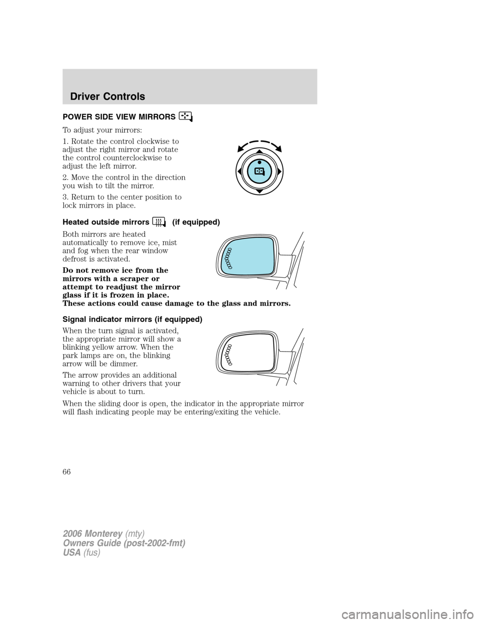
To adjust your mirrors:
1. Rotate the control clockwise to
adjust the right mirror and rotate
the control counterclockwise to
adjust the left mirror.
2. Move the control in the direction
you wish to tilt the mirror.
3. Return to the center position to
lock mirrors in place.
Heated outside mirrors
(if equipped)
Both mirrors are heated
automatically to remove ice, mist
and fog when the rear window
defrost is activated.
Do not remove ice from the
mirrors with a scraper or
attempt to readjust the mirror
glass if it is frozen in place.
These actions could cause damage to the glass and mirrors.
Signal indicator mirrors (if equipped)
When the turn signal is activated,
the appropriate mirror will show a
blinking yellow arrow. When the
park lamps are on, the blinking
arrow will be dimmer.
The arrow provides an additional
warning to other drivers that your
vehicle is about to turn.
When the sliding door is open, the indicator in the appropriate mirror
will flash indicating people may be entering/exiting the vehicle.
2006 Monterey(mty)
Owners Guide (post-2002-fmt)
USA(fus)
Driver Controls
66
Page 231 of 320

The fuses are coded as follows:
Fuse/Relay
LocationFuse Amp
RatingPassenger Compartment Fuse
Panel Description
1 Relay Accessory delay relay 1
2 Relay Accessory delay relay 2
3 10A Front wiper motor Run feed
4 5A B+ feed to outside mirrors
5 20A Vent window power feed/Radio
feed
6 5A Driver door switch
illumination/Passenger door
switch illumination
7 10A Rear wiper Run feed
8 10A Cluster/Electronic Automatic
Temperature Control (EATC) B+
feed, DVD
9 10A Passive Anti-theft System (PATS)
LED feed
10 5A Auxiliary radio
11 5A Auxiliary climate control
system/Power Liftgate
Module/Left and right power
sliding door module/Data Link
Connector (DLC)/Clock B+ feeds
2006 Monterey(mty)
Owners Guide (post-2002-fmt)
USA(fus)
Roadside Emergencies
231
Page 236 of 320
Fuse/Relay
LocationFuse Amp
RatingPower Distribution Box
Description
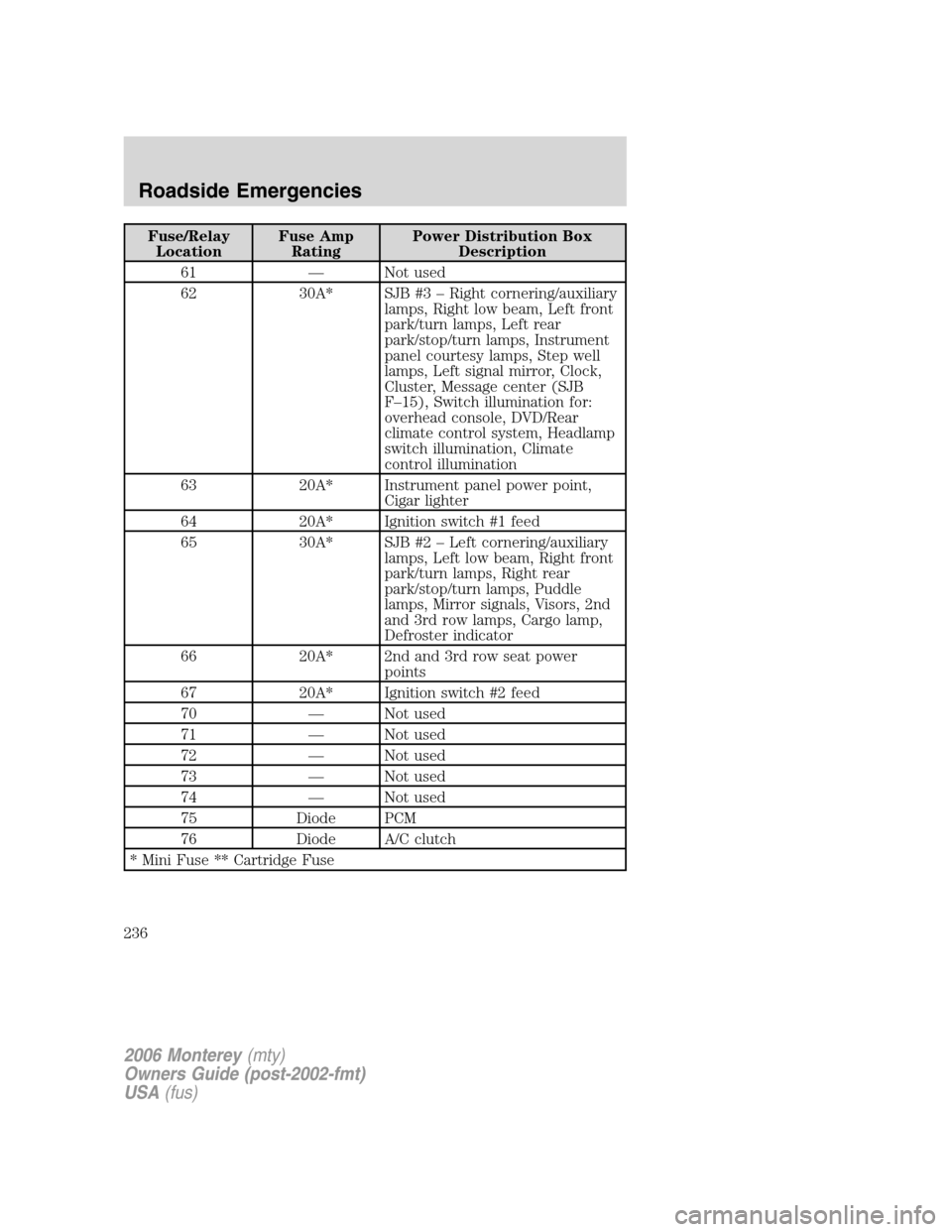
61 — Not used
62 30A* SJB #3 – Right cornering/auxiliary
lamps, Right low beam, Left front
park/turn lamps, Left rear
park/stop/turn lamps, Instrument
panel courtesy lamps, Step well
lamps, Left signal mirror, Clock,
Cluster, Message center (SJB
F–15), Switch illumination for:
overhead console, DVD/Rear
climate control system, Headlamp
switch illumination, Climate
control illumination
63 20A* Instrument panel power point,
Cigar lighter
64 20A* Ignition switch #1 feed
65 30A* SJB #2 – Left cornering/auxiliary
lamps, Left low beam, Right front
park/turn lamps, Right rear
park/stop/turn lamps, Puddle
lamps, Mirror signals, Visors, 2nd
and 3rd row lamps, Cargo lamp,
Defroster indicator
66 20A* 2nd and 3rd row seat power
points
67 20A* Ignition switch #2 feed
70 — Not used
71 — Not used
72 — Not used
73 — Not used
74 — Not used
75 Diode PCM
76 Diode A/C clutch
* Mini Fuse ** Cartridge Fuse
2006 Monterey(mty)
Owners Guide (post-2002-fmt)
USA(fus)
Roadside Emergencies
236
Page 241 of 320
Have a flat tire serviced by an authorized dealer in order to prevent
damage to the TPMS sensor, refer toTire Pressure Monitoring System
(TPMS)in theTires, Wheels and Loadingchapter. Replace the spare
tire with a road tire as soon as possible.
The spare tire and tools for your vehicle are stowed in the following
locations:
Item Location
Spare tire Under the vehicle, just forward of
the rear bumper.
Jack Behind the access panel located
on the right rear quarter panel
interior trim.
Jack handle Attached to the jack with a clip.
Flat tire tether, wing screw Inside tire tether kit, next to jack.
Removing the jack and tools
1. Locate the access panel on the interior trim. Rotate the panel
retaining clip and remove the panel.
2. Remove the jack and lug nut wrench by turning the thumbscrew
counterclockwise to relieve tension against the stowage bracket.
Removing the spare tire
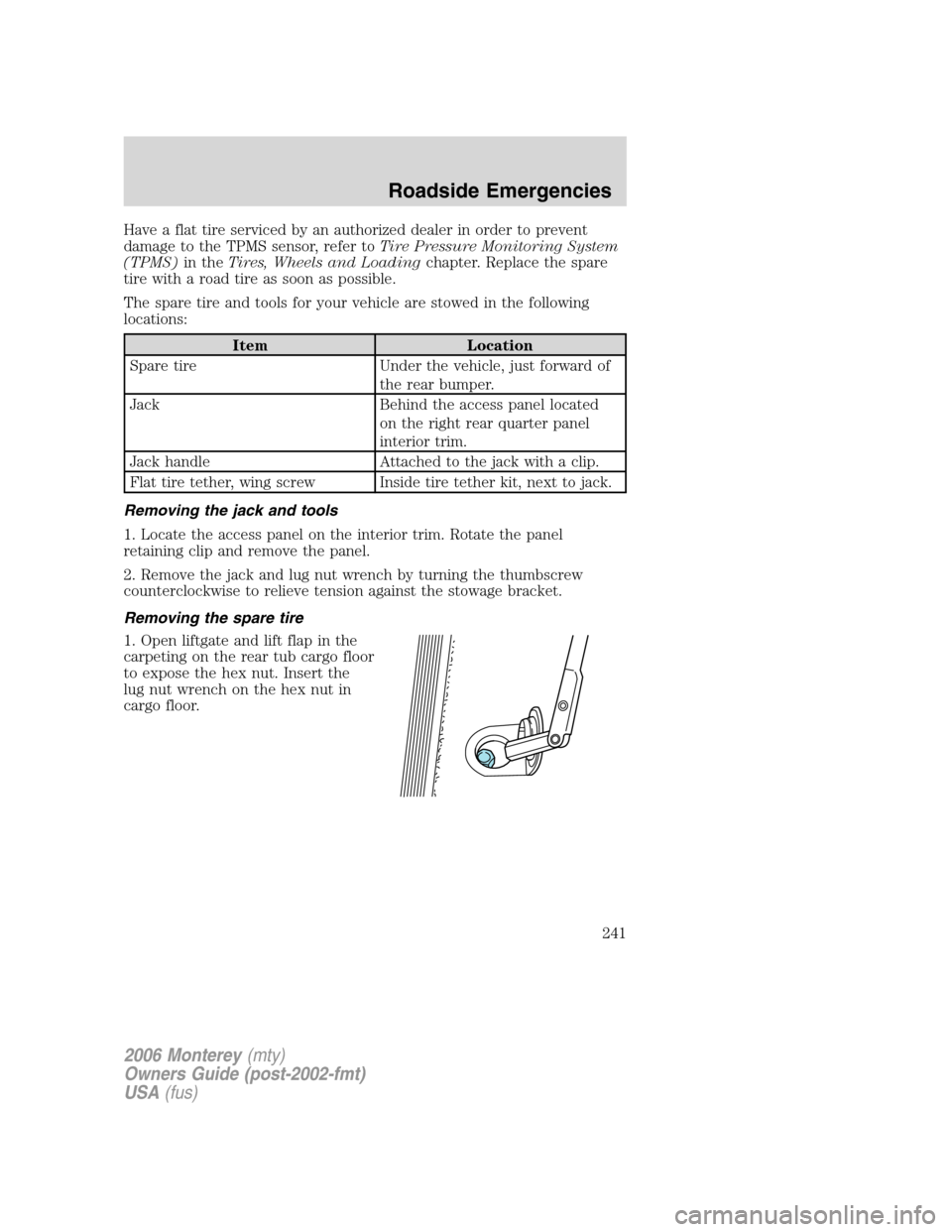
1. Open liftgate and lift flap in the
carpeting on the rear tub cargo floor
to expose the hex nut. Insert the
lug nut wrench on the hex nut in
cargo floor.
2006 Monterey(mty)
Owners Guide (post-2002-fmt)
USA(fus)
Roadside Emergencies
241
Page 242 of 320

2. Turn the wrench
counterclockwise until cable is slack
and tire can be slid rearward.
3. Remove the primary retainer from
the center of the tire.
Note:Do not stow the full size tire or any flat tire under the vehicle.
Stowing the primary tether
Note:Ifno tireis to be stowed
under the vehicle, raise the primary
tether by turning the wrench
clockwise until the hex nut ratchets.
Tire change procedure
When one of the front wheels is off the ground, the transaxle
alone will not prevent the vehicle from moving or slipping off the
jack, even if the vehicle is in P (Park).
To help prevent the vehicle from moving when you change a tire,
be sure the parking brake is set, then block (in both directions)
the wheel that is diagonally opposite (other side and end of the
vehicle) to the tire being changed.
If the vehicle slips off the jack, you or someone else could be
seriously injured.
2006 Monterey(mty)
Owners Guide (post-2002-fmt)
USA(fus)
Roadside Emergencies
242
Page 243 of 320

1. Park on a level surface, activate
hazard flashers and set parking
brake.
2. Place gearshift lever in P (Park),
turn engine off, and block the
diagonally opposite wheel.
3. Remove the spare tire, jack and
lug wrench.
4. Removing the optional wheel
cover or center ornament:
•To remove a bolt-on wheel cover
(if equipped) loosen the plastic
nuts on the center ornament with
the wheel nut wrench. Then,
remove the wheel cover with the
tapered end of the wheel nut
wrench.
•Remove the center ornament (if
equipped) from the wheel with the tapered end of the wheel nut
wrench. Insert and twist the handle, then pry against the wheel.
5. Loosen each wheel lug nut
one-half turn counterclockwise but
do not remove them until the wheel
is raised off the ground.
2006 Monterey(mty)
Owners Guide (post-2002-fmt)
USA(fus)
Roadside Emergencies
243
Page 244 of 320

If Ford Accessory Running Boards
have been installed, use the jack
adapters supplied with the running
boards as described on the inside of
the jack storage area.
6. Locate the jack notch next to the
door closest to the tire you are
changing, then place the jack on the
frame rail directly behind the notch.
7. Turn the jack handle clockwise
until the wheel is completely off the
ground.
To lessen the risk of
personal injury, do not put
any part of your body under the
vehicle while changing a tire. Do
not start the engine when your
vehicle is on the jack. The jack is
only meant for changing the tire.
8. Remove the lug nuts with the lug wrench.
9. Replace the flat tire with the spare tire, making sure the valve stem is
facing outward. Reinstall lug nuts until the wheel is snug against the hub.
Do not fully tighten the lug nuts until the wheel has been lowered.
10. Lower the wheel by turning the jack handle counterclockwise.
2006 Monterey(mty)
Owners Guide (post-2002-fmt)
USA(fus)
Roadside Emergencies
244
Page 245 of 320

11. Remove the jack and fully
tighten the lug nuts in the order
shown. Refer toWheel lug nut
torque specificationslater in this
chapter for the proper lug nut
torque specification.
12. Installing the optional wheel
cover or center ornament:
•If equipped with a bolted-on
wheel cover, install the wheel
cover and tighten the five plastic nuts until they click (do not use
power tools on these nuts).
•If equipped with the center ornament, install the center ornament by
snapping it back into place.
13. Put flat tire, jack and lug wrench away in the proper stowage
locations.
Stowing the flat and full-size tire
Failure to follow these instructions may result in personal injury.
Do not install the flat tire or any full size tire underneath the
vehicle.
Remove tether kit from the jack storage area.
1. Place tire upright inside the vehicle near the rear of the vehicle with
the valve stem facing the front of the vehicle.
2. Pass the cable retainer through the center of the wheel.
3. Raise the tire and secure both ends of the cable with the wing nut
provided in the tether cable kit, by installing it on the luggage back panel
and turning the wing screw clockwise. You will hear an audible click
when the tire is properly secured.
4. Check that the flat tire is properly secured.
Stowing the spare tire
1. Lay the spare, inflated tire on the ground with the valve stem facing
down.
2. Insert the primary wheel retainer through the center of the wheel.
3. Use the winch mechanism to pull, and raise the tire under the vehicle.
4. Raise the tire by turning the lug nut wrench clockwise until the hex
nut ratchets.
1
4 3
2 5
2006 Monterey(mty)
Owners Guide (post-2002-fmt)
USA(fus)
Roadside Emergencies
245
Page 276 of 320
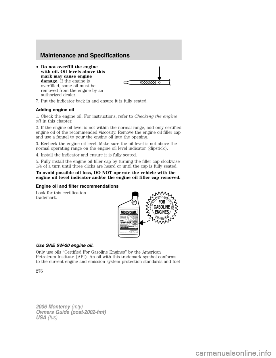
•Do not overfill the engine
with oil. Oil levels above this
mark may cause engine
damage.If the engine is
overfilled, some oil must be
removed from the engine by an
authorized dealer.
7. Put the indicator back in and ensure it is fully seated.
Adding engine oil
1. Check the engine oil. For instructions, refer toChecking the engine
oilin this chapter.
2. If the engine oil level is not within the normal range, add only certified
engine oil of the recommended viscosity. Remove the engine oil filler cap
and use a funnel to pour the engine oil into the opening.
3. Recheck the engine oil level. Make sure the oil level is not above the
normal operating range on the engine oil level indicator (dipstick).
4. Install the indicator and ensure it is fully seated.
5. Fully install the engine oil filler cap by turning the filler cap clockwise
1/4 of a turn until three clicks are heard or until the cap is fully seated.
To avoid possible oil loss, DO NOT operate the vehicle with the
engine oil level indicator and/or the engine oil filler cap removed.
Engine oil and filter recommendations
Look for this certification
trademark.
Use SAE 5W-20 engine oil.
Only use oils “Certified For Gasoline Engines” by the American
Petroleum Institute (API). An oil with this trademark symbol conforms
to the current engine and emission system protection standards and fuel
2006 Monterey(mty)
Owners Guide (post-2002-fmt)
USA(fus)
Maintenance and Specifications
276
Page 279 of 320
installed, the transaxle must relearn its adaptive strategy. Optimal
shifting will resume within a few hundred kilometers (miles) of
operation.
Because your vehicle’s engine is electronically controlled by a computer,
some control conditions are maintained by power from the battery. When
the battery is disconnected or a new battery is installed, the engine must
relearn its idle and fuel trim strategy for optimum driveability and
performance. To begin this process:
1. With the vehicle at a complete stop, set the parking brake.
2. Put the gearshift in P (Park), turn off all accessories and start the
engine.
3. Run the engine until it reaches normal operating temperature.
4. Allow the engine to idle for at least one minute.
5. Turn the A/C on and allow the engine to idle for at least one minute.
6. With your foot on the brake pedal and with the A/C on, put the
vehicle in D (Drive) and allow the engine to idle for at least one minute.
7. Drive the vehicle to complete the relearning process.
•The vehicle may need to be driven 10 miles (16 km) or more to
relearn the idle and fuel trim strategy.
•If you do not allow the engine to relearn its idle trim, the idle
quality of your vehicle may be adversely affected until the idle
trim is eventually relearned.
If the battery has been disconnected or a new battery has been installed,
the clock and the preset radio stations must be reset once the battery is
reconnected.
If the battery has been discharged, disconnected or a new battery has
been installed, the power sliding door may need to be reset. Refer to
Power Sliding Door-Resetting the PSDin theDriver Controlschapter.
2006 Monterey(mty)
Owners Guide (post-2002-fmt)
USA(fus)
Maintenance and Specifications
279