relay Mercury Mountaineer 1997 Owner's Manuals
[x] Cancel search | Manufacturer: MERCURY, Model Year: 1997, Model line: Mountaineer, Model: Mercury Mountaineer 1997Pages: 197, PDF Size: 2.08 MB
Page 34 of 197

3. Slide the delay slide knob to the
center of travel. The further you
move the knob to the right, the
longer the headlamps stay on after
the ignition is turned to the OFF
position. The autolamp will keep
the headlamps on for a maximum
of three minutes after the ignition
is turned off.
4. The autolamp automatically
turns the lamps on and off.
Automatic dimming feature
The autolamp/automatic dimming
mirror is equipped with an
automatic dimming feature. This
feature will change from the
normal state to the non-glare
``active'' state when bright lights
(glare) reach the mirror. When the
mirror detects bright light from the
front or behind, it will adjust
automatically to minimize glare.
The automatic dimming feature is
active when the ignition is turned
to the ON position.
When active, the mirror senses
bright light (glare) from the front
and rear and automatically adjusts
itself to minimize glare.
AUTOLAMP
OFF MAXRELAY
Controls and features
34
Page 101 of 197

on downgrades. Transmission
operates in gears 1-2.
1 - LowUse 1 (Low) to provide
maximum engine braking on steep
downgrades. Upshifts can be made
by shifting to 2 (Second) or to
D(Overdrive). Selecting 1 (Low)
at higher speeds causes a shift to 2
(Second), and will shift to 1 (Low)
after vehicle decelerates to the
proper speed.
Brake-shift interlock
This vehicle is equipped with a
brake-shift interlock feature that
prevents the gearshift from being
moved from P unless the brake
pedal is depressed.
If you cannot move the gearshift
out of P with the brake pedal
depressed:
1. Apply the parking brake.
2. Turn ignition key to LOCK, then
remove the key.
3. Insert the key and turn to OFF.
4. Apply brake pedal and shift to N
(Neutral).
5. Start the vehicle.
If it is necessary to use the above
procedure to move the gearshift, it
is possible that a fuse has blown
and the vehicle's brakelamps may
not be operating properly. Refer to
Fuses and relaysin theRoadside
emergencieschapter.
Driving
101
Page 119 of 197

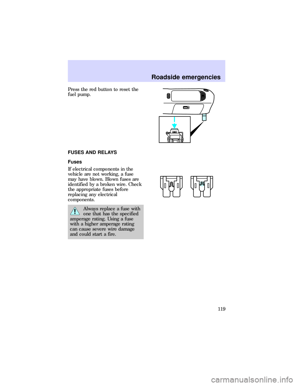
Press the red button to reset the
fuel pump.
FUSES AND RELAYS
Fuses
If electrical components in the
vehicle are not working, a fuse
may have blown. Blown fuses are
identified by a broken wire. Check
the appropriate fuses before
replacing any electrical
components.
Always replace a fuse with
one that has the specified
amperage rating. Using a fuse
with a higher amperage rating
can cause severe wire damage
and could start a fire.
Roadside emergencies
119
Page 121 of 197

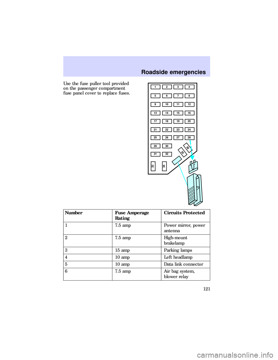
Use the fuse puller tool provided
on the passenger compartment
fuse panel cover to replace fuses.
Number Fuse Amperage
RatingCircuits Protected
1 7.5 amp Power mirror, power
antenna
2 7.5 amp High-mount
brakelamp
3 15 amp Parking lamps
4 10 amp Left headlamp
5 10 amp Data link connector
6 7.5 amp Air bag system,
blower relay
1 234
5 678
9 101112
13 14 15 16
17 18 19 20
21 22 23 24
25 26
29 30
35 3631 32
33
34
27 28
Roadside emergencies
121
Page 122 of 197

Number Fuse Amperage
RatingCircuits Protected
7 7.5 amp Illumination switches
8 10 amp Right headlamp, fog
lamp system
9 10 amp Autolamps
10 7.5 amp Rear blower, speed
control, GEM system,
brake interlock,
overhead console
11 7.5 amp Warning lamps
12 10 amp Liftgate wiper/washer,
front washer
13 15 amp Brake on/off switch
14 10 amp Anti-lock system
15 7.5 amp Air bag system,
instrument cluster
16 30 amp Wiper run relay
17 15 amp Cigar lighter
18 15 amp A/C system
19 25 amp Ignition coil, PCM
system
20 7.5 amp Radio, power antenna,
GEM system,
anti-theft
21 15 amp Turn/hazard flasher
22 10 amp Turn signals
23 10 amp Rear wiper system
24 10 amp Anti-theft relay
25 7.5 amp Instrument cluster,
GEM system
Roadside emergencies
122
Page 123 of 197

Number Fuse Amperage
RatingCircuits Protected
26 10 amp 4R70W overdrive,
DRL system, backup
lamps, rear defroster
relay
27 10 amp Underhood lamp, map
lights, glove box lamp,
overhead lamp, visor
lamps, accessory
delay, dimmer switch
illumination
28 7.5 amp GEM system
29 10 amp Audio system
30 - Not used
31 7.5 amp Rear blower motor
relay
32 7.5 amp Heated rear window
33 15 amp DRL module, RH and
LH headlamp,
instrument cluster
34 7.5 amp Luxury audio system
35 - Not used
36 - Not used
Roadside emergencies
123
Page 125 of 197

High Current Fuse Rating Color
20 amp Yellow
30 amp Light green
40 amp Orange
50 amp Red
60 amp Blue
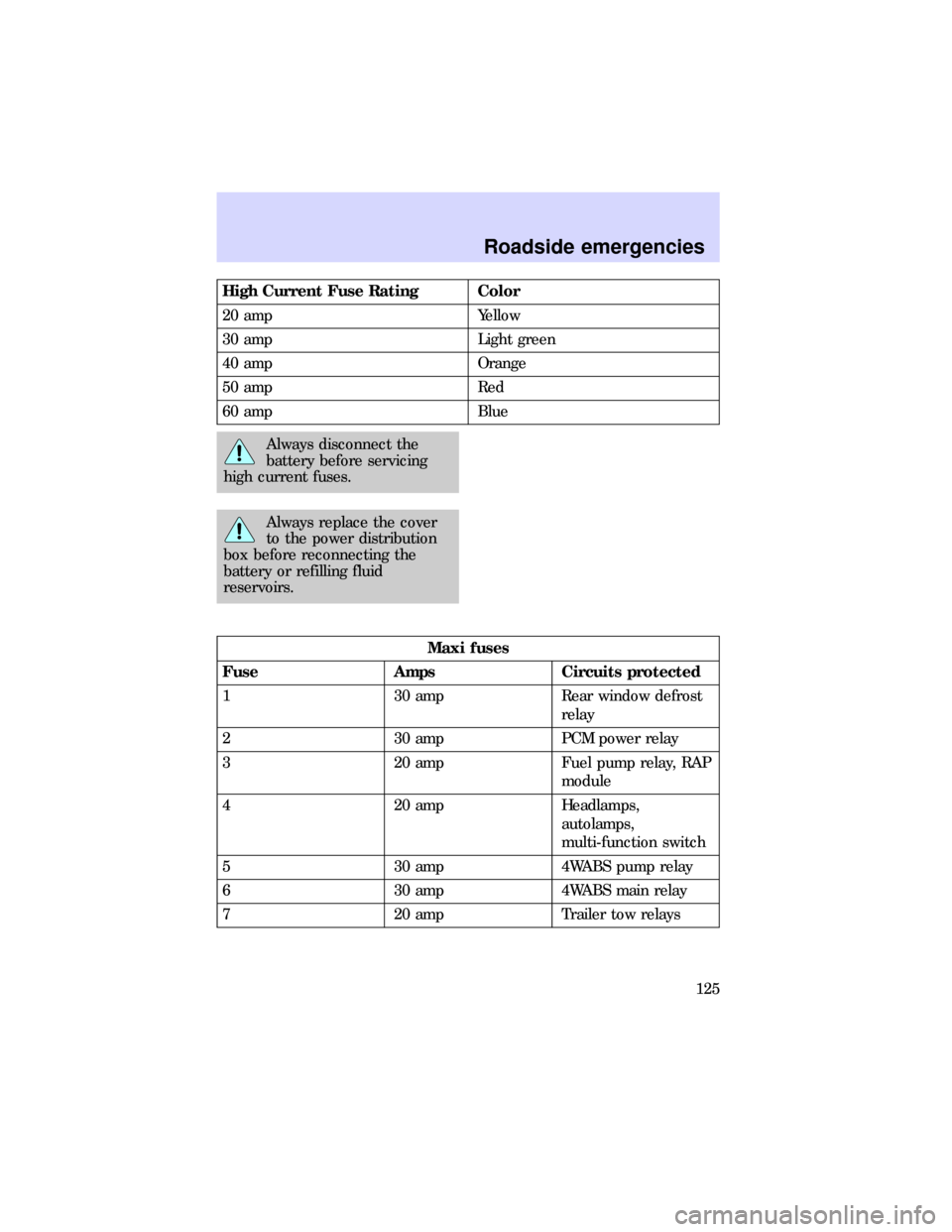
Always disconnect the
battery before servicing
high current fuses.
Always replace the cover
to the power distribution
box before reconnecting the
battery or refilling fluid
reservoirs.
Maxi fuses
Fuse Amps Circuits protected
1 30 amp Rear window defrost
relay
2 30 amp PCM power relay
3 20 amp Fuel pump relay, RAP
module
4 20 amp Headlamps,
autolamps,
multi-function switch
5 30 amp 4WABS pump relay
6 30 amp 4WABS main relay
7 20 amp Trailer tow relays
Roadside emergencies
125
Page 126 of 197

Maxi fuses
Fuse Amps Circuits protected
8 30 amp Battery saver relay,
headlamp relay
9 50 amp Blower motor relay,
blower motor
10 30 amp Power seats, power
lumbar, door
lock/unlock relays,
accessory delay relay
11 20 amp Horn relay,
Powertrain control
module (PCM)
12 - Not used
13 60 amp Hazard flasher, brake
ON/OFF switch, cigar
lighter, power
antenna, power
mirrors, autolamps,
instrument cluster,
GEM, radio, blower
motor relay
14 60 amp Ignition switch
Mini fuses
Fuse Amps Circuits protected
1 30 amp Premium sound
2 15 amp Liftgate wiper relays
3 30 amp Auxiliary power
4 10 amp Air bag diagnostic
monitor
5 - Not used
Roadside emergencies
126
Page 127 of 197

Mini fuses
Fuse Amps Circuits protected
6 15 amp Generator/voltage
regulator
7 20 amp Not used
8 15 amp Foglamp relay,
daytime running lamp
module
9 - Not used
10 - Not used
11 20 amp HEGO system
Relays
Relays are located in the power
distribution box.
Relays receive signals from
components or systems and
transfer these signals to activate or
deactivate other components or
systems.
Mercury recommends that relays
be replaced by a qualified
technician.
6
5
3
2
14 21
Roadside emergencies
127
Page 128 of 197

Relay number Circuits connected
1 Wiper run relay
2 Horn relay
3 Wiper HI/LO relay
4 WOT A/C relay
5 PCM power relay
6 Fuel pump relay
Diode number Circuits connected
1 ABS diode
2 PCM diode
CHANGING TIRES
Tire change procedure
1. Park on a level surface.
2. Activate the hazard flashers.
3. Set the parking brake.
4. Place the gearshift in P (Park).
5. Block the diagonally opposite
wheel.
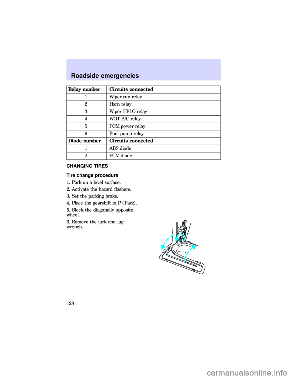
6. Remove the jack and lug
wrench.
Roadside emergencies
128