clock Mercury Mountaineer 1998 Owner's Manuals
[x] Cancel search | Manufacturer: MERCURY, Model Year: 1998, Model line: Mountaineer, Model: Mercury Mountaineer 1998Pages: 216, PDF Size: 1.72 MB
Page 16 of 216

HEADLAMP CONTROL
Rotate the headlamp control
clockwise to the first position to
turn on the parking lamps only.
Rotate to the second position to
also turn on the headlamps.
Foglamp control (if equipped)
Turn on the low-beam headlamps
and press the foglamp control to
activate the foglamps. The foglamp
control button will illuminate when
the foglamps are on.
Press the foglamp control a second
time to deactivate the foglamps.
Daytime running lamps (DRL)
(if equipped)
Turns the highbeam headlamps on
with a reduced output. To activate:
²the engine must be running
²the gearshift must not be in P
(Park)
²the headlamp control is in the
OFF or Parking lamps position.
The Daytime Running
Light (DRL) system will
not illuminate the tail lamps and
parking lamps. Turn on your
headlamps at dusk. Failure to do
so may result in a collision.
OFF
Controls and features
16
Page 145 of 216

a tire could result in damage to
driveline components and make
the vehicle difficult to control.
Location of the spare tire and
tools
The spare tire and tools for your
vehicle are stowed in the following
locations:
Tool Location
Spare tire Under the vehicle, just in front of
the rear bumper
Jack, lug nut wrench Left rear quarter panel behind
interior trim
Jack handle Behind rear seats, under carpet
Removing the spare tire
1. Insert the jack handle into the
rear bumper opening.
The handle will stop moving and
forward resistance to turning will
be felt when properly engaged.
2. Turn the handle
counterclockwise until tire is
lowered to the ground, the tire can
be slid rearward and the cable is
slightly slack.
3. Remove the retainer from the
spare tire.
Stowing the spare
1. Lay the tire on the ground with
the valve stem facing up.
Roadside emergencies
145
Page 146 of 216

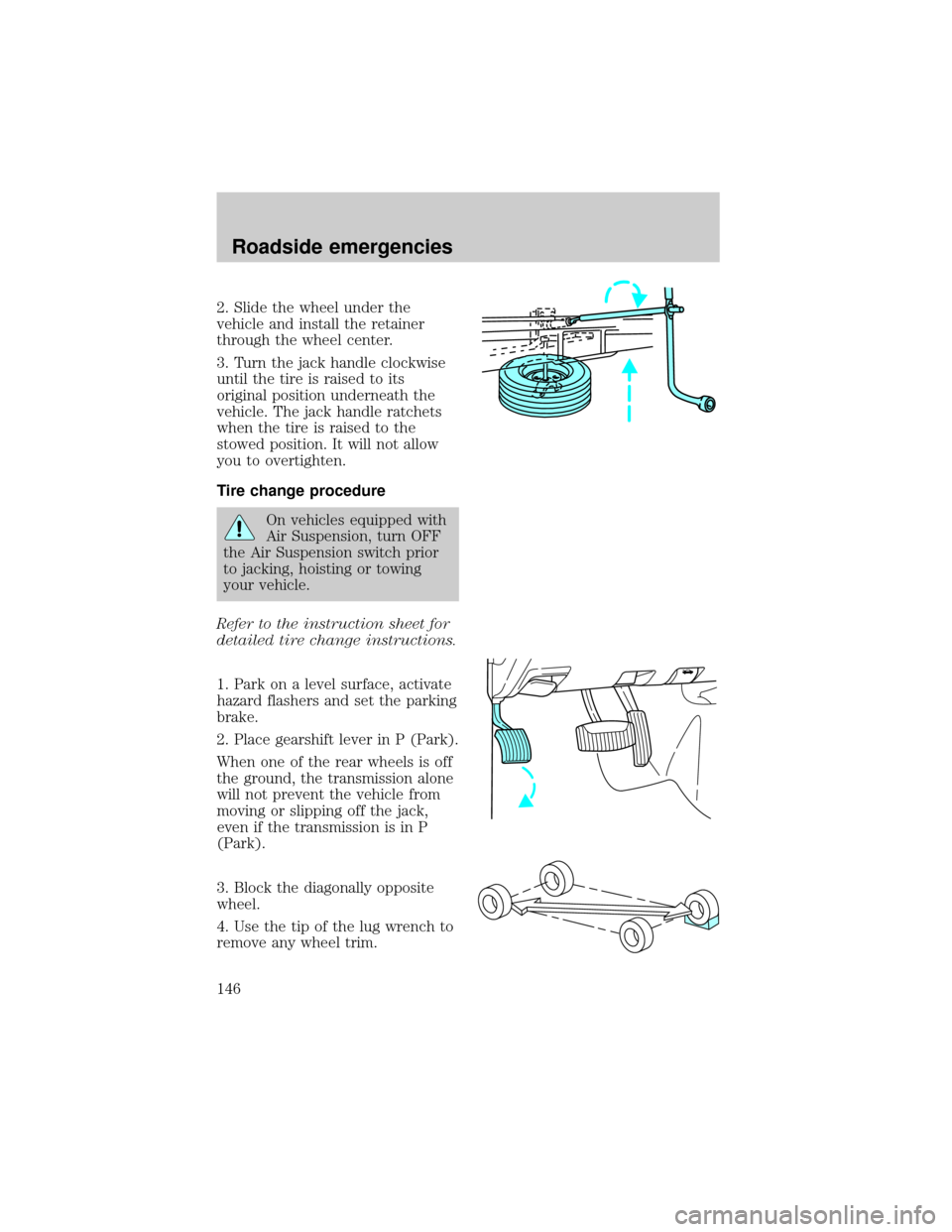
2. Slide the wheel under the
vehicle and install the retainer
through the wheel center.
3. Turn the jack handle clockwise
until the tire is raised to its
original position underneath the
vehicle. The jack handle ratchets
when the tire is raised to the
stowed position. It will not allow
you to overtighten.
Tire change procedure
On vehicles equipped with
Air Suspension, turn OFF
the Air Suspension switch prior
to jacking, hoisting or towing
your vehicle.
Refer to the instruction sheet for
detailed tire change instructions.
1. Park on a level surface, activate
hazard flashers and set the parking
brake.
2. Place gearshift lever in P (Park).
When one of the rear wheels is off
the ground, the transmission alone
will not prevent the vehicle from
moving or slipping off the jack,
even if the transmission is in P
(Park).
3. Block the diagonally opposite
wheel.
4. Use the tip of the lug wrench to
remove any wheel trim.
Roadside emergencies
146
Page 147 of 216

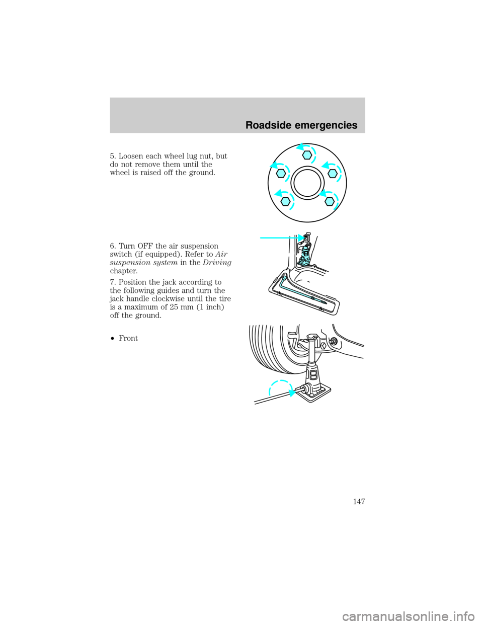
5. Loosen each wheel lug nut, but
do not remove them until the
wheel is raised off the ground.
6. Turn OFF the air suspension
switch (if equipped). Refer toAir
suspension systemin theDriving
chapter.
7. Position the jack according to
the following guides and turn the
jack handle clockwise until the tire
is a maximum of 25 mm (1 inch)
off the ground.
²Front
Roadside emergencies
147
Page 148 of 216

²Rear
²Never use the front or rear
differential as a jacking
point.
8. Remove the lug nuts with the
lug wrench.
9. Replace the flat tire with the
spare tire, making sure the valve
stem is facing outward. Reinstall
the lug nuts, cone side in, until the
wheel is snug against the hub. Do
not fully tighten the lug nuts until
the wheel has been lowered.
10. Lower the wheel by turning the
jack handle counterclockwise.
11. Remove the jack and fully
tighten the lug nuts in the order
shown.
1
4 3
52
Roadside emergencies
148
Page 165 of 216

If sprayed on the windshield,
engine coolant could make it
difficult to see through the
windshield.
When the engine is cool, add a
50/50 mixture of engine coolant
and water to the engine coolant
recovery reservoir-DO NOT ADD
DIRECTLY TO THE RADIATOR.
Add straight water only in an
emergency, but you should replace
it with a 50/50 mixture of coolant
and distilled water as soon as
possible.
Check the coolant level in the
coolant recovery reservoir the next
few times you drive the vehicle. If
necessary, add enough of a 50/50
mixture of coolant and water to
bring the liquid level to the fill line
on the reservoir.
Never remove the coolant
recovery cap while the
engine is running or hot.
If you must remove the coolant
recovery cap, follow these steps to
avoid personal injury:
1. Before you remove the cap, turn
the engine off and let it cool.
2. When the engine is cool, wrap a
thick cloth around the cap. Slowly
turn cap counterclockwise to the
first stop.
3. Step back while the pressure
releases.
4. When you are sure that all the
pressure has been released, use
Maintenance and care
165
Page 166 of 216

the cloth to press the cap down,
turn it counterclockwise and
remove it.
Use Ford Premium Cooling System
Fluid E2FZ-19549±AA (in Canada,
Motorcraft CXC-8±B) or an
equivalent premium engine coolant
that meets Ford specification
ESE-M97B44±A. Ford Premium
Engine Coolant is an optimized
formula that will protect all metals
and rubber elastomers used in
Ford cooling systems for four years
or 80,000 km (50,000 miles).
Do not use alcohol or methanol
antifreeze or any engine coolants
mixed with alcohol or methanol
antifreeze. Do not use
supplemental coolant additives in
your vehicle. These additives may
harm your engine cooling system.
The use of an improper coolant
may void your warranty of your
vehicle's engine cooling system.
Recycled engine coolant
Ford Motor Company recommends
that Ford and Lincoln-Mercury
dealers use recycled engine
coolant produced by
Ford-approved processes. Not all
coolant recycling processes
produce coolant which meets Ford
specification ESE-M97B44±A, and
use of such coolant may harm
engine and cooling system
components.
Always dispose of used
automotive fluids in a responsible
manner. Follow your community's
Maintenance and care
166
Page 175 of 216

²If the battery has been
disconnected or a new battery
has been installed, the clock and
the preset radio stations must
be reset once the battery is
reconnected.
²Always dispose of automotive
batteries in a responsible
manner. Follow your
communities standards for
disposal. Call your local
recycling center to find out
more about recycling automotive
batteries.
WINDSHIELD WIPER BLADES
Check the wiper blades at least
twice a year or when they seem
less effective. Substances such as
tree sap and some hot wax
treatments used by commercial car
washes reduce the effectiveness of
wiper blades.
Checking the wiper blades
If the wiper blades do not wipe
properly, clean both the windshield
and wiper blades using undiluted
windshield wiper solution or a mild
detergent. Rinse thoroughly with
clean water. To avoid damaging the
blades, do not use fuel, kerosene,
paint thinner or other solvents.
Changing the wiper blades
When replacing wiper blade
assemblies, always use a
Motorcraft part or equivalent. To
make replacing the wipers easy,
Maintenance and care
175
Page 192 of 216

3. Disconnect the electrical
connector from the bulb by pulling
the connector rearward.
4. Remove the bulb retaining ring
by rotating it counterclockwise
(when viewed from the rear) about
an eighth of a turn to free it from
the bulb socket, and by sliding the
ring off the plastic base. Keep the
ring because it will be used again
to retain the new bulb.
5. Remove the old bulb from its
socket by gently pulling it straight
back out of the socket. Do not turn
the bulb while removing it.
To install the new bulb:
1. With the flat side of the bulb's
plastic base facing upward, insert
the glass end of the bulb into the
socket. You may need to turn the
bulb left or right to line up the
grooves in the plastic base with
the tabs in the socket. When the
grooves are aligned, push the bulb
into the socket until the plastic
base contacts the rear of the
socket.
2. Slip the bulb retaining ring over
the plastic base until it contacts
the rear of the socket by rotating it
clockwise until you feel a ªstop.º
Maintenance and care
192
Page 195 of 216

Horizontal aim adjustment
1. With the hood open, locate the
horizontal indicator and adjusting
screw. They are located below the
viewing hole at the rear of the
headlamp assembly.
2. Use a 4mm wrench or socket to
turn the horizontal adjusting screw
until the ª0º mark on the yellow
dial lines up with the reference
mark on the marker (as shown)
when viewed directly from above.
Vertical aim adjustment
1. Park the vehicle on a level
surface.
2. With the hood open, locate the
bubble level and vertical
adjustment screw. The adjustment
screw is located on the outboard
side of the headlamp.
3. The ªUPº and ªDNº on the
bubble indicate the directional
change (up or down) of the
vertical aim.
4.Usea4mmwrench or socket to
turn the vertical adjusting screw
clockwise or counterclockwise until
the bubble is centered over the ª0º
mark.
U
D
U
D
Maintenance and care
195