fuse Mercury Mountaineer 1999 Owner's Manuals
[x] Cancel search | Manufacturer: MERCURY, Model Year: 1999, Model line: Mountaineer, Model: Mercury Mountaineer 1999Pages: 248, PDF Size: 1.74 MB
Page 127 of 248
Do not attempt to service, repair, or modify the Air Bag
Supplemental Restraint System or its fuses. See your Ford or
Lincoln-Mercury dealer.
Children and air bags
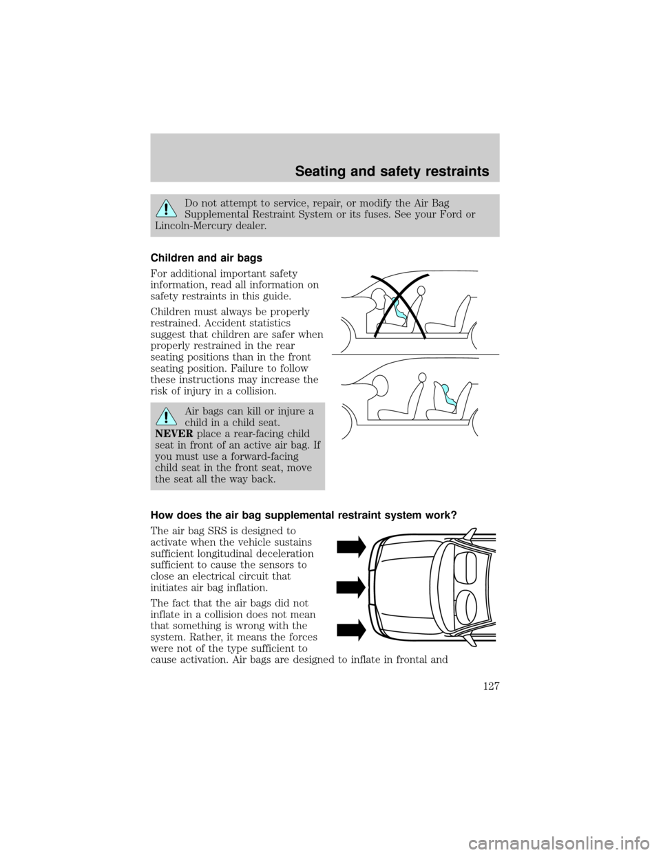
For additional important safety
information, read all information on
safety restraints in this guide.
Children must always be properly
restrained. Accident statistics
suggest that children are safer when
properly restrained in the rear
seating positions than in the front
seating position. Failure to follow
these instructions may increase the
risk of injury in a collision.
Air bags can kill or injure a
child in a child seat.
NEVERplace a rear-facing child
seat in front of an active air bag. If
you must use a forward-facing
child seat in the front seat, move
the seat all the way back.
How does the air bag supplemental restraint system work?
The air bag SRS is designed to
activate when the vehicle sustains
sufficient longitudinal deceleration
sufficient to cause the sensors to
close an electrical circuit that
initiates air bag inflation.
The fact that the air bags did not
inflate in a collision does not mean
that something is wrong with the
system. Rather, it means the forces
were not of the type sufficient to
cause activation. Air bags are designed to inflate in frontal and
Seating and safety restraints
127
Page 129 of 248
²and the electrical wiring which connects the components.
The diagnostic module monitors its own internal circuits and the
supplemental air bag electrical system warning (including the impact
sensors), the system wiring, the air bag system readiness light, the air
bag back up power and the air bag ignitors.
Determining if the system is operational
The SRS uses a readiness light in the instrument cluster or a tone to
indicate the condition of the system. Refer to theAir bag readiness
section in theInstrumentationchapter. Routine maintenance of the air
bag is not required.
A difficulty with the system is indicated by one or more of the following:
²The readiness light will either
flash or stay lit.
²The readiness light will not
illuminate immediately after
ignition is turned on.
²A series of five beeps will be heard. The tone pattern will repeat
periodically until the problem and light are repaired.
If any of these things happen, even intermittently, have the SRS serviced
at your dealership or by a qualified technician immediately. Unless
serviced, the system may not function properly in the event of a
collision.
Side air bag system (if equipped)
Do not use accessory seat covers. The use of accessory seat
covers may prevent the deployment of the side air bags and
increase the risk of injury in an accident.
Do not lean your head on the door, the side air bag could injure
you as it deploys from the side of the seatback.
Do not attempt to service, repair, or modify the air bag
Supplemental Restraint System, its fuses or the seat cover on a
seat containing an air bag. See your Ford or Lincoln Mercury dealer.
Seating and safety restraints
129
Page 146 of 248
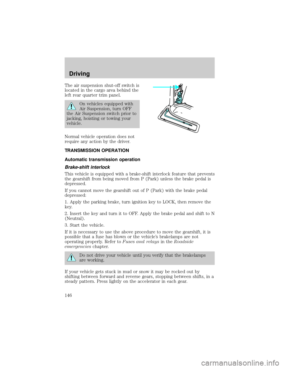
The air suspension shut-off switch is
located in the cargo area behind the
left rear quarter trim panel.
On vehicles equipped with
Air Suspension, turn OFF
the Air Suspension switch prior to
jacking, hoisting or towing your
vehicle.
Normal vehicle operation does not
require any action by the driver.
TRANSMISSION OPERATION
Automatic transmission operation
Brake-shift interlock
This vehicle is equipped with a brake-shift interlock feature that prevents
the gearshift from being moved from P (Park) unless the brake pedal is
depressed.
If you cannot move the gearshift out of P (Park) with the brake pedal
depressed:
1. Apply the parking brake, turn ignition key to LOCK, then remove the
key.
2. Insert the key and turn it to OFF. Apply the brake pedal and shift to N
(Neutral).
3. Start the vehicle.
If it is necessary to use the above procedure to move the gearshift, it is
possible that a fuse has blown or the vehicle's brakelamps are not
operating properly. Refer toFuses and relaysin theRoadside
emergencieschapter.
Do not drive your vehicle until you verify that the brakelamps
are working.
If your vehicle gets stuck in mud or snow it may be rocked out by
shifting between forward and reverse gears, stopping between shifts, in a
steady pattern. Press lightly on the accelerator in each gear.
Driving
146
Page 170 of 248

The fuel pump shut-off switch is
located in the passenger's foot well,
behind the kick panel.
FUSES AND RELAYS
Fuses
If electrical components in the
vehicle are not working, a fuse may
have blown. Blown fuses are
identified by a broken wire within
the fuse. Check the appropriate
fuses before replacing any electrical
components.
Always replace a fuse with one that has the specified amperage
rating. Using a fuse with a higher amperage rating can cause
severe wire damage and could start a fire.
15
Roadside emergencies
170
Page 171 of 248

Standard fuse amperage rating and color
COLOR
Fuse
RatingMini
FusesStandard
FusesMaxi
FusesCartridge
Maxi
FusesFuse Link
Cartridge
2A Grey Grey Ð Ð Ð
3A Violet Violet Ð Ð Ð
4A Pink Pink Ð Ð Ð
5A Tan Tan Ð Ð Ð
7.5A Brown Brown Ð Ð Ð
10A Red Red Ð Ð Ð
15A Blue Blue Ð Ð Ð
20A Yellow Yellow Yellow Blue Blue
25A Natural Natural Ð Ð Ð
30A Green Green Green Pink Pink
40A Ð Ð Orange Green Orange
50A Ð Ð Red Red Red
60A Ð Ð Blue Ð Yellow
70A Ð Ð Tan Ð Brown
80A Ð Ð Natural Ð Black
Roadside emergencies
171
Page 172 of 248

Passenger compartment fuse panel
The fuse panel is located on the left
hand side of the instrument panel
facing the driver's side door. Pull the
panel cover outward to access the
fuses.
To remove a fuse use the fuse puller tool provided on the fuse panel
cover.
1 234
5 678
9 101112
13 14 15 16
17 18 19 20
21 22 23 24
25 26
29 30
35 36
313233
34
27 28
Roadside emergencies
172
Page 173 of 248
The fuses are coded as follows:
Fuse/Relay
LocationFuse Amp
RatingDescription
1 7.5A Power Mirror Switch, Power Antenna
2 7.5A Blower Motor Relay, Air Bag Diagnostic
Monitor
3 7.5A Left Stop/Turn Trailer Tow Connector
4 10A Left Headlamp
5 10A Data Link Connector (DLC)
6 7.5A Rear Blower Motor (Without EATC)
7 7.5A Right Stop/Turn Trailer Tow Connector
8 10A Right Headlamp, Foglamp Relay
9 7.5A Brake Pedal Position Switch
10 7.5A Speed Control/Amplifier Assembly, Generic
Electronic Module (GEM), Shift Lock
Actuator, Blend Door Actuator, A/C - Heater
Assembly, Flasher, Overhead Console, Load
Leveling Module
11 7.5A Instrument Cluster
12 7.5A Washer Pump Relay, Rear Washer Pump
Relay
13 20A Brake Pedal Position Switch, Brake Pressure
Switch
14 10A 4 Wheel Anti-Lock Brake System (4WABS)
Module, 4WABS Main Relay
15 7.5A Instrument Cluster
16 30A Windshield Wiper Motor, Wiper Hi-Lo Relay,
Wiper Run/Park Relay
17 25A Cigar Lighter
18 25A Drivers Unlock Relay, All Unlock Relay, All
Lock Relay
19 25A PCM Power Diode
20 7.5A RAP Module, Generic Electronic Module
(GEM), Radio, Cellular Phone
Roadside emergencies
173
Page 174 of 248

Fuse/Relay
LocationFuse Amp
RatingDescription
21 15A Flasher (Hazard)
22 20A Auxiliary Power Socket
23 Ð Not Used
24 7.5A Clutch Pedal Position (CPP) Switch, Starter
Interrupt Relay, Anti-Theft
25 7.5A Generic Electronic Module (GEM),
Instrument Cluster, Securi-Lock
26 10A Battery Saver Relay, Electronic Shift Relay,
Interior Lamp Relay, Electronic Shift Control
Module
27 15A DRL, Backup Lamps Switch, DTR Sensor
28 7.5A Generic Electronic Module (GEM), Radio,
Memory Seat
29 10A Radio
30 15A Park Lamp/Trailer Tow Relay
31 Ð Not Used
32 10A Heated Mirror
33 15A Headlamps, Daytime Running Lamps (DRL)
Module, Instrument Cluster
34 7.5A Rear Integrated Control Panel, CD
35 7.5A Rear Blower Motor (With EATC)
36 7.5A EATC Memory, CD, Rear Integrated Control
Panel, Memory Seat, Message Center
Roadside emergencies
174
Page 175 of 248

Power distribution box
The power distribution box is
located in the engine compartment.
The power distribution box contains
high-current fuses that protect your
vehicle's main electrical systems
from overloads.
Always disconnect the battery before servicing high current
fuses.
Always replace the cover to the Power Distribution Box before
reconnecting the battery or refilling fluid reservoirs.
Roadside emergencies
175
Page 176 of 248
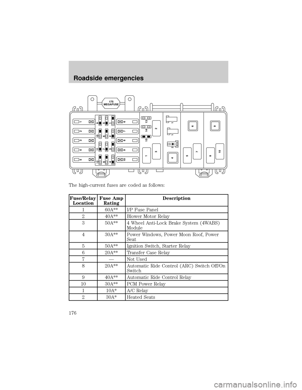
The high-current fuses are coded as follows:
Fuse/Relay
LocationFuse Amp
RatingDescription
1 60A** I/P Fuse Panel
2 40A** Blower Motor Relay
3 50A** 4 Wheel Anti-Lock Brake System (4WABS)
Module
4 30A** Power Windows, Power Moon Roof, Power
Seat
5 50A** Ignition Switch, Starter Relay
6 20A** Transfer Case Relay
7 Ð Not Used
8 20A** Automatic Ride Control (ARC) Switch Off/On
Switch
9 40A** Automatic Ride Control Relay
10 30A** PCM Power Relay
1 10A* A/C Relay
2 30A* Heated Seats
5432110 9 8 7 612 11 10 9
876 5
432 1
14 15 13
211
9 6
10 87 5 41
2 3
175
MEGAFUSE
Roadside emergencies
176