tow Mercury Mountaineer 2001 s User Guide
[x] Cancel search | Manufacturer: MERCURY, Model Year: 2001, Model line: Mountaineer, Model: Mercury Mountaineer 2001Pages: 280, PDF Size: 1.95 MB
Page 102 of 280

1. Remove the shade from the vehicle and extend it with the smooth
grain facing you.
2. Wrap the vinyl around the roller
tube twice. Tuck the edges of the
vinyl inside the end cap with each
wrap.
3. Fold the edges of the vinyl
towards the center, making sure
that the edges clear the end cap
slots. Use tape or a rubber band to
hold the vinyl to the left side of the
tube.
4. Push in the right end cap
(marked RH) about
1¤4of the total
length to disengage the clutch and
hold the end cap in while turning
the roller tube toward you 14 times.
5. Let go of the right end cap. The
clutch will now engage and stop the
shade from losing its spring tension.
6. Unfold the vinyl and place it into
the end cap slots.
7. Insert the shade into the side mounting brackets and check to make
sure that it operates properly.
The cover may cause injury in a sudden stop or accident if it is
not securely installed.
REMOTE ENTRY SYSTEM (IF EQUIPPED)
The remote entry system allows you to lock or unlock all vehicle doors
without a key.
The remote entry features only operate with the ignition in the LOCK
position.
If there is any potential remote keyless entry problem with your vehicle,
ensureALL key fobs(remote entry transmitters) are brought to the
dealership, to aid in troubleshooting.
Controls and features
102
Page 105 of 280

Replacing the battery
The transmitter is powered by one coin type three-volt lithium battery
CR2032 or equivalent. Typical operating range will allow you to be up to
10 meters (33 feet) away from your vehicle. A decrease in operating
range can be caused by:
²weather conditions
²nearby radio towers
²structures around the vehicle
²other vehicles parked next to the vehicle
To replace the battery:
1. Twist a thin coin between the two
halves of the transmitter near the
key ring. DO NOT TAKE THE
FRONT PART OF THE
TRANSMITTER APART.
2. Place the positive (+) side of new
battery in the same orientation.
Refer to the diagram inside the
transmitter unit.
3. Snap the two halves back
together.
Replacing lost transmitters
If a remote transmitter has been lost
and you would like to remove it
from the vehicle's memory, or you
would like to purchase additional
remote transmitters and have them
programmed to your vehicle:
²Takeallyour vehicle's
transmitters to your dealer for
programming, or
²Perform the programming
procedure yourself
Controls and features
105
Page 111 of 280

The SecuriLockypassive anti-theft
system is not compatible with
non-Ford (aftermarket) remote start
systems. Use of these systems may
result in vehicle starting problems and
a loss of security protection. Large
metallic objects, electronic devices on
the key chain that can be used to
purchase gasoline or similar items, or
a second key on the same key ring as
the PATS ignition key may cause
vehicle starting concern. If present,
you need to keep these objects from
touching the PATS ignition key while
starting the engine. These objects and
devices cannot damage the PATS ignition key, but can
cause a momentary concern if they are too close to the key during engine
start. If a problem occurs, turn ignition OFF and restart the engine with all
other objects on the key ring held away from the ignition key. Check to make
sure the encoded ignition key is an approved Ford encoded ignition key.
If your keys are lost or stolen you
will need to do the following:
²Use your spare key to start the
vehicle. or
²Have your vehicle towed to a
dealership or locksmith. The key
codes will need to be erased from
your vehicle and new key codes will need to be re-coded.
Replacing coded keys can be very costly and you may want to store an
extra programmed key away from the vehicle in a safe place to prevent
an unforeseen inconvenience.
The correct PATS key must be used for your vehicle. The use of the
wrong type of PATS key may lead to a ªNO-STARTº condition. Refer to
the Rotunda Key Application Matrix for the correct PATS key type for
your particular vehicle make and model year. If a key Application Marix
is not available, call 1±800±ROTUNDA (1±800±768±8632) (press 2) to
order a Key Application Matrix.
If an unprogrammed key is used in the ignition it will cause a
ªNO STARTºcondition.
Controls and features
111
Page 116 of 280

Using the manual lumbar support (if equipped)
Turn the lumbar support control
toward the front of vehicle to move
the lumbar support forward for
more direct support.
Turn the lumbar support control
toward the rear of vehicle to move
the lumbar support back for less
direct support.
REAR SEATS
Folding rear seats (if equipped)
If the rear seat is equipped with adjustable head restraints, they should
be placed in the full down position before folding the seat back down.
1. Press the lower release control
downward to unlatch the seatback.
2. Rotate the seatback downward
into the load floor position.
3. Press down on the top outboard
area of the seatback until a click is
heard. The seat is now latched in
the floor position.
Seating and safety restraints
116
Page 140 of 280

7. Pull the lap belt portion across
the child seat toward the buckle and
pull up on the shoulder belt while
pushing down with your knee on the
child seat.
8. Allow the safety belt to retract to
remove any slack in the belt.
9. Before placing the child in the
seat, forcibly tilt the seat forward
and back to make sure the seat is
securely held in place.
10. Try to pull the belt out of the retractor to make sure the retractor is
in the automatic locking mode (you should not be able to pull more belt
out). If the retractor is not locked, unbuckle the belt and repeat steps
two through nine.
Check to make sure the child seat is properly secured before each use.
Attaching child safety seats with tether straps
Most new forward-facing child safety seats include a tether strap which
goes over the back of the seat and hooks to an anchoring point. Tether
straps are available as an accessory for many older safety seats. Contact
the manufacturer of your child seat for information about ordering a
tether strap.
Seating and safety restraints
140
Page 152 of 280

The air suspension shut-off switch is
located in the cargo area behind the
left rear quarter trim panel.
On vehicles equipped with
Air Suspension, turn OFF
the Air Suspension switch prior to
jacking, hoisting or towing your
vehicle.
Normal vehicle operation does not
require any action by the driver.
PREPARING TO DRIVE YOUR VEHICLE
Utility vehicles have a significantly higher rollover rate than
other types of vehicles.
In a rollover crash, an unbelted person is significantly more likely
to die than a person wearing a seat belt.
Your vehicle has special design and equipment features to make it
capable of performing in a wide variety of circumstances. These special
design features, such as larger tires and increased ground clearance, give
the vehicle a higher center of gravity than a passenger car.
Vehicles with a higher center of gravity such as utility and
four-wheel drive vehicles handle differently than vehicles with a
lower center of gravity. Utility and four-wheel drive vehicles arenot
designed for cornering at speeds as high as passenger cars any more
than low-slung sports cars are designed to perform satisfactorily under
off-road conditions. Avoid sharp turns, excessive speed and abrupt
maneuvers in these vehicles. Failure to drive cautiously could result in
an increased risk of vehicle rollover, personal injury and death.
Loaded vehicles, with a higher center of gravity, may handle
differently than unloaded vehicles. Extra precautions, such as
slower speeds and increased stopping distance, should be taken when
driving a heavily loaded vehicle.
Driving
152
Page 155 of 280

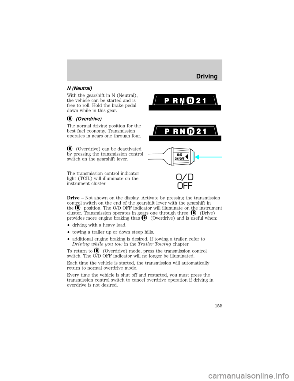
N (Neutral)
With the gearshift in N (Neutral),
the vehicle can be started and is
free to roll. Hold the brake pedal
down while in this gear.
(Overdrive)
The normal driving position for the
best fuel economy. Transmission
operates in gears one through four.
(Overdrive) can be deactivated
by pressing the transmission control
switch on the gearshift lever.
The transmission control indicator
light (TCIL) will illuminate on the
instrument cluster.
Drive± Not shown on the display. Activate by pressing the transmission
control switch on the end of the gearshift lever with the gearshift in
the
position. The O/D OFF indicator will illuminate on the instrument
cluster. Transmission operates in gears one through three.
(Drive)
provides more engine braking than
(Overdrive) and is useful when:
²driving with a heavy load.
²towing a trailer up or down steep hills.
²additional engine braking is desired. If towing a trailer, refer to
Driving while you towin theTrailer Towingchapter.
To return to
(Overdrive) mode, press the transmission control
switch. The O/D OFF indicator will no longer be illuminated.
Each time the vehicle is started, the transmission will automatically
return to normal overdrive mode.
Every time the vehicle is shut off and restarted, you must press the
transmission control switch to cancel overdrive operation if driving in
overdrive is not desired.
O/D
ON/OFF
O/ D
OFF
Driving
155
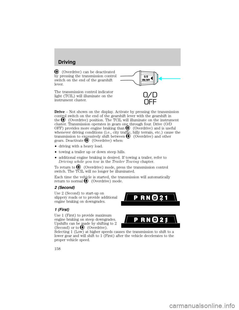
Page 158 of 280

(Overdrive) can be deactivated
by pressing the transmission control
switch on the end of the gearshift
lever.
The transmission control indicator
light (TCIL) will illuminate on the
instrument cluster.
Drive± Not shown on the display. Activate by pressing the transmission
control switch on the end of the gearshift lever with the gearshift in
the
(Overdrive) position. The TCIL will illuminate on the instrument
cluster. Transmission operates in gears one through four. Drive (O/D
OFF) provides more engine braking than
(Overdrive) and is useful
whenever driving conditions (i.e., city traffic, hilly terrain, etc.) cause the
transmission to excessively shift between
(Overdrive) and other
gears. Deactivate
(Overdrive) when:
²driving with a heavy load.
²towing a trailer up or down steep hills.
²additional engine braking is desired. If towing a trailer, refer to
Driving while you towin theTrailer Towingchapter.
To return to
(Overdrive) mode, press the transmission control
switch. The TCIL will no longer be illuminated.
Each time the vehicle is started, the transmission will automatically
return to normal
(Overdrive) mode.
2 (Second)
Use 2 (Second) to start-up on
slippery roads or to provide additional
engine braking on downgrades.
1 (First)
Use 1 (First) to provide maximum
engine braking on steep downgrades.
Upshifts can be made by shifting to 2
(Second) or to
(Overdrive).
Selecting 1 (Low) at higher speeds causes the transmission to shift to a
lower gear and will shift to 1 (First) after the vehicle decelerates to the
proper vehicle speed.
O/D
ON/OFF
O/ D
OFF
Driving
158
Page 168 of 280

²GVWR (Gross Vehicle Weight Rating):Maximum total weight of
the base vehicle, passengers, optional equipment and cargo. The
GVWR is specific to each vehicle and is listed on the Safety
Certification Label on the driver's door pillar.
²GAWR (Gross Axle Weight Rating):Carrying capacity for each axle
system. The GAWR is specific to each vehicle and is listed on the
Safety Certification Label on the driver's door pillar.
²GCW (Gross Combined Weight):The combined weight of the
towing vehicle (including passengers and cargo) and the trailer.
²GCWR (Gross Combined Weight Rating):Maximum combined
weight of towing vehicle (including passengers and cargo) and the
trailer. The GCWR indicates the maximum loaded weight that the
vehicle is designed to tow.
²Maximum Trailer Weight Rating:Maximum weight of a trailer the
vehicle is permitted to tow. The maximum trailer weight rating is
determined by subtracting the vehicle curb weight for each
engine/transmission combination, any required option weight for trailer
towing and the weight of the driver from the GCWR for the towing
vehicle.
²Maximum Trailer Weight:Maximum weight of a trailer the loaded
vehicle (including passengers and cargo) is permitted to tow. It is
determined by subtracting the weight of the loaded trailer towing
vehicle from the GCWR for the towing vehicle.
²Trailer Weight Range:Specified weight range that the trailer must
fall within that ranges from zero to the maximum trailer weight rating.
Remember to figure in the tongue load of your loaded trailer when
figuring the total weight.
Do not exceed the GVWR or the GAWR specified on the
certification label.
Do not use replacement tires with lower load carrying capacities than the
originals because they may lower the vehicle's GVWR and GAWR
limitations. Replacement tires with a higher limit than the originals do
not increase the GVWR and GAWR limitations.
The Safety Certification Label, found on the driver's door pillar, lists
several important vehicle weight rating limitations. Before adding any
additional equipment, refer to these limitations. If you are adding weight
Driving
168
Page 169 of 280

to the front of your vehicle, (potentially including weight added to the
cab), the weight added should not exceed the front axle reserve capacity
(FARC). Additional frontal weight may be added to the front axle reserve
capacity provided you limit your payload in other ways (i.e. restrict the
number of passengers or amount of cargo carried).
Always ensure that the weight of passengers, cargo and equipment being
carried is within the weight limitations that have been established for
your vehicle including both gross vehicle weight and Front and rear
gross axle weight rating limits. Under no circumstance should these
limitations be exceeded. Exceeding any vehicle weight rating limitation
could result in serious damage to the vehicle and/or personal injury.
Special loading instructions for owners of pickup trucks and
utility-type vehicles
For important information regarding safe operation of this type
of vehicle, see thePreparing to drive your vehiclesection in
theDrivingchapter of this owner guide.
Loaded vehicles, with a higher center of gravity, may handle
differently than unloaded vehicles. Extra precautions, such as
slower speeds and increased stopping distance, should be taken when
driving a heavily loaded vehicle.
Your vehicle has the capability to haul more cargo and people than most
passenger cars. Depending upon the type and placement of the load,
hauling cargo and people may raise the center of gravity of the vehicle.
Calculating the load your vehicle can carry/tow
1. Use the appropriate maximum gross combined weight rating (GCWR)
chart to find the maximum GCWR for your type engine and rear axle
ratio.
2. Weigh your vehicle as you customarily operate the vehicle without
cargo. To obtain correct weights, try taking your vehicle to a shipping
company or an inspection station for trucks.
3. Subtract your loaded vehicle weight from the maximum GCWR on the
following charts. This is the maximum trailer weight your vehicle can tow
and must fall below the maximum shown under maximum trailer weight
on the chart.
Driving
169