mirror controls Mercury Mountaineer 2005 Owner's Manuals
[x] Cancel search | Manufacturer: MERCURY, Model Year: 2005, Model line: Mountaineer, Model: Mercury Mountaineer 2005Pages: 304, PDF Size: 4.34 MB
Page 1 of 304
Introduction 4
Instrument Cluster 10
Warning and control lights 10
Gauges 14
Entertainment Systems 18
AM/FM stereo with CD 18
AM/FM stereo with in-dash six CD 21
Climate Controls 37
Manual heating and air conditioning 37
Automatic temperature control 39
Auxiliary passenger climate control 42
Rear window defroster 43
Lights 44
Driver Controls 55
Windshield wiper/washer control 55
Steering wheel adjustment 56
Power windows 61
Mirrors 62
Speed control 64
Message center 75
Locks and Security 92
Keys 92
Locks 92
Anti-theft system 94
Seating and Safety Restraints 105
Seating 105
Safety restraints 117
Airbags 130
Child restraints 138
Table of Contents
1
2005 Mountaineer(mnt)
Owners Guide (post-2002-fmt)
USA(fus)
Page 60 of 304
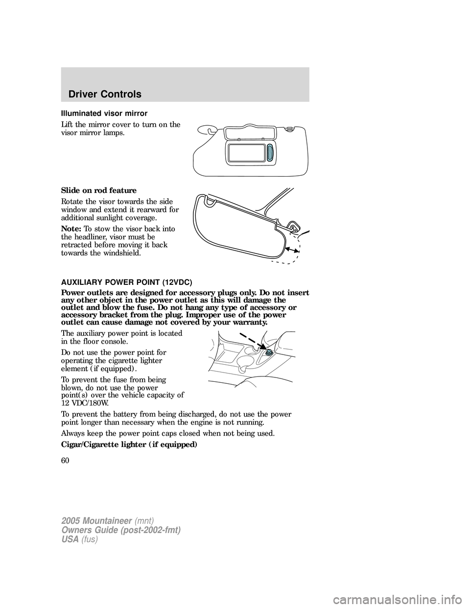
Illuminated visor mirror
Lift the mirror cover to turn on the
visor mirror lamps.
Slide on rod feature
Rotate the visor towards the side
window and extend it rearward for
additional sunlight coverage.
Note:To stow the visor back into
the headliner, visor must be
retracted before moving it back
towards the windshield.
AUXILIARY POWER POINT (12VDC)
Power outlets are designed for accessory plugs only. Do not insert
any other object in the power outlet as this will damage the
outlet and blow the fuse. Do not hang any type of accessory or
accessory bracket from the plug. Improper use of the power
outlet can cause damage not covered by your warranty.
The auxiliary power point is located
in the floor console.
Do not use the power point for
operating the cigarette lighter
element (if equipped).
To prevent the fuse from being
blown, do not use the power
point(s) over the vehicle capacity of
12 VDC/180W.
To prevent the battery from being discharged, do not use the power
point longer than necessary when the engine is not running.
Always keep the power point caps closed when not being used.
Cigar/Cigarette lighter (if equipped)
2005 Mountaineer(mnt)
Owners Guide (post-2002-fmt)
USA(fus)
Driver Controls
60
Page 62 of 304
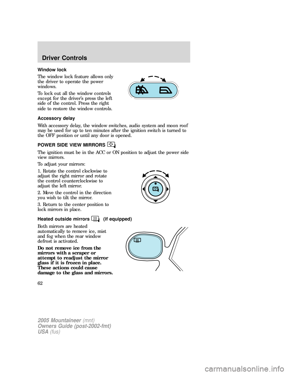
Window lock
The window lock feature allows only
the driver to operate the power
windows.
To lock out all the window controls
except for the driver’s press the left
side of the control. Press the right
side to restore the window controls.
Accessory delay
With accessory delay, the window switches, audio system and moon roof
may be used for up to ten minutes after the ignition switch is turned to
the OFF position or until any door is opened.
POWER SIDE VIEW MIRRORS
The ignition must be in the ACC or ON position to adjust the power side
view mirrors.
To adjust your mirrors:
1. Rotate the control clockwise to
adjust the right mirror and rotate
the control counterclockwise to
adjust the left mirror.
2. Move the control in the direction
you wish to tilt the mirror.
3. Return to the center position to
lock mirrors in place.
Heated outside mirrors
(if equipped)
Both mirrors are heated
automatically to remove ice, mist
and fog when the rear window
defrost is activated.
Do not remove ice from the
mirrors with a scraper or
attempt to readjust the mirror
glass if it is frozen in place.
These actions could cause
damage to the glass and mirrors.
2005 Mountaineer(mnt)
Owners Guide (post-2002-fmt)
USA(fus)
Driver Controls
62
Page 63 of 304
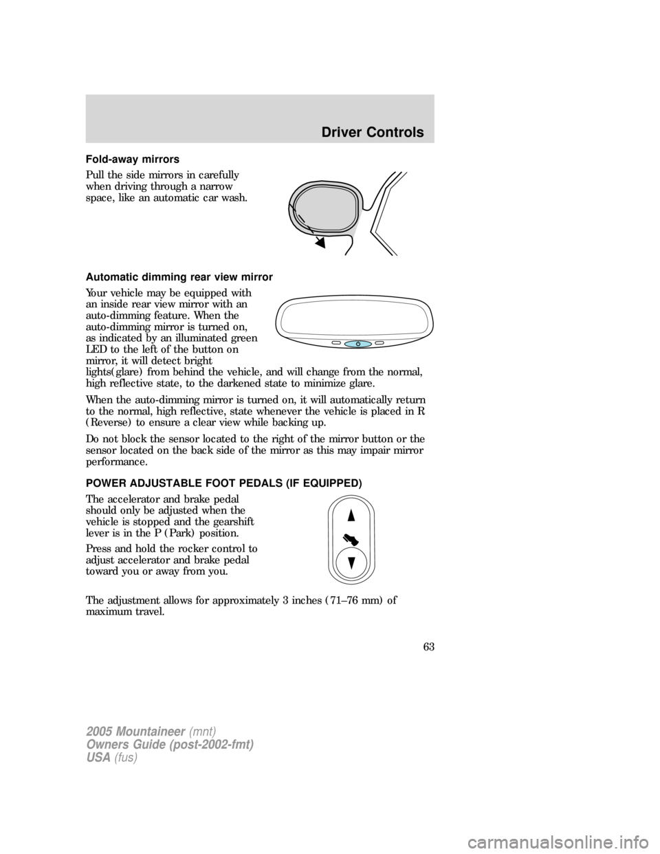
Fold-away mirrors
Pull the side mirrors in carefully
when driving through a narrow
space, like an automatic car wash.
Automatic dimming rear view mirror
Your vehicle may be equipped with
an inside rear view mirror with an
auto-dimming feature. When the
auto-dimming mirror is turned on,
as indicated by an illuminated green
LED to the left of the button on
mirror, it will detect bright
lights(glare) from behind the vehicle, and will change from the normal,
high reflective state, to the darkened state to minimize glare.
When the auto-dimming mirror is turned on, it will automatically return
to the normal, high reflective, state whenever the vehicle is placed in R
(Reverse) to ensure a clear view while backing up.
Do not block the sensor located to the right of the mirror button or the
sensor located on the back side of the mirror as this may impair mirror
performance.
POWER ADJUSTABLE FOOT PEDALS (IF EQUIPPED)
The accelerator and brake pedal
should only be adjusted when the
vehicle is stopped and the gearshift
lever is in the P (Park) position.
Press and hold the rocker control to
adjust accelerator and brake pedal
toward you or away from you.
The adjustment allows for approximately 3 inches (71–76 mm) of
maximum travel.
2005 Mountaineer(mnt)
Owners Guide (post-2002-fmt)
USA(fus)
Driver Controls
63
Page 74 of 304
Compass
The compass reading may be affected when you drive near large
buildings, bridges, power lines and powerful broadcast antennas.
Magnetic or metallic objects placed in, on or near the vehicle may also
affect compass accuracy.
Usually, when something affects the compass readings, the compass will
correct itself after a few days of operating your vehicle in normal
conditions. If the compass still appears to be inaccurate, a manual
calibration may be necessary. Refer toCompass calibration adjustment
in this section.
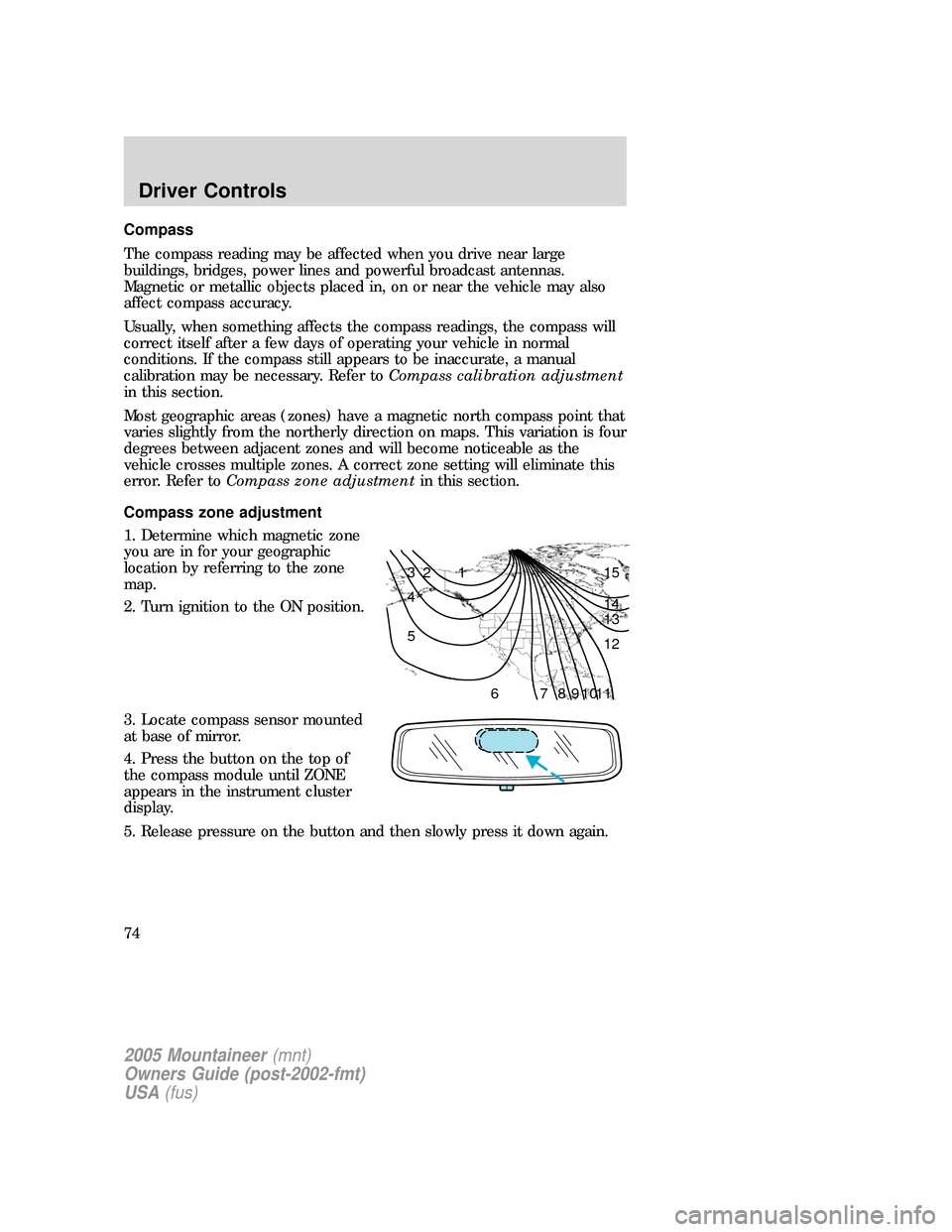
Most geographic areas (zones) have a magnetic north compass point that
varies slightly from the northerly direction on maps. This variation is four
degrees between adjacent zones and will become noticeable as the
vehicle crosses multiple zones. A correct zone setting will eliminate this
error. Refer toCompass zone adjustmentin this section.
Compass zone adjustment
1. Determine which magnetic zone
you are in for your geographic
location by referring to the zone
map.
2. Turn ignition to the ON position.
3. Locate compass sensor mounted
at base of mirror.
4. Press the button on the top of
the compass module until ZONE
appears in the instrument cluster
display.
5. Release pressure on the button and then slowly press it down again.
1 2 3
4
5
6 7 8 9 101112 13 14 15
2005 Mountaineer(mnt)
Owners Guide (post-2002-fmt)
USA(fus)
Driver Controls
74
Page 75 of 304
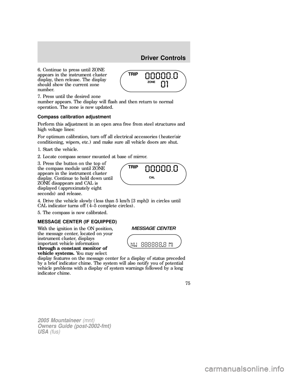
6. Continue to press until ZONE
appears in the instrument cluster
display, then release. The display
should show the current zone
number.
7. Press until the desired zone
number appears. The display will flash and then return to normal
operation. The zone is now updated.
Compass calibration adjustment
Perform this adjustment in an open area free from steel structures and
high voltage lines:
For optimum calibration, turn off all electrical accessories (heater/air
conditioning, wipers, etc.) and make sure all vehicle doors are shut.
1. Start the vehicle.
2. Locate compass sensor mounted at base of mirror.
3. Press the button on the top of
the compass module until ZONE
appears in the instrument cluster
display. Continue to hold down until
ZONE disappears and CAL is
displayed (approximately eight
seconds) and release.
4. Drive the vehicle slowly (less than 5 km/h [3 mph]) in circles until
CAL indicator turns off (4–5 complete circles).
5. The compass is now calibrated.
MESSAGE CENTER (IF EQUIPPED)
With the ignition in the ON position,
the message center, located on your
instrument cluster, displays
important vehicle information
through a constant monitor of
vehicle systems.You may select
display features on the message center for a display of status preceded
by a brief indicator chime. The system will also notify you of potential
vehicle problems with a display of system warnings followed by a long
indicator chime.
2005 Mountaineer(mnt)
Owners Guide (post-2002-fmt)
USA(fus)
Driver Controls
75
Page 302 of 304
Pedals (see Power
adjustable foot pedals) ...............63
Power adjustable foot pedals .....63
Power distribution box
(see Fuses) ...............................227
Power door locks ........................92
Power mirrors .............................62
Power point ...........................60–61
Power steering ..........................204
fluid, checking and adding ....282
fluid, refill capacity ................287
fluid, specifications .........290, 292
Power Windows ...........................61
Preparing to drive your
vehicle ........................................204
R
Radio ..........................18, 21, 25, 30
Rear window defroster ...............43
Relays ................................221, 230
Remote entry system .................94
illuminated entry ......................98
opening the trunk .....................95
Reverse sensing system ...........209
Roadside assistance ..................219
Roof rack .....................................90
S
Safety Belt Maintenance ..........130
Safety belts (see Safety
restraints) ..........117, 119–123, 125
Safety Canopy ...................135–136
Safety defects, reporting ..........246
Safety restraints ........117, 119–125belt minder .............................126
extension assembly ................125
for adults .........................120–123
for children .....................138–139
safety belt maintenance .........130
warning light and
chime ...............................125–126
Safety seats for children ..........141
Safety Compliance
Certification Label ....................294
Seat belts
(see Safety restraints) .............117
Seats ..........................................105
child safety seats ....................141
front seats ...............................106
heated ......................................110
memory seat .....................95, 109
Setting the clock
AM/FM/CD .................................18
AM/FM/In-dash 6 CD ....23, 27, 32
Snowplowing .................................7
Spark plugs, specifications ......286,
292
Special notice
ambulance conversions ..............7
utility-type vehicles ....................7
Specification chart,
lubricants ...........................290, 292
Speed control ..............................64
Starting a flex fuel vehicle .......197
Starting your vehicle ........195, 197
jump starting ..........................231
Steering wheel
controls ......................................66
tilting .........................................56
T
Tilt steering wheel ......................56
Index
302