light Mercury Mystique 1998 s Owner's Guide
[x] Cancel search | Manufacturer: MERCURY, Model Year: 1998, Model line: Mystique, Model: Mercury Mystique 1998Pages: 196, PDF Size: 1.65 MB
Page 91 of 196

Driving
91
TRACTION
CONTROLO/D
OFF
•D (Drive)
D (Drive) provides more engine
braking than overdrive and is
useful when driving through hilly
terrain or if your vehicle requires
additional power for climbing hills.
Activate by pressing the transaxle
control switch (TCS) located on
the gearshift handle. The O/DOFF
indicator light will illuminate in the
instrument cluster. Transaxle
operates in gears one through
three.
To return to overdrive mode, press
the transaxle control switch.The
O/DOFF indicator light will
extinguish.
When starting your vehicle, the
transaxle will automatically return
to normal overdrive mode when the
D (Drive) gearshift position is
selected.
CDW IVB1-10Driving en MM 5/15/97 7:51 PM Page 91
Page 103 of 196

Driving
103 Using a hitch
Do not use hitches that:
•Clamp onto the vehicle bumper.
•Attach to the axle.
Distribute the load so that only 10
to 15% of the total weight of the
trailer is on the tongue. Tie down
the load so that it does not shift
and change weight on the hitch.
Follow the instructions of a
reputable rental agency.
Using trailer lamps
See your local trailer retailer or
rental agency for proper
instructions and equipment for
hooking up trailer lamps.
Do not hook the trailer lamps
directly into the vehicle’s wiring
system. If the trailer lamps are not
working properly, the warning
lights in the instrument cluster may
not work properly.
CDW IVB1-10Driving en MM 5/15/97 7:51 PM Page 103
Page 107 of 196

Roadside emergencies
107 HAZARD FLASHER CONTROL
Use only in an emergency to warn
traffic of vehicle breakdown or
approaching danger. Depress to
activate. Depress again to switch
off. The hazard lights can be
operated when the ignition is off.
Off
ResSet
AccCoast
On
FUELPUMPSHUT-OFF SWITCH
If the engine cranks, but does not
start or does not start after a
collision, the fuel pump shut-off
switch may have been activated.
The shut-off switch is a device
intended to stop the electric fuel
pump when your vehicle has been
involved in a substantial jolt.
Once the shut-off switch is
activated, you must reset the
switch by hand before you can start
your vehicle. The switch is located
on the side panel in front of the
driver’s side door.
CDW IVC1-6Roads en MM 5/15/97 7:53 PM Page 107
Page 111 of 196

Roadside emergencies
111 Ampere
rating
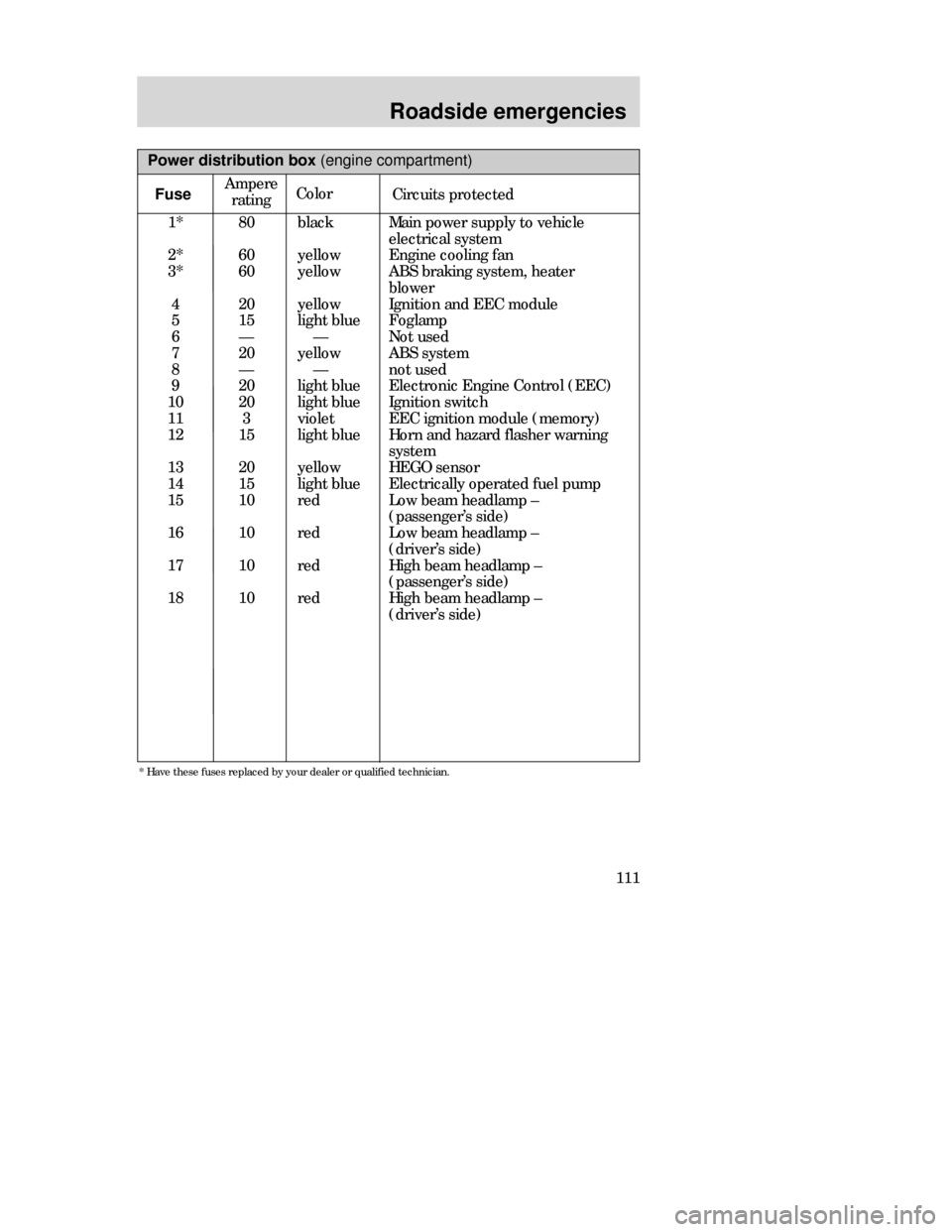
Power distribution box (engine compartment)
Color
Circuits protected
1*
2*
3*
4
5
6
7
8
9
10
11
12
13
14
15
16
17
1880
60
60
20
15
—
20
—
20
20
3
15
20
15
10
10
10
10black
yellow
yellow
yellow
light blue
—
yellow
—
light blue
light blue
violet
light blue
yellow
light blue
red
red
red
redMain power supply to vehicle
electrical system
Engine cooling fan
ABS braking system, heater
blower
Ignition and EEC module
Foglamp
Not used
ABS system
not used
Electronic Engine Control (EEC)
Ignition switch
EEC ignition module (memory)
Horn and hazard flasher warning
system
HEGO sensor
Electrically operated fuel pump
Low beam headlamp –
(passenger’s side)
Low beam headlamp –
(driver’s side)
High beam headlamp –
(passenger’s side)
High beam headlamp –
(driver’s side)
* Have these fuses replaced by your dealer or qualified technician.
Fuse
CDW IVC1-6Roads en MM 5/15/97 7:53 PM Page 111
Page 112 of 196

Roadside emergencies
112Passenger compartment fuse
panel
To check or change a fuse or a
relay, open the fuse box by pulling
down the lock release lever (1).
1
Power distribution box (engine compartment)
Relay
Circuits switched
R 1
R 2
R 3
R 4
R 5
R 6
R 7
R 8
R 9
R 10
R 11
D1
Daytime running lights
Radiator fan relay (high speed)
Air conditioning
Air conditioning clutch relay
Radiator fan relay (low speed)
Starter solenoid
Horn
Electrically operated fuel pump
Low beam headlamps
High beam headlamps
EEC module
Reverse voltage protection
CDW IVC1-6Roads en MM 5/15/97 7:53 PM Page 112
Page 113 of 196

Roadside emergencies
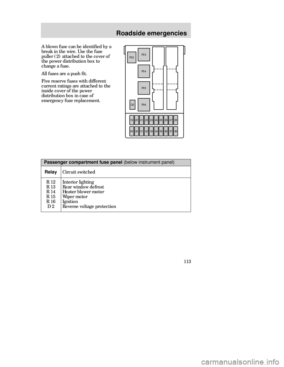
113 A blown fuse can be identified by a
break in the wire. Use the fuse
puller (2) attached to the cover of
the power distribution box to
change a fuse.
All fuses are a push fit.
Five reserve fuses with different
current ratings are attached to the
inside cover of the power
distribution box in case of
emergency fuse replacement.
192021R16 R15
R14 R12R13
22232425262728
29303132333435363738
D2
Passenger compartment fuse panel (below instrument panel)
Relay
Circuit switched
R 12
R 13
R 14
R 15
R 16
D 2Interior lighting
Rear window defrost
Heater blower motor
Wiper motor
Ignition
Reverse voltage protection
CDW IVC1-6Roads en MM 5/15/97 7:53 PM Page 113
Page 114 of 196

Roadside emergencies
114
Passenger compartment fuse panel (below instrument panel)
FuseAmpere
ratingColorCircuits protected
19
20
21
22
23
24
25
26
27
28
29
30
31
32
33
34
35
36
37
38—
C10
40
7.5
15
15
20
7.5
15
30
30
7.5
7.5
7.5
7.5
7.5
7.5
10
30
——
black
orange
brown
light blue
light blue
yellow
brown
light blue
light green
light green
brown
brown
brown
brown
brown
brown
red
light green
–Not used
Wiper motors (circuit breaker)
Power windows
ABS module
Backup lamps
Brake lamps
Door locks
Main light
Cigar lighter
Electric seats
Rear window defrost
Engine management system
Instrument panel illumination
Radio
Parking lamps - driver’s side
Interior lighting/electric mirror
adjustment/clock
Parking lamps - passenger’s side
Air bag
Heater blower motor
Not used
CDW IVC1-6Roads en MM 5/15/97 7:53 PM Page 114
Page 115 of 196

Roadside emergencies
115
Fuse rating
7.5 amp
10 amp
15 amp
20 amp
30 amp
30 amp fuse link
40 amp
60 amp fuse link
80 amp fuse link
100 amp fuse linkColor
brown
red
blue
yellow
light green
pink
green
yellow
black
blue
Relay
R 18
R 20
R 21
R 22
R 23
R 24
R 25
R 26
“One touch” switch
(driver’s window)
Not used
Not used
Foglamps
Turn signals
Panic alarm –
driver’s side
Panic alarm –
right-hand side
Not usedDriver’s door
—
—
Module bracket
Steering column
Door lock module bracket
Door lock module bracket
—
Circuits switchedLocation Standard fuse amperage ratings
and colors
3 ampviolet
Auxiliary relays (outside of fuse boxes)
CDW IVC1-6Roads en MM 5/15/97 7:53 PM Page 115
Page 116 of 196

Roadside emergencies
116
CHANGING TIRES
Park your vehicle in such a position
that neither the traffic nor you are
hindered or endangered when
changing the tire. Ensure that the
vehicle is on firm, level ground. If
necessary, secure your vehicle
further by blocking the wheels with
chocks.
Activate the hazard lights.
Apply the parking brake and
engage first or reverse gear or, if
the vehicle has an automatic
transaxle, select the P (Park)
position.
If parking on a slope is unavoidable,
secure the wheels with suitable
chocks.
CDW IVC1-6Roads en MM 5/15/97 7:53 PM Page 116
Page 119 of 196

Roadside emergencies
119
Removing a tire
1. Apply the parking brake and 1
(first) gear (manual transaxle) or
the P (Park) position (automatic
transaxle).
2. Activate the hazard flashers.
3. The driver and all passengers
must leave the vehicle.
4. Secure the vehicle against rolling
or sliding.
5. Insert the tapered end of the
jack handle between the rim and
hub cover and push in. Twist off to
remove the cover.
6. Loosen the wheel nuts slightly. Tire changing procedure
7. Place jack with complete support
surface on the ground.
8. The jack must be applied exactly
vertical to the jacking point of the
vehicle.
9. Jack up the vehicle until the tire
is clear of the ground. Unscrew and
remove the wheel nuts and remove
the wheel.
CDW IVC1-6Roads en MM 5/15/97 7:53 PM Page 119