engine Mercury Mystique 1998 s Service Manual
[x] Cancel search | Manufacturer: MERCURY, Model Year: 1998, Model line: Mystique, Model: Mercury Mystique 1998Pages: 196, PDF Size: 1.65 MB
Page 112 of 196

Roadside emergencies
112Passenger compartment fuse
panel
To check or change a fuse or a
relay, open the fuse box by pulling
down the lock release lever (1).
1
Power distribution box (engine compartment)
Relay
Circuits switched
R 1
R 2
R 3
R 4
R 5
R 6
R 7
R 8
R 9
R 10
R 11
D1
Daytime running lights
Radiator fan relay (high speed)
Air conditioning
Air conditioning clutch relay
Radiator fan relay (low speed)
Starter solenoid
Horn
Electrically operated fuel pump
Low beam headlamps
High beam headlamps
EEC module
Reverse voltage protection
CDW IVC1-6Roads en MM 5/15/97 7:53 PM Page 112
Page 114 of 196

Roadside emergencies
114
Passenger compartment fuse panel (below instrument panel)
FuseAmpere
ratingColorCircuits protected
19
20
21
22
23
24
25
26
27
28
29
30
31
32
33
34
35
36
37
38—
C10
40
7.5
15
15
20
7.5
15
30
30
7.5
7.5
7.5
7.5
7.5
7.5
10
30
——
black
orange
brown
light blue
light blue
yellow
brown
light blue
light green
light green
brown
brown
brown
brown
brown
brown
red
light green
–Not used
Wiper motors (circuit breaker)
Power windows
ABS module
Backup lamps
Brake lamps
Door locks
Main light
Cigar lighter
Electric seats
Rear window defrost
Engine management system
Instrument panel illumination
Radio
Parking lamps - driver’s side
Interior lighting/electric mirror
adjustment/clock
Parking lamps - passenger’s side
Air bag
Heater blower motor
Not used
CDW IVC1-6Roads en MM 5/15/97 7:53 PM Page 114
Page 122 of 196
Roadside emergencies
122Connecting jumper cables
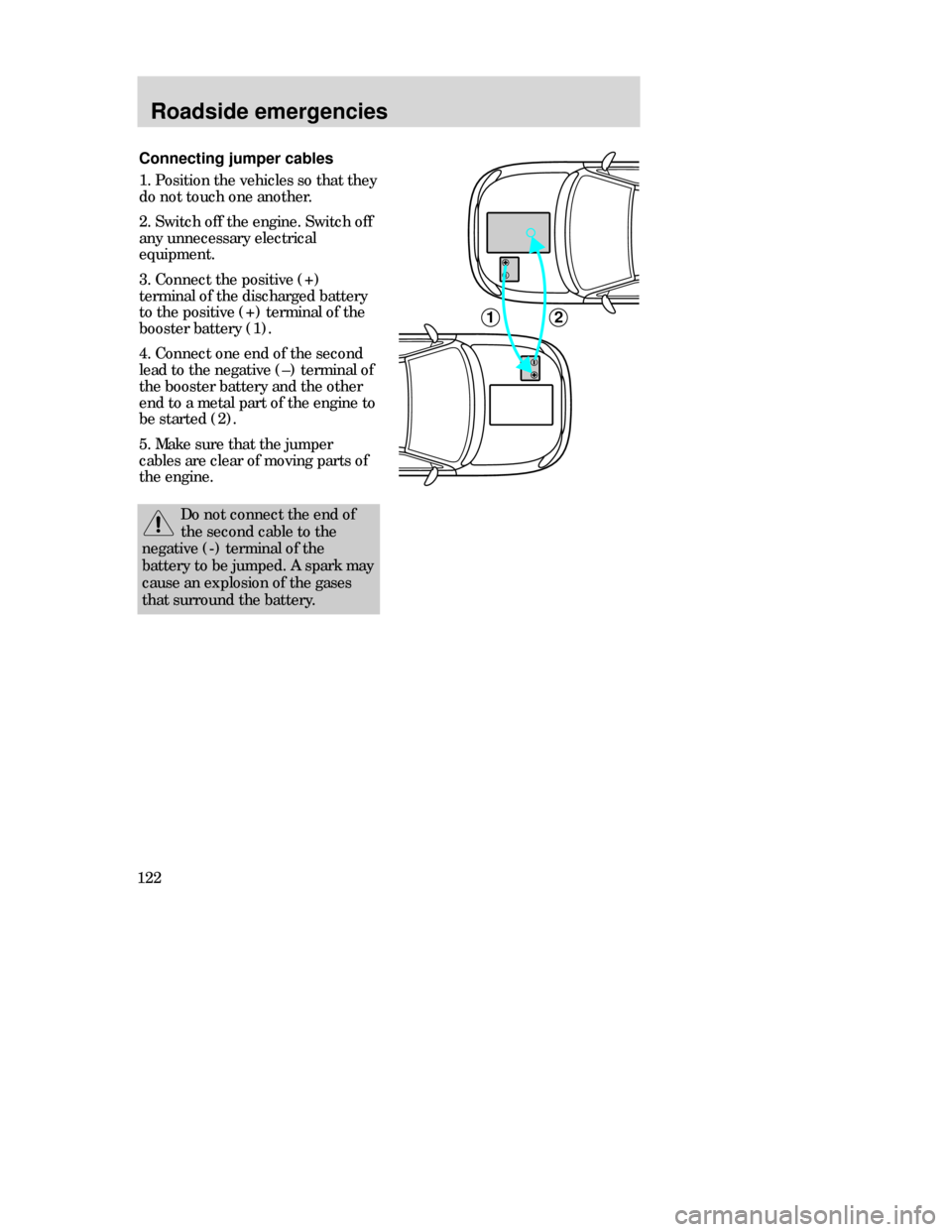
1. Position the vehicles so that they
do not touch one another.
2. Switch off the engine. Switch off
any unnecessary electrical
equipment.
3. Connect the positive (+)
terminal of the discharged battery
to the positive (+) terminal of the
booster battery (1).
4. Connect one end of the second
lead to the negative (–) terminal of
the booster battery and the other
end to a metal part of the engine to
be started (2).
5. Make sure that the jumper
cables are clear of moving parts of
the engine.
12
Do not connect the end of
the second cable to the
negative (-) terminal of the
battery to be jumped. A spark may
cause an explosion of the gases
that surround the battery.
CDW IVC1-6Roads en MM 5/15/97 7:53 PM Page 122
Page 123 of 196
Roadside emergencies
123 Jump starting
1. Start the booster vehicle and run
the engine at moderately increased
speed.
2. Start the engine of the vehicle
with the discharged battery.
3. Once the engine has been
started, run both vehicles for an
additional three minutes before
disconnecting the cable leads.
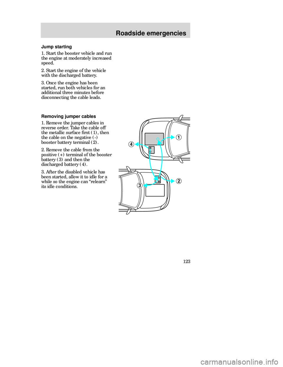
Removing jumper cables
1. Remove the jumper cables in
reverse order. Take the cable off
the metallic surface first (1), then
the cable on the negative (-)
booster battery terminal (2).
2. Remove the cable from the
positive (+) terminal of the booster
battery (3) and then the
discharged battery (4).
3. After the disabled vehicle has
been started, allow it to idle for a
while so the engine can “relearn”
its idle conditions.
2
1
3
4
CDW IVC1-6Roads en MM 5/15/97 7:53 PM Page 123
Page 125 of 196
Maintenance and care
125 SERVICE RECOMMENDATIONS
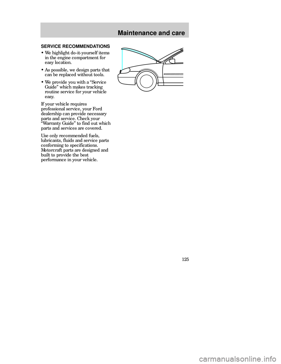
•We highlight do-it-yourself items
in the engine compartment for
easy location.
•As possible, we design parts that
can be replaced without tools.
•We provide you with a “Service
Guide” which makes tracking
routine service for your vehicle
easy.
If your vehicle requires
professional service, your Ford
dealership can provide necessary
parts and service. Check your
“Warranty Guide” to find out which
parts and services are covered.
Use only recommended fuels,
lubricants, fluids and service parts
conforming to specifications.
Motorcraft parts are designed and
built to provide the best
performance in your vehicle.
CDW VA1-19Maint en MM 5/15/97 7:55 PM Page 125
Page 126 of 196
Maintenance and care
126Precautions when servicing
your vehicle
Be especially careful when
inspecting or servicing your
vehicle. Here are some general
precautions for your safety:
•Do not work on a hot engine.
The cooling fan is automatic
and may come on at any
time. Always disconnect the
negative terminal of the battery
before working near the fan.
•If you must work with the engine
running, avoid wearing loose
clothing or jewelry that could get
caught in moving parts. Take
precautions with long hair.
•Do not work on a vehicle with the
engine running in an enclosed
space, unless you are sure you
have enough ventilation.
•Keep all lit cigarettes, open
flames and other lit material
away from the battery and all fuel
related parts.
If you disconnect the battery, the
engine must “relearn” its idle
conditions before your vehicle will
drive properly, as explained under
Battery in this chapter.
CDW VA1-19Maint en MM 5/15/97 7:55 PM Page 126
Page 127 of 196

Maintenance and care
127 Working with engine off
(automatic transaxle)
1. Set the parking brake fully and
ensure the gearshift is securely
latched in P (Park).
2. Turn off the engine and remove
the key.
3. Block the wheels to prevent the
vehicle from moving unexpectedly.
Working with engine off
(manual transaxle)
1. Set the parking brake, depress
the clutch and place the gearshift
in 1 (first) or R (Reverse).
2. Turn off the engine and remove
the key.
3. Block the wheels to prevent the
vehicle from moving unexpectedly.
CDW VA1-19Maint en MM 5/15/97 7:55 PM Page 127
Page 128 of 196

Maintenance and care
128Working with engine on
(automatic transaxle)
1. Set the parking brake fully and
ensure the gearshift is securely
latched in P (Park).
2. Block the wheels to prevent the
vehicle from moving unexpectedly.
Do not start your engine with
the air cleaner removed and
do not remove it while the engine is
running.
Working with engine on
(manual transaxle)
1. Set the parking brake, depress
the clutch and place the gearshift
in neutral.
2. Block the wheels to prevent the
vehicle from moving unexpectedly.
CDW VA1-19Maint en MM 5/15/97 7:55 PM Page 128
Page 129 of 196
Maintenance and care
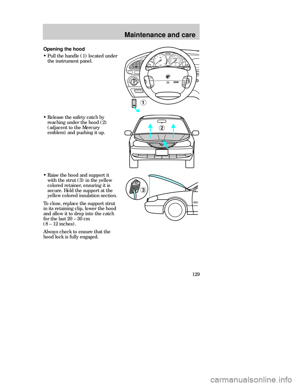
129 Opening the hood
•Pull the handle (1) located under
the instrument panel.
MIRRORS
000123000010 20 3040506070
80
90
100
110
120
130MPH20 406055
80120 100
140
160
180
200EF 1
/
2UNLEADED FUEL ONLY12
03x 1000
4
5
6
7
8
NORMALBRAKE
CHECK
ENGINE TRACTION
CONTROLO/D
OFF
1
Off
ResSet
AccCoast
On
•Release the safety catch by
reaching under the hood (2)
(adjacent to the Mercury
emblem) and pushing it up.
2
3
•Raise the hood and support it
with the strut (3) in the yellow
colored retainer, ensuring it is
secure. Hold the support at the
yellow colored insulation section.
To close, replace the support strut
in its retaining clip, lower the hood
and allow it to drop into the catch
for the last 20 – 30 cm
(8 – 12 inches).
Always check to ensure that the
hood lock is fully engaged.
CDW VA1-19Maint en MM 5/15/97 7:55 PM Page 129
Page 130 of 196
Maintenance and care
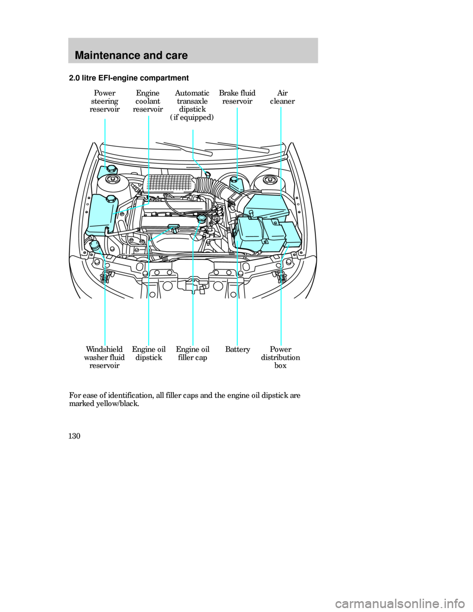
130For ease of identification, all filler caps and the engine oil dipstick are
marked yellow/black. 2.0 litre EFI-engine compartment
Power
steering
reservoirEngine
coolant
reservoirAutomatic
transaxle
dipstick
(if equipped)Brake fluid
reservoir
BatteryWindshield
washer fluid
reservoirEngine oil
dipstickPower
distribution
box
Air
cleaner
Engine oil
filler cap
CDW VA1-19Maint en MM 5/15/97 7:55 PM Page 130