fuse box Mercury Mystique 1998 Owner's Manuals
[x] Cancel search | Manufacturer: MERCURY, Model Year: 1998, Model line: Mystique, Model: Mercury Mystique 1998Pages: 196, PDF Size: 1.65 MB
Page 109 of 196

Roadside emergencies
109 Even after a fuse is replaced, it will
continue to blow if the cause of the
overload is not identified and
corrected. If the fuse continues to
blow, have the vehicle’s electrical
system checked by your dealer or a
qualified service technician.
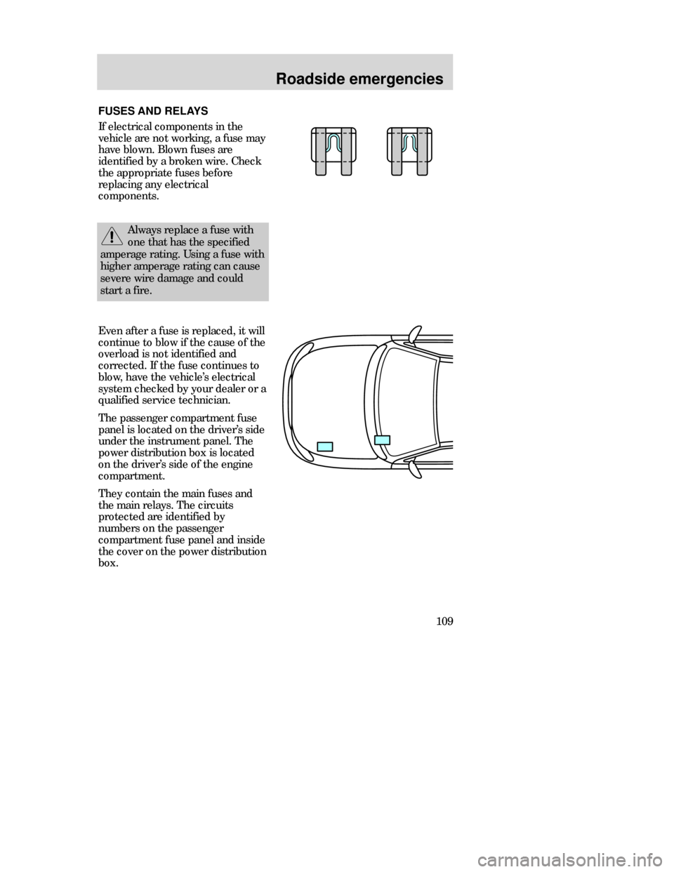
The passenger compartment fuse
panel is located on the driver’s side
under the instrument panel. The
power distribution box is located
on the driver’s side of the engine
compartment.
They contain the main fuses and
the main relays. The circuits
protected are identified by
numbers on the passenger
compartment fuse panel and inside
the cover on the power distribution
box.
FUSES AND RELAYS
If electrical components in the
vehicle are not working, a fuse may
have blown. Blown fuses are
identified by a broken wire. Check
the appropriate fuses before
replacing any electrical
components.
Always replace a fuse with
one that has the specified
amperage rating. Using a fuse with
higher amperage rating can cause
severe wire damage and could
start a fire.
CDW IVC1-6Roads en MM 5/15/97 7:53 PM Page 109
Page 110 of 196

Roadside emergencies
110
1
2
Power distribution box
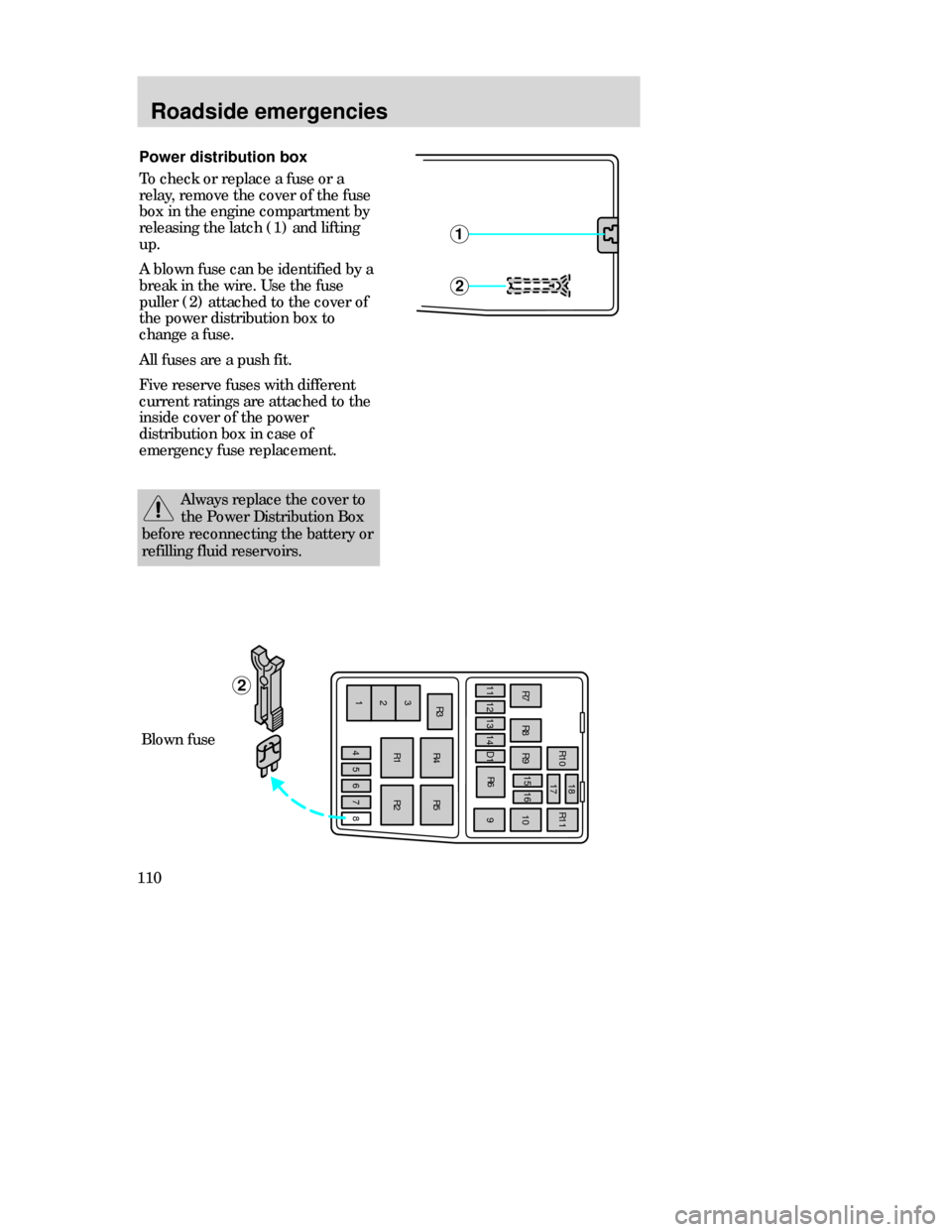
To check or replace a fuse or a
relay, remove the cover of the fuse
box in the engine compartment by
releasing the latch (1) and lifting
up.
A blown fuse can be identified by a
break in the wire. Use the fuse
puller (2) attached to the cover of
the power distribution box to
change a fuse.
All fuses are a push fit.
Five reserve fuses with different
current ratings are attached to the
inside cover of the power
distribution box in case of
emergency fuse replacement.
2
R10
R91516R11
10 18
17
R8 R7
11121314R6
R4 R3
3
2
1R1R2 R5 D1
456789
Blown fuse
Always replace the cover to
the Power Distribution Box
before reconnecting the battery or
refilling fluid reservoirs.
CDW IVC1-6Roads en MM 5/15/97 7:53 PM Page 110
Page 111 of 196

Roadside emergencies
111 Ampere
rating
Power distribution box (engine compartment)
Color
Circuits protected
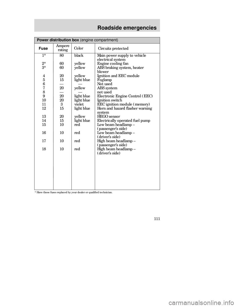
1*
2*
3*
4
5
6
7
8
9
10
11
12
13
14
15
16
17
1880
60
60
20
15
—
20
—
20
20
3
15
20
15
10
10
10
10black
yellow
yellow
yellow
light blue
—
yellow
—
light blue
light blue
violet
light blue
yellow
light blue
red
red
red
redMain power supply to vehicle
electrical system
Engine cooling fan
ABS braking system, heater
blower
Ignition and EEC module
Foglamp
Not used
ABS system
not used
Electronic Engine Control (EEC)
Ignition switch
EEC ignition module (memory)
Horn and hazard flasher warning
system
HEGO sensor
Electrically operated fuel pump
Low beam headlamp –
(passenger’s side)
Low beam headlamp –
(driver’s side)
High beam headlamp –
(passenger’s side)
High beam headlamp –
(driver’s side)
* Have these fuses replaced by your dealer or qualified technician.
Fuse
CDW IVC1-6Roads en MM 5/15/97 7:53 PM Page 111
Page 112 of 196

Roadside emergencies
112Passenger compartment fuse
panel
To check or change a fuse or a
relay, open the fuse box by pulling
down the lock release lever (1).
1
Power distribution box (engine compartment)
Relay
Circuits switched
R 1
R 2
R 3
R 4
R 5
R 6
R 7
R 8
R 9
R 10
R 11
D1
Daytime running lights
Radiator fan relay (high speed)
Air conditioning
Air conditioning clutch relay
Radiator fan relay (low speed)
Starter solenoid
Horn
Electrically operated fuel pump
Low beam headlamps
High beam headlamps
EEC module
Reverse voltage protection
CDW IVC1-6Roads en MM 5/15/97 7:53 PM Page 112
Page 113 of 196

Roadside emergencies
113 A blown fuse can be identified by a
break in the wire. Use the fuse
puller (2) attached to the cover of
the power distribution box to
change a fuse.
All fuses are a push fit.
Five reserve fuses with different
current ratings are attached to the
inside cover of the power
distribution box in case of
emergency fuse replacement.
192021R16 R15
R14 R12R13
22232425262728
29303132333435363738
D2
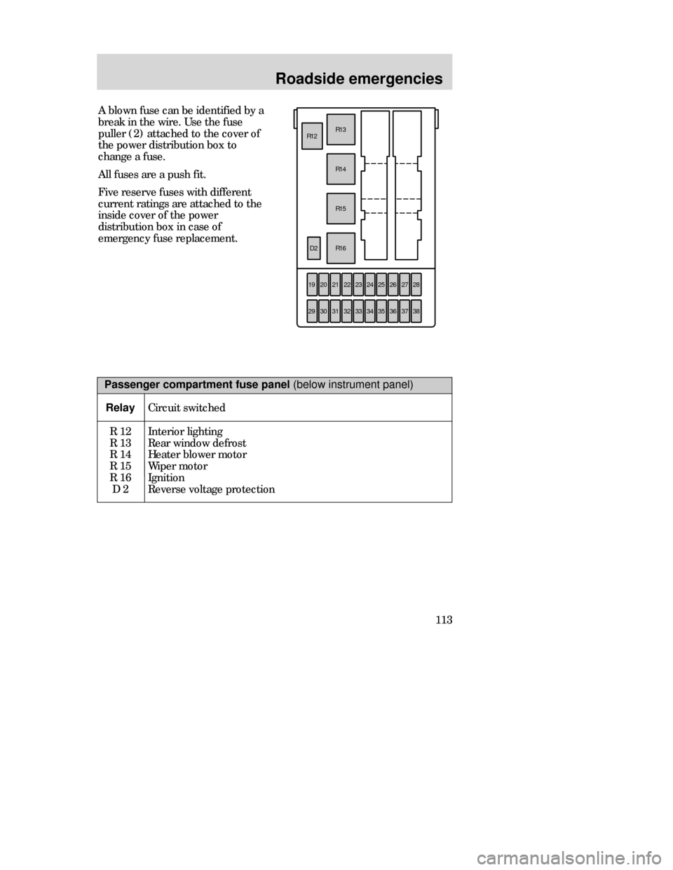
Passenger compartment fuse panel (below instrument panel)
Relay
Circuit switched
R 12
R 13
R 14
R 15
R 16
D 2Interior lighting
Rear window defrost
Heater blower motor
Wiper motor
Ignition
Reverse voltage protection
CDW IVC1-6Roads en MM 5/15/97 7:53 PM Page 113
Page 115 of 196

Roadside emergencies
115
Fuse rating
7.5 amp
10 amp
15 amp
20 amp
30 amp
30 amp fuse link
40 amp
60 amp fuse link
80 amp fuse link
100 amp fuse linkColor
brown
red
blue
yellow
light green
pink
green
yellow
black
blue
Relay
R 18
R 20
R 21
R 22
R 23
R 24
R 25
R 26
“One touch” switch
(driver’s window)
Not used
Not used
Foglamps
Turn signals
Panic alarm –
driver’s side
Panic alarm –
right-hand side
Not usedDriver’s door
—
—
Module bracket
Steering column
Door lock module bracket
Door lock module bracket
—
Circuits switchedLocation Standard fuse amperage ratings
and colors
3 ampviolet
Auxiliary relays (outside of fuse boxes)
CDW IVC1-6Roads en MM 5/15/97 7:53 PM Page 115
Page 194 of 196

Index
194MPage
Maintenance (see Servicing)
Manual transaxle
backing up (reverse) . . . . . . . . .95
clutch . . . . . . . . . . . . . . . . . . . . .93
fluid, capacity . . . . . . . . . . . . .184
fluid, checking and adding . . .141
shift speeds . . . . . . . . . . . . . . . .94
Mileage, calculating fuel
economy . . . . . . . . . . . . . . . . . . .162
Mirrors
side view mirrors (power) . . . .17
Motorcraft parts . . . . . . . . . . . .183
N
National Highway Traffic Safety
Administration . . . . . . . . . . . . . .189
O
Octane rating . . . . . . . . . . . . . . .160
Odometer . . . . . . . . . . . . . . . . . . .13
Oil (see Engine oil)
Oil filter . . . . . . . . . . . . . . .133, 183
On-board diagnostic (OBDII)
system . . . . . . . . . . . . . . . . . . . .166
Overdrive . . . . . . . . . . . . . . . . .7, 90
Overhead controls . . . . . . . . . . . .33
P
Panel dimmer control . . . . . . . . .16
Panic alarm, remote entry sytem39
Parking brake . . . . . . . . . . . . . . .86
Parts (see Motorcraft parts) . . .138
Passenger compartment
air filter (see Cabin air filter) . .147
Passive Anti-Theft
System (PATS) . . . . . . . . . . . . . .41PPage
Power distribution box
(see Fuses)
Power door locks . . . . . . . . . . . . .34
Power features
mirrors . . . . . . . . . . . . . . . . . . . .17
seats . . . . . . . . . . . . . . . . . . . . . .45
sunroof . . . . . . . . . . . . . . . . . . . .33
windows . . . . . . . . . . . . . . . . . . .34
Power steering
fluid, checking and adding . . .140
fluid, refill capacity . . . . . . . . .184
fluid, specification . . . . . . . . . .185
R
Radio (see Audio system) . . . . . .18
Rear window defroster . . . . . . . .16
Refill capacities for fluids . . . . .184
Relays . . . . . . . . . . . . . . . . . . . . .109
Remote control
luggage compartment . . . . . . . .36
Remote entry system
locking/unlocking doors . . . . . .38
opening the trunk . . . . . . . . . . .39
panic alarm . . . . . . . . . . . . . . . .39
replacing the batteries . . . . . . .39
replacement/additional
transmitters . . . . . . . . . . . . . . . .40
Repairing paint chips . . . . . . . .178
Reporting safety defects . . . . . .189
Restraints, safety . . . . . . . . . . . . .47
Rotating the tires . . . . . . . . . . . .152
CDW_Index_en _MM 5/15/97 8:00 PM Page 194