steering Mercury Mystique 1998 Owner's Manuals
[x] Cancel search | Manufacturer: MERCURY, Model Year: 1998, Model line: Mystique, Model: Mercury Mystique 1998Pages: 196, PDF Size: 1.65 MB
Page 4 of 196

4
Instrumentation
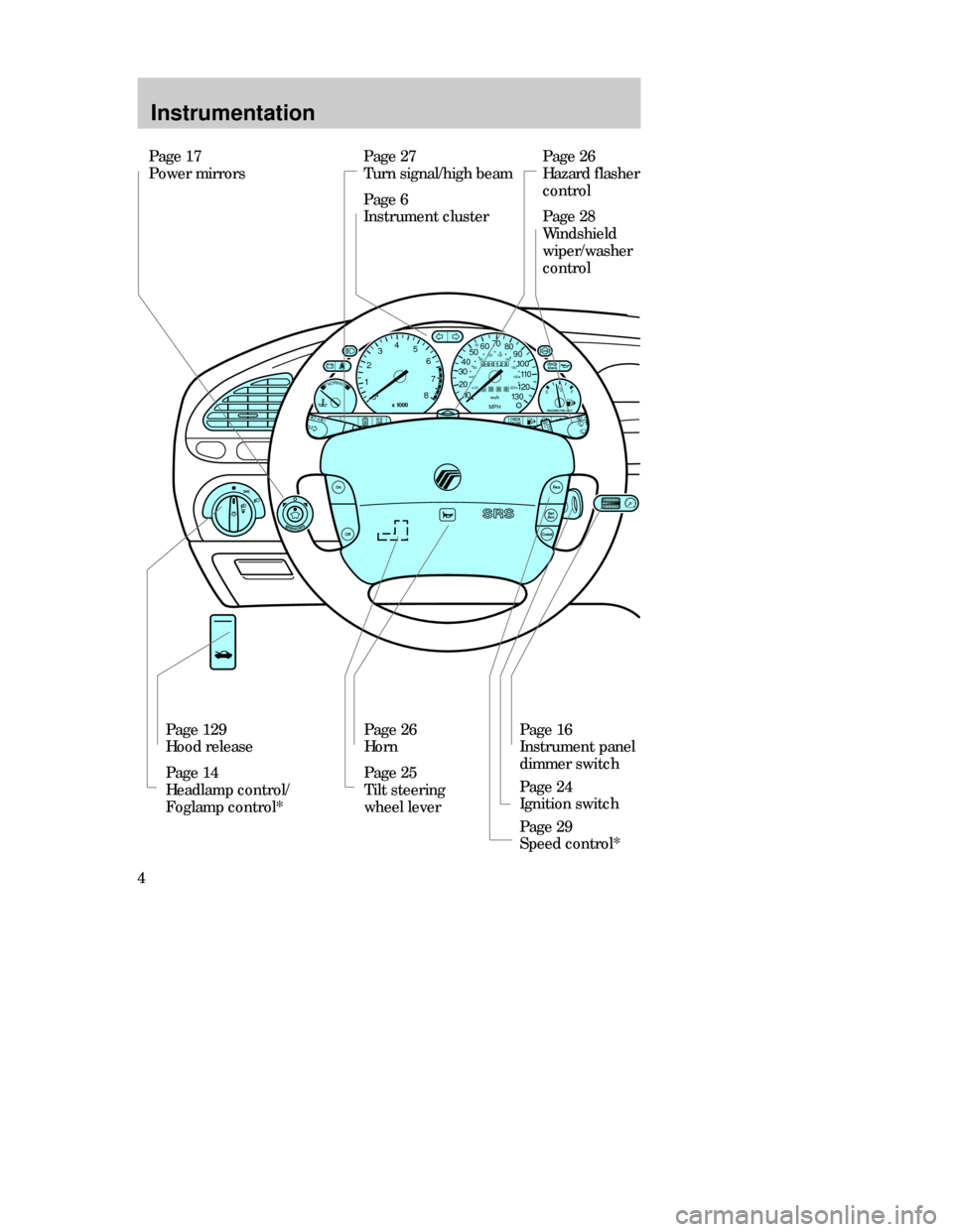
Page 27
Turn signal/high beam
Page 6
Instrument clusterPage 26
Hazard flasher
control
Page 28
Windshield
wiper/washer
control
Page 129
Hood release
Page 14
Headlamp control/
Foglamp control*Page 26
Horn
Page 25
Tilt steering
wheel leverPage 16
Instrument panel
dimmer switch
Page 24
Ignition switch
Page 29
Speed control* Page 17
Power mirrors
CHECK
ENGINEO/D
OFF
Off
Res
Set
Acc
Coast
On
MIRRORS
NORMAL12
03
x 1000
4
5
6
7
8
000123
000010 20 3040506070
80
90
100
110
120
130MPH
20 4060
55
80120 100
140
160
180
200
EF 1
/
2
UNLEADED FUEL ONLY
BRAKE
CDW IIA2Instrum_en MM 5/15/97 7:43 PM Page 4
Page 24 of 196

Controls and features
24STEERING COLUMN
CONTROLS
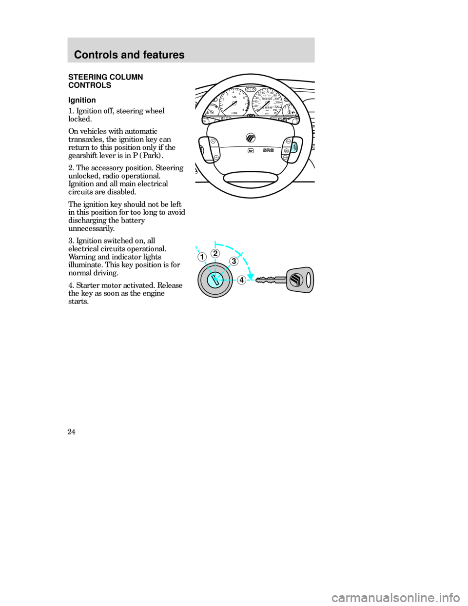
Ignition
1. Ignition off, steering wheel
locked.
On vehicles with automatic
transaxles, the ignition key can
return to this position only if the
gearshift lever is in P (Park).
2. The accessory position. Steering
unlocked, radio operational.
Ignition and all main electrical
circuits are disabled.
The ignition key should not be left
in this position for too long to avoid
discharging the battery
unnecessarily.
3. Ignition switched on, all
electrical circuits operational.
Warning and indicator lights
illuminate. This key position is for
normal driving.
4. Starter motor activated. Release
the key as soon as the engine
starts.
3
4
21
MIRRORS
000123
000010 20 3040506070
80
90
100
110
120
130MPH20 406055
80120 100
140
160
180
200EF 1
/
2UNLEADED FUEL ONLY
12
03x 1000
4
5
6
7
8
NORMALBRAKE
CHECK
ENGINE TRACTION
CONTROLO/D
OFF
Off
Res
Set
AccCoast
On
CDW IIIC3Cont en MM 5/15/97 7:45 PM Page 24
Page 25 of 196

Controls and features
25
POWERAUDIOAM/FM
SCAN
SEEK 312645ANSSIDE1-2EJECTVOLUME
MIRRORSDEF
LO
HIOFFPNL/FLR
PANEL
A/CFLOOR
FLR
DEF
MAX
A/C
000123
000010 20 3040506070
80
90
100
110
120
130MPH20 406055
80120 100
140
160
180
200EF 1
/
2UNLEADED FUEL ONLY
12
03x 1000
4
5
6
7
8
NORMALBRAKE
CHECK
ENGINE TRACTION
CONTROLO/D
OFF
:
I0 20
Off
Res
Set
AccCoast
On
Tilt steering
Pull the locking lever on the
steering column cover up to adjust
the steering column position.
Secure the wheel by pushing the
locking lever down.
Never adjust the steering
wheel while the vehicle is
moving.
CDW IIIC3Cont en MM 5/15/97 7:45 PM Page 25
Page 28 of 196

Controls and features
28
Wipers
Lift the windshield wiper lever to
the desired speed interval.
•Intermittent: push lever up to the
first position.
•Low: push lever up to the second
position.
•High: push lever up to the third
position.
For a single wipe, push the lever
downward.
Windshield wipers and washer
Intermittent wiper control
(if equipped)
Rotate the variable intermittent
wiper control to the desired speed.
1 = Short time interval
6 = Extended time interval
Washer
Pull the lever toward the steering
wheel. The washer operates in
conjunction with the windshield
wipers.
CDW IIIC3Cont en MM 5/15/97 7:45 PM Page 28
Page 85 of 196

Driving
85
Two important
rules when
braking in
emergencies with
ABS:
1.
Apply full force
on both brake
and clutch pedal
(if equipped).
Braking with ABS
•In an emergency, apply full force
on the brake pedal. In vehicles
with manual transaxles, you must
also depress the clutch pedal.
The anti-lock braking system will
be activated immediately,
allowing you to retain full
steering control of your vehicle
and, providing there is sufficient
space, will enable you to avoid
obstacles.
•We recommend that you
familiarize yourself with this
braking technique. However,
avoid taking any unnecessary
risks.
2.
Steer around the
obstacle. No matter
how hard you brake,
steering control is
maintained.
CDW IVB1-10Driving en MM 5/15/97 7:51 PM Page 85
Page 89 of 196

Driving
89 The console-mounted gearshift will
lock when you turn the key to the
lock position. When the gearshift is
in any position except P (Park),
the ignition key cannot be turned
to lock or removed from the
steering column. To remove the
key, the gearshift lever must be in
P (Park).
Once the gearshift is secure in the
desired position, release the brake
pedal and use the accelerator as
necessary.
Driving
Never leave a vehicle
unattended while it is
running.
•P(Park)
Always come to a complete stop
before shifting into P (Park). This
locks the transaxle and prevents
the front wheels from rotating.
•R(Reverse)
The vehicle only moves backward.
Always come to a complete stop
before shifting in or out of R
(Reverse).P=Park. . . . . . . . . . . . . .
R=Reverse. . . . . . . . . . .
N=Neutral. . . . . . . . . . . .
D=Drive: Gear 1 to 4
with overdrive. . . . . .
Gear 1 to 3
with overdrive
cancelled. . . . . . . . . .
2=Gear 2. . . . . . . . . . . .
1=Gear 1. . . . . . . . . . . .
CDW IVB1-10Driving en MM 5/15/97 7:51 PM Page 89
Page 102 of 196

Driving
102Preparing to tow
Use the proper equipment for
towing a trailer and make sure that
it is properly attached to your
vehicle. See your dealer or a
reliable trailer retailer if you
require assistance.
Auxiliary coolers are recommended
for the power steering system and
automatic transaxle system if you
are planning on:
•Traveling farther than 80 km
(50miles).
•Towing in hilly terrain.
•Towing frequently.
Towing trailers beyond the
maximum recommended
gross trailer weight exceeds the
limit of the vehicle and could
result in engine damage, transaxle
damage, structural damage, loss of
control, and personal injury.
Do not exceed the maximum loads
listed on the Safety Compliance
Certification Label. For load
specification terms found on the
label, refer to Loading your
vehiclein this chapter. Remember
to figure in the tongue load of your
loaded vehicle when figuring the
total weight.
CDW IVB1-10Driving en MM 5/15/97 7:51 PM Page 102
Page 115 of 196

Roadside emergencies
115
Fuse rating
7.5 amp
10 amp
15 amp
20 amp
30 amp
30 amp fuse link
40 amp
60 amp fuse link
80 amp fuse link
100 amp fuse linkColor
brown
red
blue
yellow
light green
pink
green
yellow
black
blue
Relay
R 18
R 20
R 21
R 22
R 23
R 24
R 25
R 26
“One touch” switch
(driver’s window)
Not used
Not used
Foglamps
Turn signals
Panic alarm –
driver’s side
Panic alarm –
right-hand side
Not usedDriver’s door
—
—
Module bracket
Steering column
Door lock module bracket
Door lock module bracket
—
Circuits switchedLocation Standard fuse amperage ratings
and colors
3 ampviolet
Auxiliary relays (outside of fuse boxes)
CDW IVC1-6Roads en MM 5/15/97 7:53 PM Page 115
Page 124 of 196

Roadside emergencies
124If towing is necessary, it is
recommended that your vehicle be
towed with a wheel lift or flatbed
equipment. Do not tow with
slingbelt equipment. Ford Motor
Company has not developed or
approved a T-hook or slingbelt
towing procedure.
TOWING YOUR VEHICLE
BEHIND ANOTHER VEHICLE
Before you have your vehicle
towed:
•release the parking brake,
•move the gearshift to N
(Neutral),
•turn the ignition to the off
position and
•unlock the steering wheel.
Do not tow your vehicle at a speed
faster than 55 km/h (35 mph) or
for a distance greater than 80 km
(55 miles) unless the drive wheels
are placed on dollies. WRECKER TOWING
CDW VA1-19Maint en MM 5/15/97 7:55 PM Page 124
Page 130 of 196

Maintenance and care
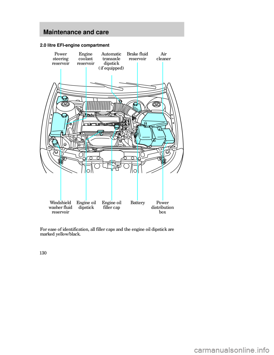
130For ease of identification, all filler caps and the engine oil dipstick are
marked yellow/black. 2.0 litre EFI-engine compartment
Power
steering
reservoirEngine
coolant
reservoirAutomatic
transaxle
dipstick
(if equipped)Brake fluid
reservoir
BatteryWindshield
washer fluid
reservoirEngine oil
dipstickPower
distribution
box
Air
cleaner
Engine oil
filler cap
CDW VA1-19Maint en MM 5/15/97 7:55 PM Page 130