tow Mercury Mystique 2000 Owner's Manuals
[x] Cancel search | Manufacturer: MERCURY, Model Year: 2000, Model line: Mystique, Model: Mercury Mystique 2000Pages: 248, PDF Size: 2.2 MB
Page 2 of 248

Introduction
2ICONS
Indicates a warning. Read the
following section on Warnings for
a full explanation.
Indicates that vehicle information
related to recycling and other
environmental concerns will follow.
We must all play our part in
protecting the environment.
Correct vehicle usage and the
authorized disposal of waste
cleaning and lubrication materials
are significant steps toward this
aim.
BREAKING IN YOUR VEHICLE
There are no particular breaking-in
rules for your vehicle. Simply avoid
driving too fast during the first
1 600 km (1 000 miles). Vary
speeds frequently. This is
necessary to give the moving parts
a chance to break in.
WARNINGS
How can you reduce the risk of
personal injury and prevent
possible damage to others, your
vehicle, and its equipment?
In this owner’s guide, answers to
such questions are contained in
comments highlighted by the
warning triangle symbol.
11MIten 24.6.99 15:01 Uhr Seite 2
Page 13 of 248

Instrumentation
13 What you should do if the check
engine light illuminates
Light turns on solid:
This means that the OBD II system
has detected a malfunction.
Temporary malfunctions may cause
your check engine light to
illuminate. Examples are:
• The vehicle has run out of fuel
(The engine may misfire or run
poorly.)
• Poor fuel quality or water in the
fuel
• The fuel cap may not have been
securely tightened. The check engine indicator light
illuminates when the ignition is
first turned to the ON position to
check the bulb. If it comes on
after the engine is started, one of
the engine’s emission control
systems may be malfunctioning.
The light may illuminate without a
driveability concern being noted.
The vehicle will usually be drivable
and will not require towing.
12MInen 24.6.99 15:03 Uhr Seite 13
Page 53 of 248

Controls and features
53 •Terrain.Hills, mountains and tall
buildings between your vehicle’s
antenna and the radio station
signal can cause FM reception
problems. Static can be caused on
AM stations by power lines, electric
fences, traffic lights and
thunderstorms. Moving away from
an interfering structure (out of its
“shadow”) returns your reception
to normal.
• Station overload.Weak signals
are sometimes captured by
stronger signals when you pass a
broadcast tower. A stronger signal
may temporarily overtake a weaker
signal and play while the weak
station frequency is displayed.
The audio system automatically
switches to single channel
reception if it will improve the
reception of a station normally
received in stereo.
AUDIO SYSTEM WARRANTIES
AND SERVICE
Refer to the “Warranty Guide” for
audio system warranty information.
If service is necessary, see your
dealer or a qualified technician.
13MCfen 24.6.99 15:06 Uhr Seite 53
Page 57 of 248

Controls and features
57
OFF LO PNL/FLR
PANEL
A/CFLOOR
DEF FLR
DEF
MAX
A/C HI/
POWER AUDIO AM/FM
SCAN
SEEK 31245ANSSIDE 1-2EJECTVOLUME
000123
000010 20 3040506070
80
90
10 0
110
120
13 0MPH20 406055
80120 10 0
14 0
160
18 0
200EF12
03
x 1000
4
5
6
7
8
CHECK
ENGINE TRACTION
CONTROLO/D
OFF
MIRRORS
CLOCK
TRACTION
TROL
CH
Multi-function switch
The turn signal functions are
available only with the ignition
switch on.
Right turn signal
Move the lever up.
Left turn signal
Move the lever down.
Flash-to-pass
Pull the lever toward you and
release quickly for “flash-to-pass”
operation.
High beam heaadlamps
Push the lever toward the
instrument panel.
13MCfen 24.6.99 15:06 Uhr Seite 57
Page 58 of 248

Controls and features
58Wipers
Lift the windshield wiper lever to
the desired speed interval.
• Intermittent: push lever up to the
first position.
• Low: push lever up to the second
position.
• High: push lever up to the third
position.
For a single wipe, push the lever
downward.
Windshield wipers and washer
Intermittent wiper control
(if equipped)
Rotate the variable intermittent
wiper control to the desired speed.
1 = Short time interval
6 = Extended time interval
Washer
Pull the lever toward the steering
wheel. The washer operates in
conjunction with the windshield
wipers.
13MCfen 24.6.99 15:06 Uhr Seite 58
Page 101 of 248

Seating and safety restraints
101
If both tongues do not latch
in the buckle, do not use the
child seat. See your dealer for
repairs.
7. Fasten both halves of the chest
clip below the child’s shoulders and
adjust it to comfortably hold the
shoulder belts in place on the
child’s chest. The color green must
appear in the indicator window
when fastened.
8. Pull the lap portion of the belts
toward you to make sure the crotch
safety belt buckle is properly
fastened and the retractor is
locked.
9. If the belts become too tight,
unbuckle the crotch safety belt
buckle to unlock the retractors,
then reinsert both belt tongues. 6. Insert either the left or the right
safety belt tongue into the single
opening of the crotch safety belt
buckle (it doesn’t matter which
tongue is inserted first). Insert the
other tongue. The color green must
appear in the indicator window on
each tongue when buckled. Allow
belts to retract and fit snugly.
14MSSen 24.6.99 15:16 Uhr Seite 101
Page 102 of 248

Seating and safety restraints
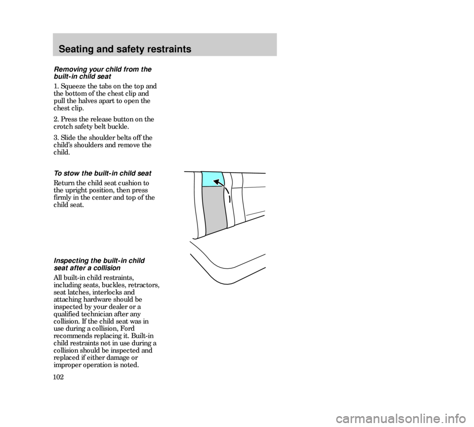
102To stow the built-in child seat
Return the child seat cushion to
the upright position, then press
firmly in the center and top of the
child seat.
Inspecting the built-in child
seat after a collision
All built-in child restraints,
including seats, buckles, retractors,
seat latches, interlocks and
attaching hardware should be
inspected by your dealer or a
qualified technician after any
collision. If the child seat was in
use during a collision, Ford
recommends replacing it. Built-in
child restraints not in use during a
collision should be inspected and
replaced if either damage or
improper operation is noted. Removing your child from the
built-in child seat
1. Squeeze the tabs on the top and
the bottom of the chest clip and
pull the halves apart to open the
chest clip.
2. Press the release button on the
crotch safety belt buckle.
3. Slide the shoulder belts off the
child’s shoulders and remove the
child.
14MSSen 24.6.99 15:16 Uhr Seite 102
Page 106 of 248

Seating and safety restraints
1068. Allow the safety belt to retract to
remove any slack in the belt.
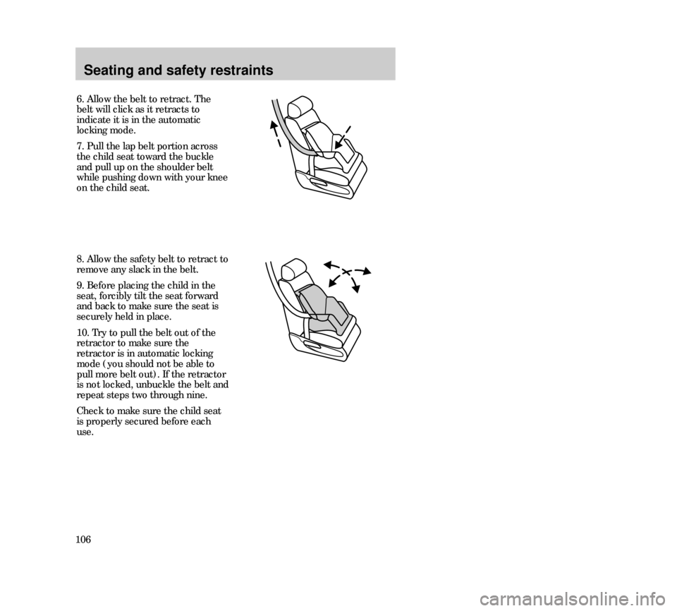
9. Before placing the child in the
seat, forcibly tilt the seat forward
and back to make sure the seat is
securely held in place.
10. Try to pull the belt out of the
retractor to make sure the
retractor is in automatic locking
mode (you should not be able to
pull more belt out). If the retractor
is not locked, unbuckle the belt and
repeat steps two through nine.
Check to make sure the child seat
is properly secured before each
use.
6. Allow the belt to retract. The
belt will click as it retracts to
indicate it is in the automatic
locking mode.
7. Pull the lap belt portion across
the child seat toward the buckle
and pull up on the shoulder belt
while pushing down with your knee
on the child seat.
14MSSen 24.6.99 15:16 Uhr Seite 106
Page 119 of 248

Driving
119 TRACTION CONTROL
(if equipped)
This system prevents wheel spin at
all speeds. The control will toggle
this function on and off, but the
feature defaults to on after each
cycle of the ignition key.
The traction control system
controls excessive wheel spin by
automatically applying and
releasing the brakes in conjunction
with engine torque reductions.
This can occur when accelerating
on a slippery road, a loose surface
or when pulling away on a hill. The
traction control lamp flashes on the
instrument panel when the system
is functioning to regulate tire
traction.
When the ignition is turned to the
on position, the traction control
system light comes on for
approximately three (3) seconds. If
the light does not come on when
the ignition is turned to the on
position or if it remains on when
the traction control system is
turned on, have the system
serviced by your dealer or a
qualified service technician. You
can continue to drive and do not
need to have the vehicle towed in.
You should not take unnecessary
driving risks because of the
system’s safety potential.
22MDren 24.6.99 15:26 Uhr Seite 119
Page 131 of 248

Driving
131 GCW (Gross Combined Weight)
The GCW is the maximum
combined weight of the towing
vehicle (including passengers and
cargo) and the loaded trailer. The
GCW is specified by the
manufacturer to indicate the
combined maximum loaded weight
that the vehicle is designed to tow. GAWR (Gross Axle Weight
Rating)
Carrying capacity for each axle
system (front and rear). The
GAWR is specific to each vehicle
and is listed on the Safety
Compliance Certification Label on
the driver’s door pillar. GVWR (Gross Vehicle Weight
Rating)
Maximum total weight of the base
vehicle, passengers, optional
equipment and cargo. The GVWR is
specific to each vehicle and is listed
on the Safety Compliance
Certification Label on the driver’s
door pilar.
22MDren 24.6.99 15:26 Uhr Seite 131