ABS Mercury Sable 1999 Owner's Manuals
[x] Cancel search | Manufacturer: MERCURY, Model Year: 1999, Model line: Sable, Model: Mercury Sable 1999Pages: 216, PDF Size: 1.33 MB
Page 4 of 216
CRUISE
RPMx10000 1234
5
6
7EFC HFUEL DOOR>
SERVICE
ENGINE
SOON1020304050 60
70
80
90
100
110
00 20406080100
120
140
160
180P R N D D 1MPH km/h0012200013P!
BRAKEABS
+ –
UNLEADED FUEL ONLY
THEFT LOW
COOLANTO/D
OFF
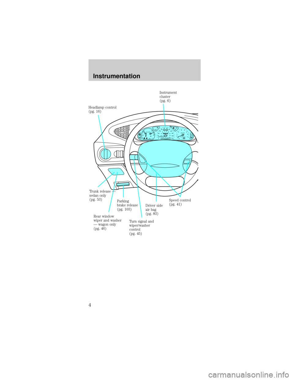
Parking
brake release
(pg. 103) Headlamp control
(pg. 16)
Speed control
(pg. 41)
Driver side
air bag
(pg. 83) Trunk release Ð
sedan only
(pg. 53)
Rear window
wiper and washer
Ð wagon only
(pg. 46)Turn signal and
wiper/washer
control
(pg. 45)Instrument
cluster
(pg. 6)
Instrumentation
4
Page 6 of 216
WARNING LIGHTS AND CHIMES
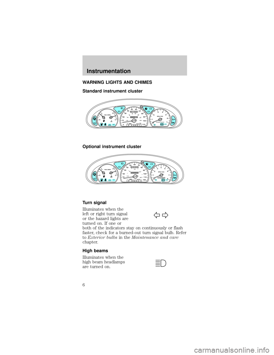
Standard instrument cluster
Optional instrument cluster
Turn signal
Illuminates when the
left or right turn signal
or the hazard lights are
turned on. If one or
both of the indicators stay on continuously or flash
faster, check for a burned-out turn signal bulb. Refer
toExterior bulbsin theMaintenance and care
chapter.
High beams
Illuminates when the
high beam headlamps
are turned on.
CRUISE
RPMx1000
0 1234
5
6
7EFC H
FUEL DOOR>
SERVICE
ENGINE
SOON1020304050 60
70
80
90
100
110
00 20406080100
120
140
160
180P R N D D 1MPH km/h
00
122
00013
P!
BRAKEABS
+ –
UNLEADED FUEL ONLY
THEFT LOW
COOLANTO/D
OFF
EFC H
FUEL DOOR>
SERVICE
ENGINE
SOON
THEFT102030405060
70
80
90
100
1202060100
140
180
P R N D 2 1MPH km/h
00
000
00000
P!
BRAKELOW
COOLANT
+ –
110CRUISE
RPMx1000
ABSO/D
OFFPREMIUM UNLEADED
FUEL RECOMMENDED0 1234
5
6
78
Instrumentation
6
Page 9 of 216
of a tank indicated on the fuel gauge (refer toFuel
gaugein this chapter for more information). The
ignition must be in the ON position for this lamp to
illuminate. The lamp will also illuminate for several
seconds after the ignition is turned to the ON
position regardless of the fuel level.
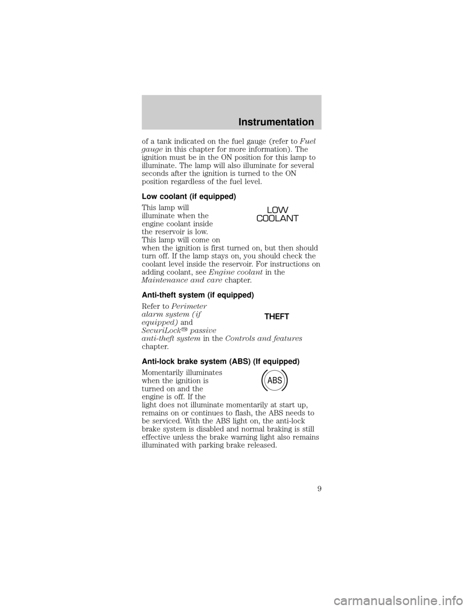
Low coolant (if equipped)
This lamp will
illuminate when the
engine coolant inside
the reservoir is low.
This lamp will come on
when the ignition is first turned on, but then should
turn off. If the lamp stays on, you should check the
coolant level inside the reservoir. For instructions on
adding coolant, seeEngine coolantin the
Maintenance and carechapter.
Anti-theft system (if equipped)
Refer toPerimeter
alarm system (if
equipped)and
SecuriLockypassive
anti-theft systemin theControls and features
chapter.
Anti-lock brake system (ABS) (If equipped)
Momentarily illuminates
when the ignition is
turned on and the
engine is off. If the
light does not illuminate momentarily at start up,
remains on or continues to flash, the ABS needs to
be serviced. With the ABS light on, the anti-lock
brake system is disabled and normal braking is still
effective unless the brake warning light also remains
illuminated with parking brake released.
LOW
COOLANT
THEFT
ABS
Instrumentation
9
Page 12 of 216

GAUGES
Standard instrument cluster gauges
Optional instrument cluster gauges
Speedometer
Indicates the current vehicle speed.
²Standard instrument
cluster
CRUISE
RPMx1000
0 1234
5
6
7EFC H
FUEL DOOR>
SERVICE
ENGINE
SOON1020304050 60
70
80
90
100
110
00 20406080100
120
140
160
180P R N D D 1MPH km/h
00
122
00013
P!
BRAKEABS
+ –
UNLEADED FUEL ONLY
THEFT LOW
COOLANTO/D
OFF
EFC H
FUEL DOOR>
SERVICE
ENGINE
SOON
THEFT102030405060
70
80
90
100
1202060100
140
180
P R N D 2 1MPH km/h
00
000
00000
P!
BRAKELOW
COOLANT
+ –
110CRUISE
RPMx1000
ABSO/D
OFFPREMIUM UNLEADED
FUEL RECOMMENDED0 1234
5
6
78
1020304050 60
70
80
90
100
110
0
0 20406080100
120
140
160
180P R N D D 1MPH km/h
00
000
00000
Instrumentation
12
Page 83 of 216
Safety belt maintenance
Inspect the safety belt systems periodically to make
sure they work properly and are not damaged.
Inspect the safety belts to make sure there are no
nicks, wears or cuts, replacing if necessary. All
safety belt assemblies, including retractors, buckles,
front seat belt buckle assemblies (slide bar)(if
equipped), shoulder belt height adjusters (if
equipped), child safety seat tether bracket
assemblies (if equipped), and attaching hardware,
should be inspected after a collision. Ford
recommends that all safety belt assemblies used in
vehicles involved in a collision be replaced. However,
if the collision was minor and a qualified technician
finds that the belts do not show damage and
continue to operate properly, they do not need to be
replaced. Safety belt assemblies not in use during a
collision should also be inspected and replaced if
either damage or improper operation is noted.
Failure to inspect and if necessary replace
the safety belt assembly under the above
conditions could result in severe personal injuries
in the event of a collision.
Refer toCleaning and maintaining the safety
beltsin theMaintenance and caresection.
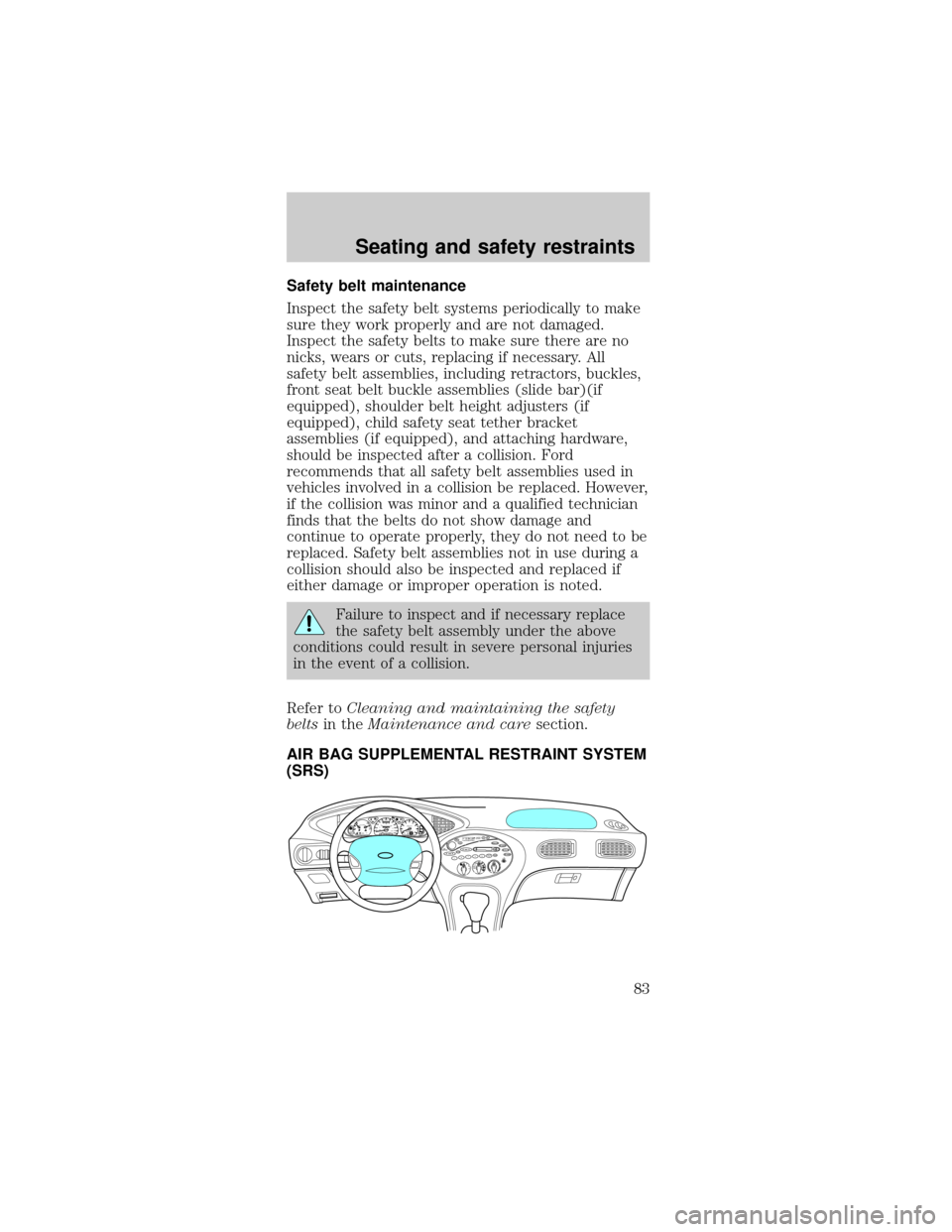
AIR BAG SUPPLEMENTAL RESTRAINT SYSTEM
(SRS)
BASSTREBBALFADEREWFFEJECT1234
56wTAPE SIDETAPE
R-DEFTUNESEEKSCAN AM
FMMH
LO
HIOFF
A/C
MAX
A/CVENTVOL
PUSH-ONwSTFM 12
AMCBLRFEFC HFUEL DOOR>SERVICE
ENGINE
SOONLOW
COOLANTTHEFT102030405060
70
80
90
100
1202060100
140
180P R N D 2 1MPH km/h0000000000P!
BRAKE+ –110CRUISERPMx1000ABSO/D
OFFREAR
LAMP
OUTPREMIUM UNLEADED
FUEL RECOMMENDED0 1234
5
6
78
Seating and safety restraints
83
Page 98 of 216

Make sure the corresponding lights illuminate briefly.
If a light fails to illuminate, have the vehicle
serviced.
²If the driver's safety belt is fastened, the
light
may not illuminate.
STARTING THE ENGINE
1. Turn the key to 5
(START) without
pressing the
accelerator pedal and
release as soon as the
engine starts. The key
will return to 4 (ON).
2. If the temperature is above ±12É C (10É F) and
the engine does not start within five seconds on the
first try, turn the key to OFF, wait ten seconds and
try again.
3. If the temperature is below -12ÉC (10ÉF) and the
engine does not start in fifteen seconds on the first
try, turn the key OFF and wait ten seconds and try
again. If the engine does not start in two attempts,
depress the accelerator and start the engine while
holding the accelerator down to the floor. Release
the accelerator when the engine starts.
4. After idling for a few seconds, apply the brake
and release the parking brake.
CRUISE
RPMx1000
0 1234
5
6
7EFC H
FUEL DOOR>
SERVICE
ENGINE
SOONP!
BRAKEABS
+ –
UNLEADED FUEL ONLY
THEFT LOW
COOLANTO/D
OFF102030405060
70
80
90
100
1202060100
140
180
P R N D 2 1MPH km/h
00
000
00000
110
1
23
4
5
Starting
98
Page 101 of 216

BRAKES
Your service brakes are self-adjusting. Refer to the
scheduled maintenance guide for scheduled
maintenance.
Occasional brake noise is normal and often does not
indicate a performance concern with the vehicle's
brake system. In normal operation, automotive brake
systems may emit occasional or intermittent squeal
or groan noises when the brakes are applied. Such
noises are usually heard during the first few brake
applications in the morning; however, they may be
heard at any time while braking and can be
aggravated by environmental conditions such as
cold, heat, moisture, road dust, salt or mud. If a
ªmetal-to-metal,º ªcontinuous grindingº or
ªcontinuous squealº sound is present while braking,
the brake linings may be worn-out and should be
inspected by a qualified service technician.
Anti-lock brake system (ABS) (if equipped)
On vehicles equipped with an anti-lock braking
system (ABS), a noise from the hydraulic pump
motor and pulsation in the pedal may be observed
during ABS braking events. Pedal pulsation coupled
with noise while braking under panic conditions or
on loose gravel, bumps, wet or snowy roads is
normal and indicates proper functioning of the
vehicle's anti-lock brake system. The ABS performs a
self-check at 17 km/h (10 mph) after you start the
engine and begin to drive away. A brief mechanical
noise may be heard during this test. This is normal.
If a malfunction is found, the ABS warning light will
come on. If the vehicle has continuous vibration or
shudder in the steering wheel while braking, the
vehicle should be inspected by a qualified service
technician.
Driving
101
Page 102 of 216

The ABS operates by
detecting the onset of
wheel lockup during
brake applications
and compensating for
this tendency. The
wheels are prevented
from locking even
when the brakes are firmly applied. The
accompanying illustration depicts the advantage of
an ABS equipped vehicle (on bottom) to a non-ABS
equipped vehicle (on top) during hard braking with
loss of front braking traction.
ABS warning lamp
The
ABSwarning lamp in the instrument cluster
momentarily illuminates when the ignition is turned
on and the engine is off. If the light does not
illuminate momentarily at start up, remains on or
continues to flash, the ABS needs to be serviced.
With the ABS light on,
the anti-lock brake
system is disabled and
normal braking is still
effective unless the brake warning light also remains
illuminated with parking brake released. (If your
brake warning lamp illuminates, have your vehicle
serviced immediately).
Using ABS
²In an emergency or when maximum efficiency
from the ABS is required, apply continuous full
force on the brake. The ABS will be activated
immediately, thus allowing you to retain full
steering control of your vehicle and, providing
there is sufficient space, will enable you to avoid
obstacles and bring the vehicle to a controlled
stop.
P!
BRAKE
Driving
102
Page 121 of 216
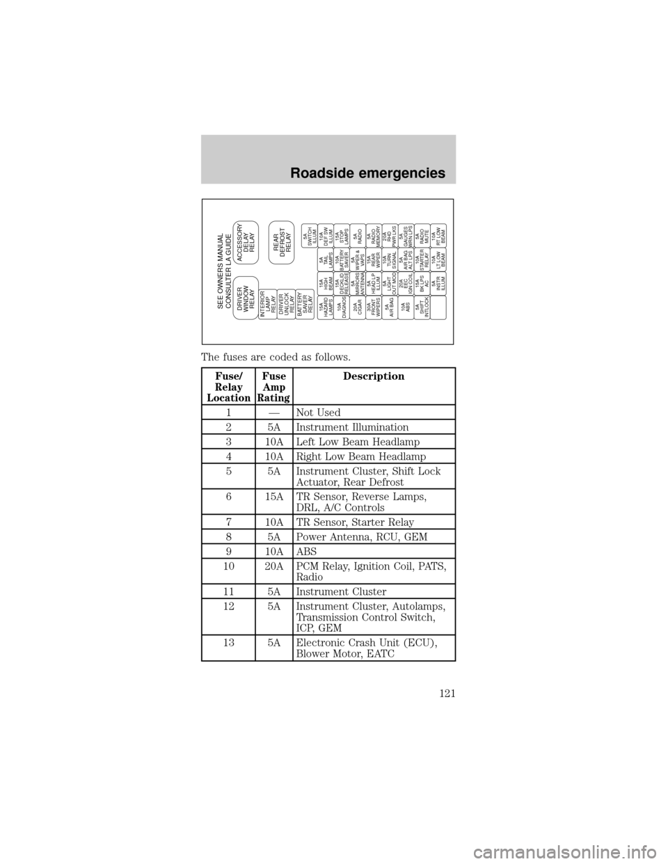
The fuses are coded as follows.
Fuse/
Relay
LocationFuse
Amp
RatingDescription
1 Ð Not Used
2 5A Instrument Illumination
3 10A Left Low Beam Headlamp
4 10A Right Low Beam Headlamp
5 5A Instrument Cluster, Shift Lock
Actuator, Rear Defrost
6 15A TR Sensor, Reverse Lamps,
DRL, A/C Controls
7 10A TR Sensor, Starter Relay
8 5A Power Antenna, RCU, GEM
9 10A ABS
10 20A PCM Relay, Ignition Coil, PATS,
Radio
11 5A Instrument Cluster
12 5A Instrument Cluster, Autolamps,
Transmission Control Switch,
ICP, GEM
13 5A Electronic Crash Unit (ECU),
Blower Motor, EATC
SEE OWNERS MANUAL
CONSULTER LA GUIDEDRIVER
WINDOW
RELAYACCESSORY
DELAY
RELAY
REAR
DEFROST
RELAYINTERIOR
LAMP
RELAY
DRIVER
UNLOCK
RELAY
BATTERY
SAVER
RELAY15A
HAZARD
LAMPS15A
HIGH
BEAM5A
TAIL
LAMPS10A
DEF SW
ILLUM
10A
DIAGNOS15A
DECKLID
RELEASE10A
BATTERY
SAVER15A
STOP
LAMPS
20A
CIGAR5A
MIRRORS
ANTENNA5A
WIPER &
VAPS5A
RADIO
30A
FRONT
WIPERS5A
HEAD LP
ILLUM15A
REAR
WIPER5A
RADIO
MEMORY
5A
AIR BAG5A
LIGHT
OUT MOD10A
TURN
SIGNAL20A
RHD
PWR LKS
10A
ABS20A
EEC
IGN COIL5A
AIR BAG
ALT LPS5A
GAUGES
WRN LPS
5A
SHIFT
INTLOCK15A
BK LPS
AC10A
STARTER
RELAY5A
RADIO
MUTE
5A
INSTR
ILLUM10A
LT LOW
BEAM10A
RT LOW
BEAM5A
SWITCH
ILLUM
Roadside emergencies
121
Page 159 of 216

²Avoid getting fuel liquid in your eyes. If fuel is
splashed in the eyes, remove contact lenses (if
worn), flush with water for 15 minutes and seek
medical attention. Failure to seek proper medical
attention could lead to permanent injury.
²Fuels can also be harmful if absorbed through the
skin. If fuel is splashed on the skin and/or
clothing, promptly remove contaminated clothing
and wash skin thoroughly with soap and water.
Repeated or prolonged skin contact with fuel
liquid or vapor causes skin irritation.
²Be particularly careful if you are taking
ªAntabuseº or other forms of disulfiram for the
treatment of alcoholism. Breathing gasoline
vapors, or skin contact could cause an adverse
reaction. In sensitive individuals, serious personal
injury or sickness may result. If fuel is splashed
on the skin, promptly wash skin thoroughly with
soap and water. Consult a physician immediately
if you experience an adverse reaction.
Fuel Filler Cap
Your fuel tank filler cap has an indexed design with
a one-eighth turn on/off feature.
When fueling your vehicle:
1. Turn the engine off.
2. Carefully turn the filler cap counterclockwise 1/8
of a turn until it stops.
3. Pull to remove the cap from the fuel filler pipe.
4. To install the cap, align the tabs on the cap with
the notches on the filler pipe.
5. Turn the filler cap clockwise 1/8 of a turn until it
stops.
If the ªService Engine Soon/Check Engineº indicator
comes on and stays on when you start the engine,
the fuel filler cap may not be properly installed.
Turn off the engine, remove the fuel filler cap and
reinstall it being careful to align the cap properly.
Maintenance and care
159