sensor Mercury Sable 1999 Owner's Manuals
[x] Cancel search | Manufacturer: MERCURY, Model Year: 1999, Model line: Sable, Model: Mercury Sable 1999Pages: 216, PDF Size: 1.33 MB
Page 86 of 216

How does the air bag supplemental restraint
system work?
The air bag SRS is
designed to activate
when the vehicle
sustains sufficient
longitudinal
deceleration sufficient
to cause the sensors to
close an electrical
circuit that initiates air
bag inflation.
The fact that the air bags did not inflate in a
collision does not mean that something is wrong
with the system. Rather, it means the forces were
not of the type sufficient to cause activation. Air
bags are designed to inflate in frontal and
near-frontal collisions, not rollover, side-impact, or
rear-impacts.
The air bags inflate and
deflate rapidly upon
activation. After air bag
deployment, it is
normal to notice a
smoke-like, powdery
residue or smell the
burnt propellant. This
may consist of
cornstarch, talcum
powder (to lubricate
the bag) or sodium
compounds (e.g., baking soda) that result from the
combustion process that inflates the air bag. Small
amounts of sodium hydroxide may be present which
may irritate the skin and eyes, but none of the
residue is toxic.
While the system is designed to help reduce serious
injuries, it may also cause minor burns, abrasions,
swelling or temporary hearing loss. Because air bags
must inflate rapidly and with considerable force,
Seating and safety restraints
86
Page 87 of 216

there is the risk of death or serious injuries such as
fractures, facial and eye injuries or internal injuries,
particularly to occupants who are not properly
restrained or are otherwise out of position at the
time of air bag deployment. Thus, it is extremely
important that occupants be properly restrained as
far away from the air bag module as possible while
maintaining vehicle control.
Several air bag system components get hot
after inflation. Do not touch them after
inflation.
If the air bag is deployed,the air bag will
not function again and must be replaced
immediately.If the air bag is not replaced, the
unrepaired area will increase the risk of injury in a
collision.
The SRS consists of:
²driver and passenger air bag modules (which
include the inflators and air bags),
²one or more impact and safing sensors,
²a readiness light and tone
²and the electrical wiring which connects the
components.
The diagnostic module monitors its own internal
circuits and the supplemental air bag electrical
system warning (including the impact sensors), the
system wiring, the air bag system readiness light, the
air bag back up power and the air bag ignitors.
Determining if the system is operational
The SRS uses a readiness light in the instrument
cluster or a tone to indicate the condition of the
system. Refer to theAir bag readinesssection in
theInstrumentationchapter. Routine maintenance
of the air bag is not required.
Seating and safety restraints
87
Page 121 of 216

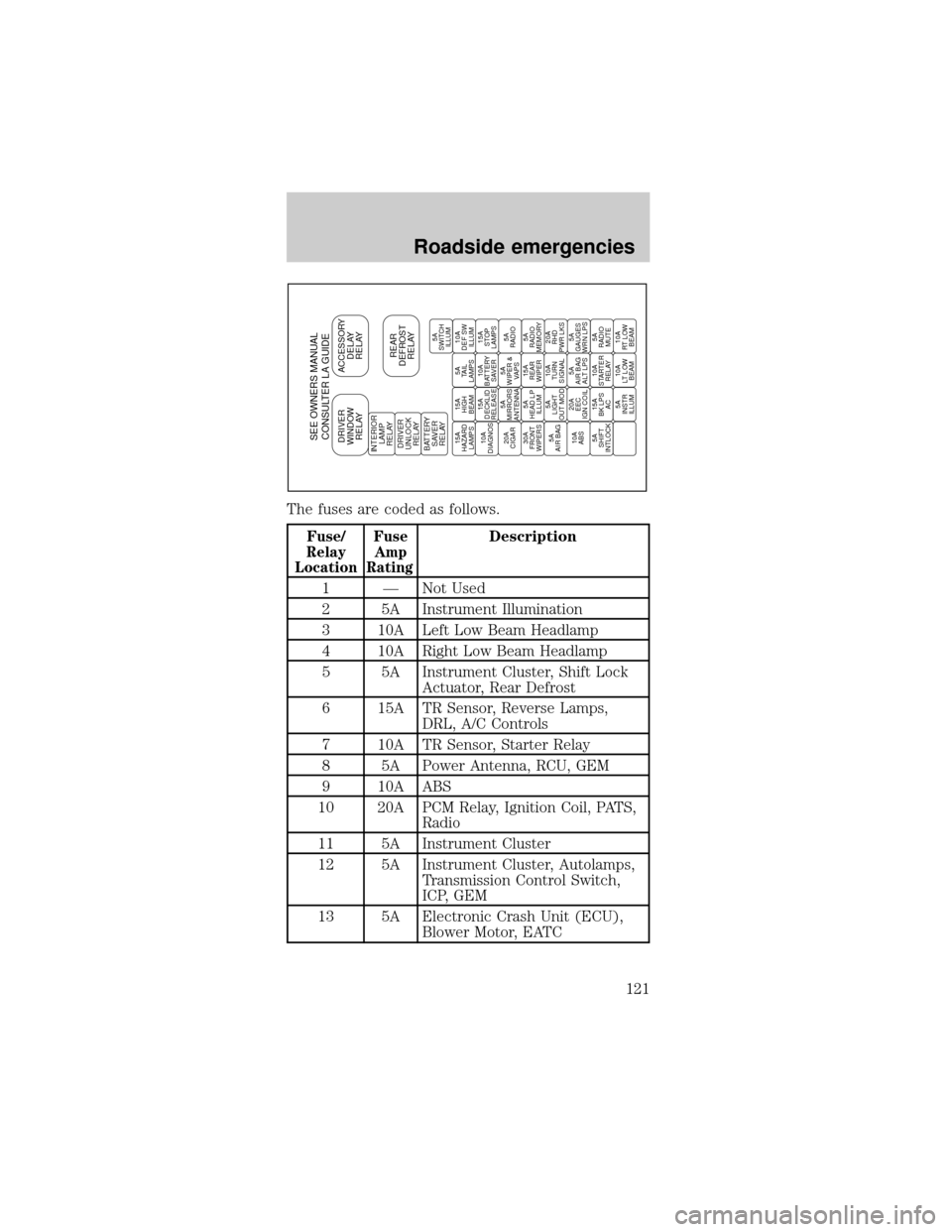
The fuses are coded as follows.
Fuse/
Relay
LocationFuse
Amp
RatingDescription
1 Ð Not Used
2 5A Instrument Illumination
3 10A Left Low Beam Headlamp
4 10A Right Low Beam Headlamp
5 5A Instrument Cluster, Shift Lock
Actuator, Rear Defrost
6 15A TR Sensor, Reverse Lamps,
DRL, A/C Controls
7 10A TR Sensor, Starter Relay
8 5A Power Antenna, RCU, GEM
9 10A ABS
10 20A PCM Relay, Ignition Coil, PATS,
Radio
11 5A Instrument Cluster
12 5A Instrument Cluster, Autolamps,
Transmission Control Switch,
ICP, GEM
13 5A Electronic Crash Unit (ECU),
Blower Motor, EATC
SEE OWNERS MANUAL
CONSULTER LA GUIDEDRIVER
WINDOW
RELAYACCESSORY
DELAY
RELAY
REAR
DEFROST
RELAYINTERIOR
LAMP
RELAY
DRIVER
UNLOCK
RELAY
BATTERY
SAVER
RELAY15A
HAZARD
LAMPS15A
HIGH
BEAM5A
TAIL
LAMPS10A
DEF SW
ILLUM
10A
DIAGNOS15A
DECKLID
RELEASE10A
BATTERY
SAVER15A
STOP
LAMPS
20A
CIGAR5A
MIRRORS
ANTENNA5A
WIPER &
VAPS5A
RADIO
30A
FRONT
WIPERS5A
HEAD LP
ILLUM15A
REAR
WIPER5A
RADIO
MEMORY
5A
AIR BAG5A
LIGHT
OUT MOD10A
TURN
SIGNAL20A
RHD
PWR LKS
10A
ABS20A
EEC
IGN COIL5A
AIR BAG
ALT LPS5A
GAUGES
WRN LPS
5A
SHIFT
INTLOCK15A
BK LPS
AC10A
STARTER
RELAY5A
RADIO
MUTE
5A
INSTR
ILLUM10A
LT LOW
BEAM10A
RT LOW
BEAM5A
SWITCH
ILLUM
Roadside emergencies
121
Page 125 of 216

Fuse/
Relay
LocationFuse
Amp
RatingDescription
18 30A* Anti-Lock Brake Module
19 15A* Horn Relay, Powertrain Control
Module (PCM)
20 15A* Headlamp Switch, Autolamp
Park Relay
21 Ð Not Used
22 30A* Autolamps Relay, Multifunction
Switch, Headlamp Switch
23 Ð Blower Motor Relay
24 Ð Starter Relay
25 Ð A/C Clutch Relay
26 30A* Generator
27 10A* A/C Clutch Relay
28 15A* Heated Oxygen Sensors,
Canister Vent
29 Ð Fuel Pump Relay
30 Ð PCM Relay
31 Ð Low Speed Cooling Fan Relay
32 Ð PCM Diode
33 Ð A/C Clutch Diode
34 Ð Not Used
* Mini Fuses ** Maxi Fuses
Relays
Relays are located in the power distribution box and
should be replaced by qualified technicians.
Roadside emergencies
125