steering wheel Mercury Sable 2000 Owner's Manuals
[x] Cancel search | Manufacturer: MERCURY, Model Year: 2000, Model line: Sable, Model: Mercury Sable 2000Pages: 232, PDF Size: 2.09 MB
Page 43 of 232

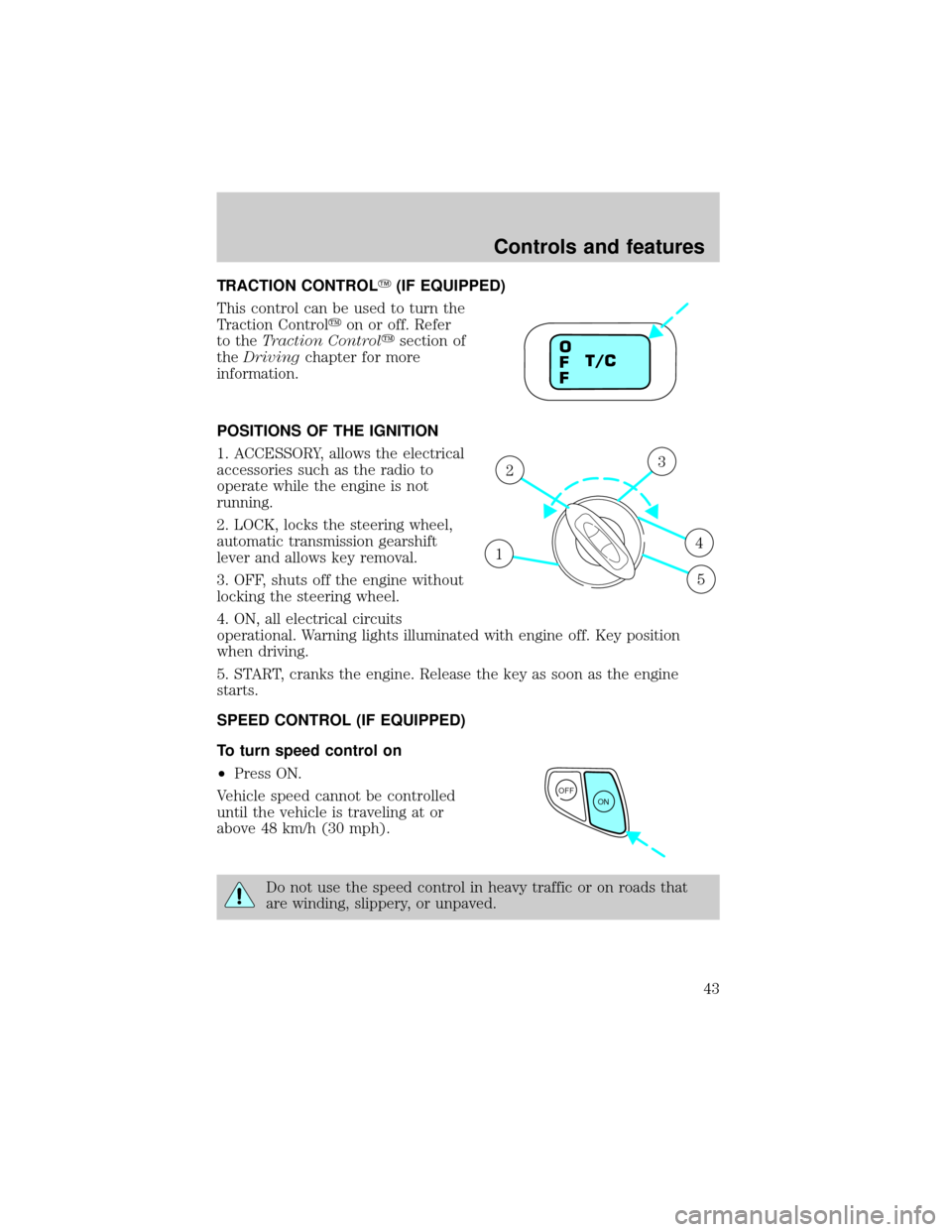
TRACTION CONTROLY(IF EQUIPPED)
This control can be used to turn the
Traction Controlyon or off. Refer
to theTraction Controlysection of
theDrivingchapter for more
information.
POSITIONS OF THE IGNITION
1. ACCESSORY, allows the electrical
accessories such as the radio to
operate while the engine is not
running.
2. LOCK, locks the steering wheel,
automatic transmission gearshift
lever and allows key removal.
3. OFF, shuts off the engine without
locking the steering wheel.
4. ON, all electrical circuits
operational. Warning lights illuminated with engine off. Key position
when driving.
5. START, cranks the engine. Release the key as soon as the engine
starts.
SPEED CONTROL (IF EQUIPPED)
To turn speed control on
²Press ON.
Vehicle speed cannot be controlled
until the vehicle is traveling at or
above 48 km/h (30 mph).
Do not use the speed control in heavy traffic or on roads that
are winding, slippery, or unpaved.
T/C O
F
F
1
23
4
5
OFF
ON
Controls and features
43
Page 48 of 232

TILT STEERING
Pull the tilt steering control toward
you to move the steering wheel up
or down. Hold the control while
adjusting the wheel to the desired
position, then release the control.
Never adjust the steering wheel when the vehicle is moving.
DOME LAMPS AND MAP LAMPS
The front dome lamp is located overhead between the driver and
passenger seats. If the vehicle is equipped with a moon roof, the dome
lamp is located behind the moon roof.
The dome lamp will stay on if the
control is moved to the passenger
side position. When the control is in
the middle position, the lamp will
only come on when a door is
opened. If the control is moved to
the driver's side position, the lamp
will not come on at all.
With the control in the middle position, the dome lamp will illuminate
whenever a front door is opened. If either front door has been opened
from the outside, the lamp will remain on for 25 seconds after the door
is shut. If any other door has been opened from the inside, the lamp will
shut off immediately after the door is closed.
Controls and features
48
Page 56 of 232

TRUNK REMOTE CONTROL
Press the remote trunk release
control on the instrument panel to
the left of the steering wheel.
LIFTGATE (WAGON ONLY)
You can open and close the liftgate and the liftgate window from outside
the vehicle. It cannot be opened from inside the cargo area.
²To open the liftgate window,
unlock the liftgate (with the key,
the power door locks or the
remote entry key fob) and push
the key lock cylinder.
²To open the liftgate, unlock the
liftgate and pull up on the handle
under the license plate lamp
shield.
To lock the liftgate and the liftgate window, press the lock button down
on the inside of the liftgate, use the key, the power door locks, or the
remote entry key fob.
The liftgate and liftgate window should be closed before driving your
vehicle. If not, possible damage may occur to the liftgate lift cylinders
and attaching hardware.
Controls and features
56
Page 78 of 232

SAFETY RESTRAINTS
Personal Safety System
The Personal Safety System provides an improved overall level of frontal
crash protection to front seat occupants and is designed to help further
reduce the risk of air bag-related injuries. The system is able to analyze
different occupant conditions and crash severity before activating the
appropriate safety devices to help better protect a range of occupants in
a variety of frontal crash situations.
Your vehicle's Personal Safety System consists of:
²Driver and passenger dual-stage air bag supplemental restraints. Refer
to theAir bag supplemental restraintssection in this chapter.
²Front safety belts with pretensioners, energy management retractors,
and safety belt usage sensors. Refer to theSafety beltssection in this
chapter.
²Driver's seat position sensor.
²Front crash severity sensor.
²Restraints Control Module (RCM) with impact and safing sensors.
²An indicator light and back-up tone.
²The electrical wiring for the air bags, crash sensor(s), safety belt
pretensioners, front safety belt usage sensors and driver's seat position
sensor.
How does the personal safety system work?
The Personal Safety System uses a collection of sensors to gather
information about the driver's seat position, driver and front outboard
passenger's safety belt usage and accident severity. Then, dual-stage
inflating air bags are combined with safety belt pretensioners and energy
management retractors to help provide enhanced occupant protection in
frontal crashes.
The driver's seat position sensor determines if the seat is fore or aft of a
reference position. Similarly, the safety belt usage sensors determine if
the driver and front outboard passenger safety belts are fastened. These
sensors provide the ability to tailor the air bag deployment based upon
how close the driver's seat is to the steering wheel and whether or not
the safety belts are fastened.
The dual-stage air bags offer the ability to tailor the air bag inflation with
two energy levels. A lower, less forceful energy level is provided for more
Seating and safety restraints
78
Page 108 of 232

2. Make sure the headlamps and vehicle accessories are off.
3. Make sure the parking brake is
set.
4. Make sure the gearshift is in P
(Park).
5. Turn the key to 4 (ON) without
turning the key to 5 (START).
If there is difficulty in turning the
key, firmly rotate the steering wheel
left and right until the key turns
freely. This condition may occur
when:
²front wheels are turned
²front wheel is against the curb
²steering wheel is turned when getting in or out of the vehicle
PRNDD1
3
4
1 2
5
Starting
108
Page 112 of 232

BRAKES
Your service brakes are self-adjusting. Refer to the scheduled
maintenance guide for scheduled maintenance.
Occasional brake noise is normal and often does not indicate a
performance concern with the vehicle's brake system. In normal
operation, automotive brake systems may emit occasional or intermittent
squeal or groan noises when the brakes are applied. Such noises are
usually heard during the first few brake applications in the morning;
however, they may be heard at any time while braking and can be
aggravated by environmental conditions such as cold, heat, moisture,
road dust, salt or mud. If a ªmetal-to-metal,º ªcontinuous grindingº or
ªcontinuous squealº sound is present while braking, the brake linings
may be worn-out and should be inspected by a qualified service
technician.
Anti-lock brake system (ABS) (if equipped)
On vehicles equipped with an anti-lock braking system (ABS), a noise
from the hydraulic pump motor and pulsation in the pedal may be
observed during ABS braking events. Pedal pulsation coupled with noise
while braking under panic conditions or on loose gravel, bumps, wet or
snowy roads is normal and indicates proper functioning of the vehicle's
anti-lock brake system. The ABS performs a self-check after you start
the engine and begin to drive away. A brief mechanical noise may be
heard during this test. This is normal. If a malfunction is found, the ABS
warning light will come on. If the vehicle has continuous vibration or
shudder in the steering wheel while braking, the vehicle should be
inspected by a qualified service technician.
The ABS operates by detecting the
onset of wheel lockup during brake
applications and compensates for
this tendency. The wheels are
prevented from locking even when
the brakes are firmly applied. The
accompanying illustration depicts
the advantage of an ABS equipped
vehicle (on bottom) to a non-ABS
equipped vehicle (on top) during hard braking with loss of front braking
traction.
Driving
112
Page 116 of 232

During Traction Controlyoperation,
the traction control active light will
illuminate, you may hear an electric
motor type of sound coming from
the engine compartment and the
engine will not ªrev-upº when you push further on the accelerator. This
is normal system behavior.
The Traction Controlyon/off switch, located on the right side of the
instrument cluster, illuminates OFF when the system is turned OFF. The
Traction Controlysystem will revert to the ON position every time the
ignition is turned OFF and ON.
If you should become stuck in snow or ice or on a very slippery road
surface, try switching the Traction Controlysystem off. This may allow
excess wheel spin to ªdigº the vehicle out and enable a successful
ªrockingº maneuver.
If a system fault is detected the traction control active light will
illuminate, the Traction Controlyon/off switch will not toggle on and off,
and your vehicle should be serviced as soon as possible.
STEERING
Your vehicle is equipped with power steering. Power steering uses energy
from the engine to help steer the vehicle.
To prevent damage to the power steering pump:
²Never hold the steering wheel to the extreme right or the extreme left
for more than a few seconds when the engine is running.
²Do not operate the vehicle with a low power steering pump fluid level
(below the MIN mark on the reservoir).
If the power steering system breaks down (or if the engine is turned
off), you can steer the vehicle manually, but it takes more effort.
If the steering wanders or pulls, the condition could be caused by any of
the following:
²underinflated tire(s) on any wheel(s)
²high crown in center of road
²high crosswinds
²wheels out of alignment
²loose or worn components in steering linkage
Driving
116
Page 133 of 232

Passenger compartment fuse panel
The fuse panel is located below and to the left of the steering wheel by
the brake pedal. Remove the panel cover to access the fuses.
To remove a fuse use the fuse puller tool provided on the fuse panel
cover.
The fuses are coded as follows.
Fuse/Relay
LocationFuse Amp
RatingPassenger Compartment
Fuse Panel Description
1 Ð Accessory Delay Relay
2 Ð Driver One Touch Down Relay
3 Ð Blower Motor Relay
4 Ð Flasher Relay
5 Ð Not Used
6 Ð Not Used
7 40A Rear Defrost Grid Feed
8 40A Blower Motor
9 Ð Rear Defrost Relay
10 30A Power Seats, Delayed Accessory, Adjustable
Pedals
11 15A Integrated Control Panel (ICP), Rear
Washer Wiper Control, Front Washer, Cell
Phone, Passenger Switch Illumination,
GEM, Rear Wiper Motor
12 10A Heated Mirrors, Rear Defrost Switch
12
34
56
78
9
10
11 1213 14
15
16 1718
19 2021 22
2324
2526
27 2829
30
32 33
35
3637
38
39 40
41
42
PULL TAB
TO RELEASE SEE OWNERS MANUAL
CONSULTER LA GUIDE
Roadside emergencies
133
Page 137 of 232

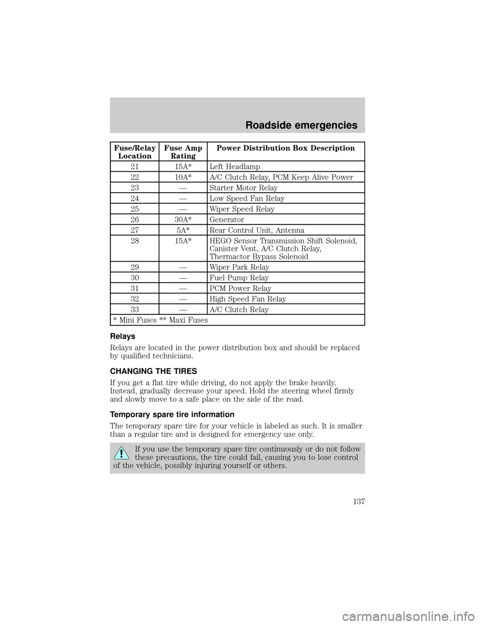
Fuse/Relay
LocationFuse Amp
RatingPower Distribution Box Description
21 15A* Left Headlamp
22 10A* A/C Clutch Relay, PCM Keep Alive Power
23 Ð Starter Motor Relay
24 Ð Low Speed Fan Relay
25 Ð Wiper Speed Relay
26 30A* Generator
27 5A* Rear Control Unit, Antenna
28 15A* HEGO Sensor Transmission Shift Solenoid,
Canister Vent, A/C Clutch Relay,
Thermactor Bypass Solenoid
29 Ð Wiper Park Relay
30 Ð Fuel Pump Relay
31 Ð PCM Power Relay
32 Ð High Speed Fan Relay
33 Ð A/C Clutch Relay
* Mini Fuses ** Maxi Fuses
Relays
Relays are located in the power distribution box and should be replaced
by qualified technicians.
CHANGING THE TIRES
If you get a flat tire while driving, do not apply the brake heavily.
Instead, gradually decrease your speed. Hold the steering wheel firmly
and slowly move to a safe place on the side of the road.
Temporary spare tire information
The temporary spare tire for your vehicle is labeled as such. It is smaller
than a regular tire and is designed for emergency use only.
If you use the temporary spare tire continuously or do not follow
these precautions, the tire could fail, causing you to lose control
of the vehicle, possibly injuring yourself or others.
Roadside emergencies
137
Page 161 of 232

Vehicles driven year-round in non-extreme climates should use a 50/50
mixture of engine coolant and distilled water for optimum cooling system
and engine protection.
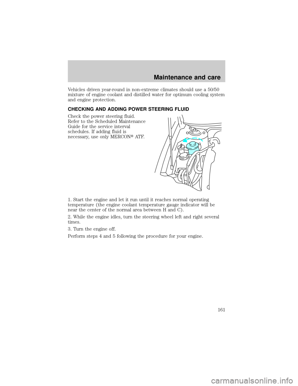
CHECKING AND ADDING POWER STEERING FLUID
Check the power steering fluid.
Refer to the Scheduled Maintenance
Guide for the service interval
schedules. If adding fluid is
necessary, use only MERCONtAT F.
1. Start the engine and let it run until it reaches normal operating
temperature (the engine coolant temperature gauge indicator will be
near the center of the normal area between H and C).
2. While the engine idles, turn the steering wheel left and right several
times.
3. Turn the engine off.
Perform steps 4 and 5 following the procedure for your engine.
Maintenance and care
161