engine Mercury Sable 2001 s Owner's Guide
[x] Cancel search | Manufacturer: MERCURY, Model Year: 2001, Model line: Sable, Model: Mercury Sable 2001Pages: 240, PDF Size: 2.22 MB
Page 130 of 240

Once through the water, always try the brakes. Wet brakes do not stop
the vehicle as effectively as dry brakes. Drying can be improved by
moving your vehicle slowly while applying light pressure on the brake
pedal.
Driving through deep water where the transmission vent tube is
submerged may allow water into the transmission and cause
internal transmission damage.
TRAILER TOWING
Your vehicle is classified as a light duty towing vehicle. The amount of
weight you can safely tow depends on the type of engine you have in
your vehicle. Your vehicle does not come from the factory fully equipped
to tow. No towing packages are available through Ford or
Mercury/Lincoln dealers. Do not tow a trailer until your vehicle has been
driven at least 800 km (500 miles). If towing with a station wagon, inflate
the rear tires to 35 psi.
Towing a trailer places an additional load on your vehicle's engine,
transaxle, brakes, tires and suspension. Inspect these components
carefully after towing.
In order to identify your vehicle's engine, refer toIdentifying
components in the engine compartmentin the Maintenance and Care
chapter.
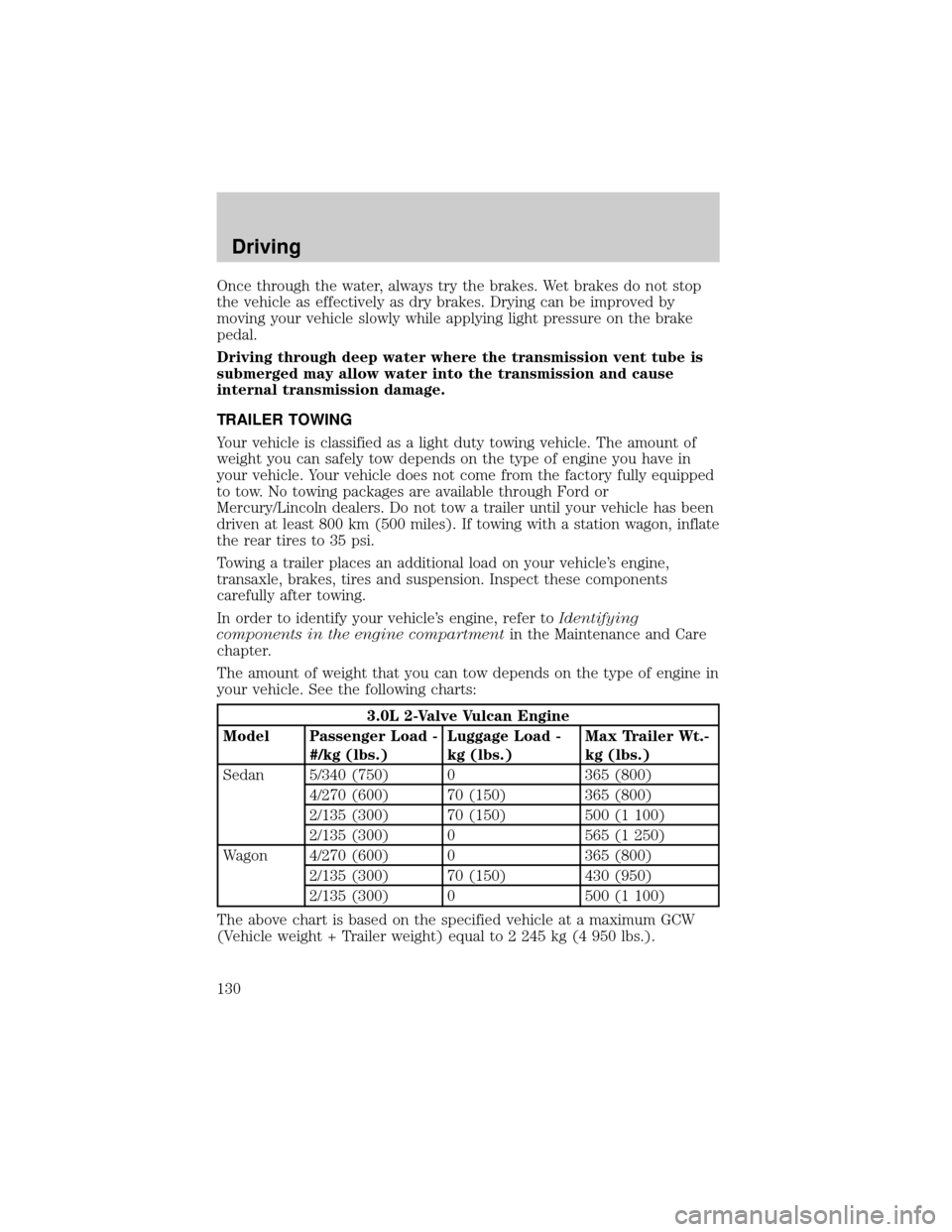
The amount of weight that you can tow depends on the type of engine in
your vehicle. See the following charts:
3.0L 2-Valve Vulcan Engine
Model Passenger Load -
#/kg (lbs.)Luggage Load -
kg (lbs.)Max Trailer Wt.-
kg (lbs.)
Sedan 5/340 (750) 0 365 (800)
4/270 (600) 70 (150) 365 (800)
2/135 (300) 70 (150) 500 (1 100)
2/135 (300) 0 565 (1 250)
Wagon 4/270 (600) 0 365 (800)
2/135 (300) 70 (150) 430 (950)
2/135 (300) 0 500 (1 100)
The above chart is based on the specified vehicle at a maximum GCW
(Vehicle weight + Trailer weight) equal to 2 245 kg (4 950 lbs.).
Driving
130
Page 131 of 240

3.0L 4-Valve Duratec Engine
Model Passenger Load -
#/kg (lbs.)Luggage Load -
kg (lbs.)Max Trailer Wt.-
kg (lbs.)
Sedan 5/340 (750) 0 590 (1 300)
2/135 (300) 70 (150) 725 (1 600)
2/135 (300) 0 795 (1 750)
Wagon 5/340 (750) 70 (150) 455 (1 000)
2/135 (300) 70 (150) 660 (1 450)
2/135 (300) 0 725 (1 600)
The above chart is based on the specified vehicle at a maximum GCW
(Vehicle weight + Trailer weight) equal to 2 470 kg (5 450 lbs.).
Do not exceed the GVWR or the GAWR specified on the
certification label.
Towing trailers beyond the maximum recommended gross trailer
weight exceeds the limit of the vehicle and could result in
engine damage, transaxle damage, structural damage, loss of control,
and personal injury.
Preparing to tow
Use the proper equipment for towing a trailer, and make sure it is
properly attached to your vehicle. See your dealer or a reliable trailer
dealer if you require assistance.
Hitches
Do not use hitches that clamp onto the vehicle bumper. Use a load
carrying hitch. You must distribute the load in your trailer so that 10% of
the total weight of the trailer is on the tongue.
Safety chains
Always connect the trailer's safety chains to the frame or hook retainers
of the vehicle hitch. To connect the trailer's safety chains, cross the
chains under the trailer tongue and allow slack for turning corners.
If you use a rental trailer, follow the instructions that the rental agency
gives to you.
Do not attach safety chains to the bumper.
Driving
131
Page 133 of 240

²The trailer tongue weight should be 10% of the loaded trailer weight.
²After you have traveled 80 km (50 miles), thoroughly check your
hitch, electrical connections and trailer wheel lug nuts.
²When stopped in traffic for long periods of time in hot weather, place
the gearshift in P (Park) and increase idle speed. This aids engine
cooling and air conditioner efficiency.
²Vehicles with trailers should not be parked on a grade. If you must
park on a grade, place wheel chocks under the trailer's wheels.
Recreational towing
Follow these guidelines for your specific powertrain combination to tow
your vehicle with all four wheels on the ground (such as behind a
recreational vehicle).
These guidelines are designed to ensure that your transmission is not
damaged due to insufficient lubrication.
All Front Wheel Drive (FWD) vehicles
An example of recreational towing is towing your vehicle behind a
Motorhome. The following recreational towing guidelines are designed to
ensure that your transmission is not damaged. It is not recommended to
tow front wheel drive vehicles with the front drive wheels on the ground.
It is recommended to tow your vehicle with the drive wheels on a dolly
or two wheel car hauling trailer.
In case of a roadside emergency with a disabled vehicle (without access
to wheel dollies, car hauling trailer or flatbed transport vehicle) your
vehicle can be flat towed (all wheels on the ground) under the following
conditions:
²Place the transmission in N (Neutral).
²Maximum speed is 56 km/h (35 mph).
²Maximum distance is 80 km (50 miles).
Driving
133
Page 136 of 240

Roadside coverage beyond basic warranty
In the United States, you may purchase additional roadside assistance
coverage beyond this period through the Ford Auto Club by contacting
your Ford or Lincoln Mercury dealer.
Similarly in Canada, you may purchase additional coverage beyond the
basic coverage period by consulting the Ford Roadside Assistance Club
brochure or by calling 1±877±294±CLUB (1±877±294±2582).
HAZARD FLASHER
Use only in an emergency to warn traffic of vehicle breakdown,
approaching danger, etc. The hazard flashers can be operated when the
ignition is off.
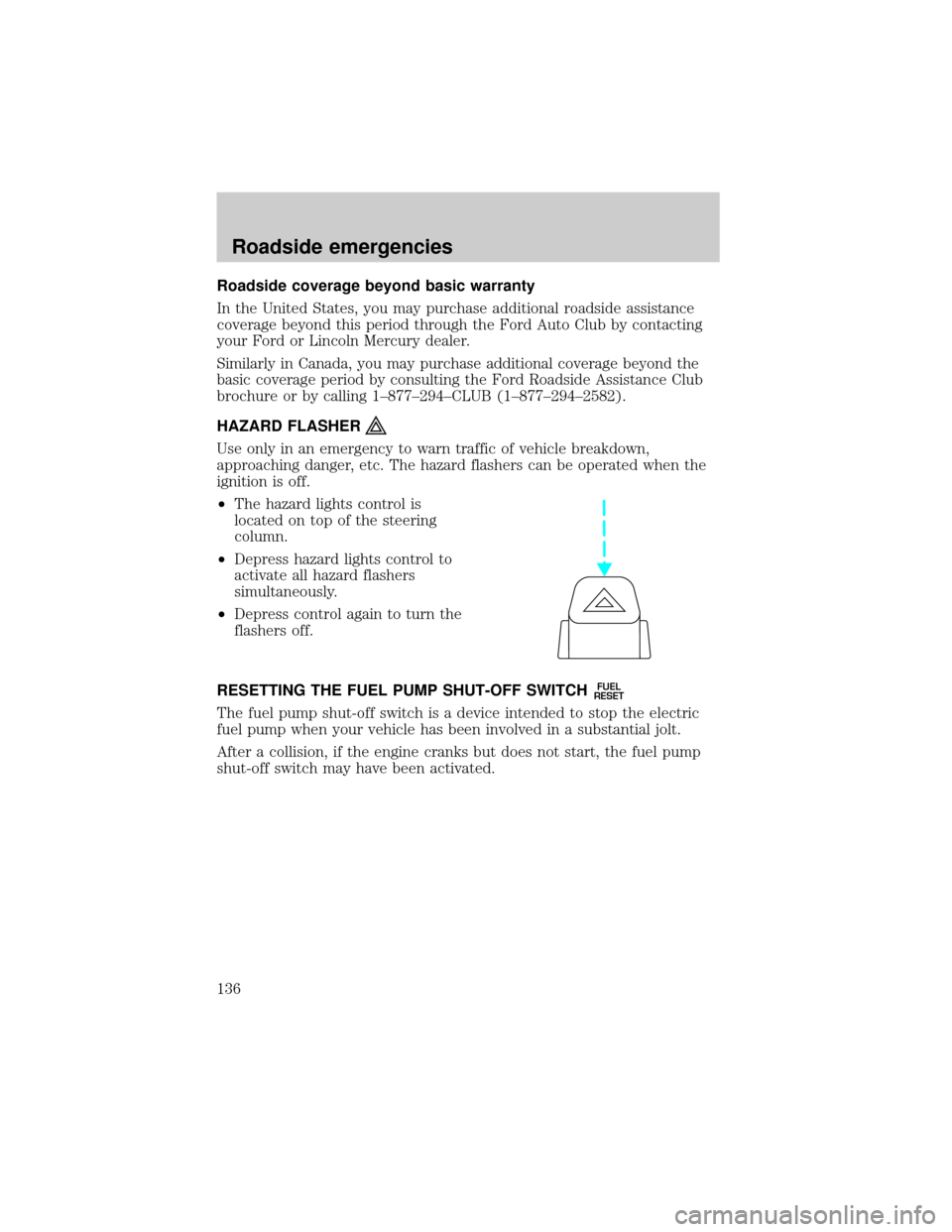
²The hazard lights control is
located on top of the steering
column.
²Depress hazard lights control to
activate all hazard flashers
simultaneously.
²Depress control again to turn the
flashers off.
RESETTING THE FUEL PUMP SHUT-OFF SWITCH
FUEL
RESET
The fuel pump shut-off switch is a device intended to stop the electric
fuel pump when your vehicle has been involved in a substantial jolt.
After a collision, if the engine cranks but does not start, the fuel pump
shut-off switch may have been activated.
Roadside emergencies
136
Page 141 of 240

Fuse/Relay
LocationFuse Amp
RatingPassenger Compartment
Fuse Panel Description
37 15A Transmission Position Switch
38 5A GEM Park Neutral Switch
39 Ð Not Used
40 Ð Not Used
41 Ð Not Used
42 Ð Not Used
Power distribution box
The power distribution box is
located in the engine compartment.
The power distribution box contains
high-current fuses that protect your
vehicle's main electrical systems
from overloads.
Always disconnect the battery before servicing high current
fuses.
Always replace the cover to the Power Distribution Box before
reconnecting the battery or refilling fluid reservoirs.
If the battery has been disconnected and reconnected, refer to the
Batterysection of theMaintenance and carechapter.
Roadside emergencies
141
Page 144 of 240

When driving with the temporary spare tiredo not:
²exceed 80 km/h (50 mph) under any circumstances
²load the vehicle beyond maximum vehicle load rating listed on the
Safety Compliance Label
²tow a trailer
²use tire chains
²drive through an automatic car wash, because of the vehicle's reduced
ground clearance
²try to repair the temporary spare tire or remove it from its wheel
²use the wheel for any other type of vehicle
Tire change procedure
1. Park on a level surface, activate hazard flashers and set parking brake.
When one of the front wheels is off the ground, the transaxle
alone will not prevent the vehicle from moving or slipping off the
jack, even if the vehicle is in P (Park).
To prevent the vehicle from moving when you change a tire, be
sure the parking brake is set, then block (in both directions) the
wheel that is diagonally opposite (other side and end of the vehicle) to
the tire being changed.
If the vehicle slips off the jack, you or someone else could be
seriously injured.
2. Place gearshift lever in P (Park),
turn engine OFF, block the
diagonally opposite wheel, then
remove the spare tire, jack and lug
wrench.
Roadside emergencies
144
Page 148 of 240

2. Do not disconnect the battery of the disabled vehicle as this could
damage the vehicle's electrical system.
3.
Park the booster vehicle close to the hood of the disabled vehicle
making sure the two vehiclesdo nottouch. Set the parking brake on both
vehicles and stay clear of the engine cooling fan and other moving parts.
4. Check all battery terminals and remove any excessive corrosion before
you attach the battery cables. Ensure that vent caps are tight and level.
5. Turn the heater fan on in both vehicles to protect any electrical
surges. Turn all other accessories off.
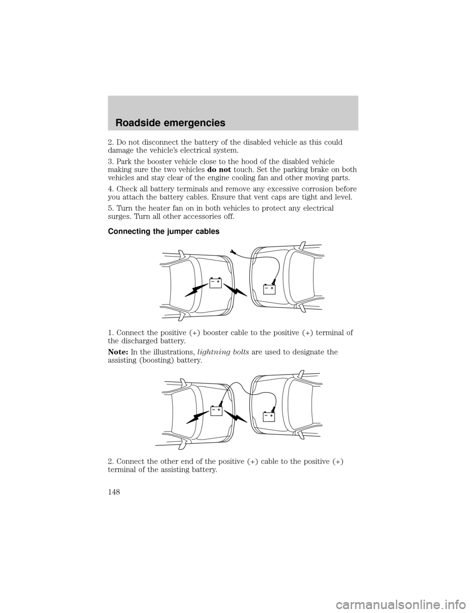
Connecting the jumper cables
1. Connect the positive (+) booster cable to the positive (+) terminal of
the discharged battery.
Note:In the illustrations,lightning boltsare used to designate the
assisting (boosting) battery.
2. Connect the other end of the positive (+) cable to the positive (+)
terminal of the assisting battery.
+–+–
+–+–
Roadside emergencies
148
Page 149 of 240

3. Connect the negative (-) cable to the negative (-) terminal of the
assisting battery.
4. Make the final connection of the negative (-) cable. Make the
connection to an exposed metal part of the stalled vehicle's engine, away
from the battery and the carburetor/fuel injection system.Do notuse
fuel lines, engine rocker covers or the intake manifold asgrounding
points.
Do not connect the end of the second cable to the negative (-)
terminal of the battery to be jumped. A spark may cause an
explosion of the gases that surround the battery.
5. Ensure that the cables are clear of fan blades, belts, moving parts of
both engines, or any fuel delivery system parts.
+–+–
+–+–
Roadside emergencies
149
Page 150 of 240

Jump starting
1. Start the engine of the booster vehicle and run the engine at
moderately increased speed.
2. Start the engine of the disabled vehicle.
3. Once the disabled vehicle has been started, run both engines for an
additional three minutes before disconnecting the jumper cables.
Removing the jumper cables
Remove the jumper cables in the reverse order that they were
connected.
1. Remove the jumper cable from thegroundmetal surface.
2. Remove the jumper cable on the negative (-) connection of the
booster vehicle's battery.
+–+–
+–+–
Roadside emergencies
150
Page 151 of 240

3. Remove the jumper cable from the positive (+) terminal of the booster
vehicle's battery.
4. Remove the jumper cable from the positive (+) terminal of the
disabled vehicle's battery.
After the disabled vehicle has been started and the jumper cables
removed, allow it to idle for several minutes so the engine computer can
relearnits idle conditions.
+–+–
+–+–
Roadside emergencies
151