engine Mercury Villager 1999 s Owner's Guide
[x] Cancel search | Manufacturer: MERCURY, Model Year: 1999, Model line: Villager, Model: Mercury Villager 1999Pages: 264, PDF Size: 2.19 MB
Page 165 of 264
VEHICLE LOADING
Before loading a vehicle, familiarize yourself with the following terms:
²Base Curb Weight: Weight of the vehicle including any standard
equipment, fluids, lubricants, etc. It does not include passengers or
aftermarket equipment.
²Payload: Combined maximum allowable weight of cargo, passengers
and optional equipment. The payload equals the gross vehicle weight
rating minus base curb weight.
²GVW (Gross Vehicle Weight): Base curb weight plus payload
weight. The GVW is not a limit or a specification.
²GVWR (Gross Vehicle Weight Rating): Maximum total weight of
the base vehicle, passengers, optional equipment and cargo. The
GVWR is specific to each vehicle and is listed on the Safety
Compliance Label on the driver's door pillar.
²GAWR (Gross Axle Weight Rating): Carrying capacity for each
axle system. The GAWR is specific to each vehicle and is listed on the
Safety Compliance Label on the driver's door pillar.
²GCWR (Gross Combined Weight Rating): Maximum combined
weight of towing vehicle (including passengers and cargo) and the
trailer. The GCWR indicates the maximum loaded weight that the
vehicle is designed to tow.
²Maximum Trailer Weight Rating: Maximum weight of a trailer the
vehicle is permitted to tow. The maximum trailer weight rating is
determined by subtracting the vehicle curb weight for each
engine/transmission combination, any required option weight for trailer
towing and the weight of the driver from the GCWR for the towing
vehicle.
²Maximum Trailer Weight: maximum weight of a trailer the loaded
vehicle (including passengers and cargo) is permitted to tow. It is
determined by subtracting the weight of the loaded trailer towing
vehicle from the GCWR for the towing vehicle.
²Trailer Weight Range: Specified weight range that the trailer must
fall within that ranges from zero to the maximum trailer weight rating.
Do not exceed the GVWR or the GAWR specified on the
certification label.
Driving
165
Page 166 of 264
Do not use replacement tires with lower load carrying capacities than the
originals because they may lower the vehicle's GVWR and GAWR
limitations. Replacement tires with a higher limit than the originals do
not increase the GVWR and GAWR limitations.
The Certification Label, found on the inside pillar of the driver's door,
lists several important vehicle weight rating limitations. Before adding
any additional equipment, refer to these limitations. If you are adding
weight to the front of your vehicle, (potentially including weight added
to the cab), the weight added should not exceed the Front Axle Reserve
Capacity (FARC). Additional frontal weight may be added to the front
axle reserve capacity provided you limit your payload in other ways (i.e.
restrict the number of passengers or amount of cargo carried).
You may add equipment throughout your vehicle if the total weight
added is equal to or less than the Total Axle Reserve Capacity (TARC)
weight. You should NEVER exceed the Total Axle Reserve Capacity.
Always ensure that the weight of passengers, cargo and equipment being
carried is within the weight limitations that have been established for
your vehicle including both Gross Vehicle Weight and Front and Rear
Gross Axle Weight Rating limits. Under no circumstance should these
limitations be exceeded. Exceeding any vehicle weight rating limitation
could result in serious damage to the vehicle and/or personal injury.
TRAILER TOWING
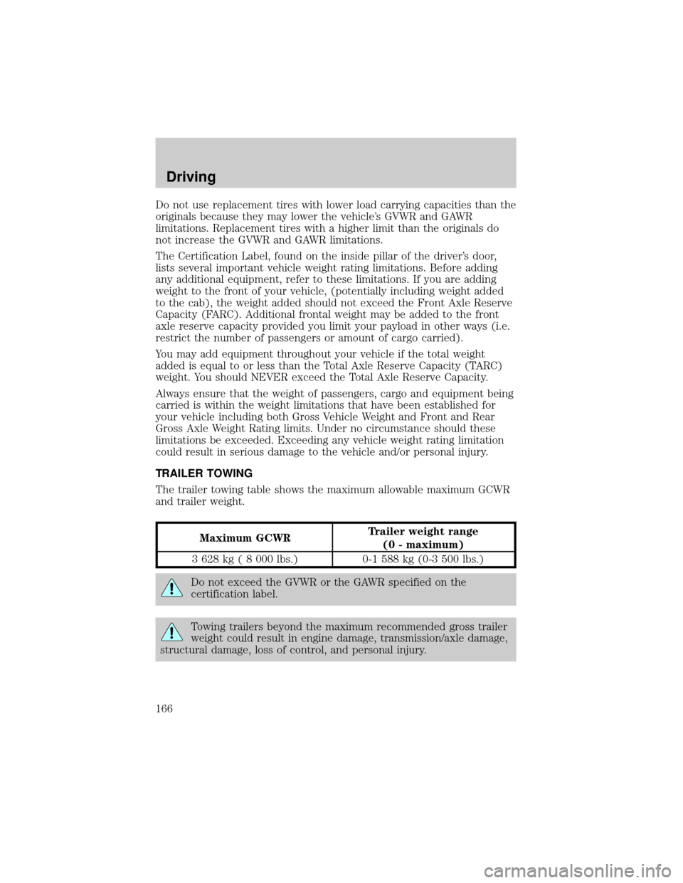
The trailer towing table shows the maximum allowable maximum GCWR
and trailer weight.
Maximum GCWRTrailer weight range
(0 - maximum)
3 628 kg ( 8 000 lbs.) 0-1 588 kg (0-3 500 lbs.)
Do not exceed the GVWR or the GAWR specified on the
certification label.
Towing trailers beyond the maximum recommended gross trailer
weight could result in engine damage, transmission/axle damage,
structural damage, loss of control, and personal injury.
Driving
166
Page 167 of 264

The optional Trailer Tow Prep Package is recommended for towing of
any trailer since it provides a heavy duty battery, conventional size spare
tire and wiring.
Trailer towing puts additional loads on your vehicle's engine,
transmission, axle, brakes, tires, and suspension. For your safety and to
maximize vehicle performance, be sure to use the proper equipment
while towing.
Follow these guidelines to ensure safe towing procedure:
²Stay within your vehicle's load limits. If exceeded, cargo should be
removed from the trailer and/or the vehicle until all weights are within
specified limits.
²Thoroughly prepare your vehicle for towing. Refer toPreparing to
towin this chapter.
²Use extra caution when driving while trailer towing. Refer toDriving
while you towin this chapter.
²Service your vehicle more frequently if you tow a trailer. Refer to the
severe duty schedule in the Scheduled Maintenance Guide.
²Do not tow a trailer until your vehicle has been driven at least 800 km
(500 miles).
²Refer to the instructions included with towing accessories for the
proper installation and adjustment specifications.
Trailer Tow Prep Package (if equipped)
The trailer tow prep package on your vehicle (if equipped) includes:
²Heavy duty battery
²Conventional size spare tire
²Trailer tow module and jumper harness
Using the jumper harness (if equipped)
²Remove the connector cap from the vehicle harness located behind
the rear bumper. Store the connector cap in the glove box for
reinstallation.
²Connect the tow harness to the vehicle harness located behind the
rear bumper.
²Connect the tow harness connector (SAE J1239) to your trailer.
²Confirm the proper vehicle and trailer stop/turn lamp operation.
Driving
167
Page 169 of 264

Trailer lamps
Trailer lamps are required on most towed vehicles. Make sure your
trailer lamps conform to local and Federal regulations. See your dealer or
trailer rental agency for proper instructions and equipment for hooking
up trailer lamps.
Driving while you tow
Do not drive faster than 88 km/h (55 mph) when towing a trailer.
Speed control may shut off if you are towing on long, steep grades.
When towing a trailer:
²Use a lower gear when towing up or down steep hills. This will
eliminate excessive downshifting and upshifting for optimum fuel
economy and transaxle cooling.
²Anticipate stops and brake gradually.
Exceeding the GCWR rating may cause internal transaxle damage
and void your warranty coverage.
Servicing after towing
If you tow a trailer for long distances, your vehicle will require more
frequent service intervals. Refer to your Scheduled Maintenance Guide
for more information.
Trailer towing tips
²Practice turning, stopping and backing up in an area before starting on
a trip to get the feel of the vehicle trailer combination. When turning,
make wider turns so the trailer wheels will clear curbs and other
obstacles.
²Allow more distance for stopping with a trailer attached.
²The trailer tongue weight should be 10% of the loaded trailer weight.
²After you have traveled 80 km (50 miles), thoroughly check your
hitch, electrical connections and trailer wheel lug nuts.
²When stopped in traffic for long periods of time in hot weather, place
the gearshift in P (Park) and increase idle speed. This aids engine
cooling and air conditioner efficiency.
²Vehicles with trailers should not be parked on a grade. If you must
park on a grade, place wheel chocks under the trailer's wheels.
Driving
169
Page 171 of 264
HAZARD FLASHER
Use only in an emergency to warn traffic of vehicle breakdown,
approaching danger, etc. The hazard flashers can be operated when the
ignition is off.
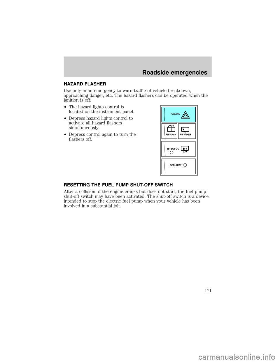
²The hazard lights control is
located on the instrument panel.
²Depress hazard lights control to
activate all hazard flashers
simultaneously.
²Depress control again to turn the
flashers off.
RESETTING THE FUEL PUMP SHUT-OFF SWITCH
After a collision, if the engine cranks but does not start, the fuel pump
shut-off switch may have been activated. The shut-off switch is a device
intended to stop the electric fuel pump when your vehicle has been
involved in a substantial jolt.
SECURITYHAZARD
RR DEFOGRR WIPER RR WASH
Roadside emergencies
171
Page 176 of 264
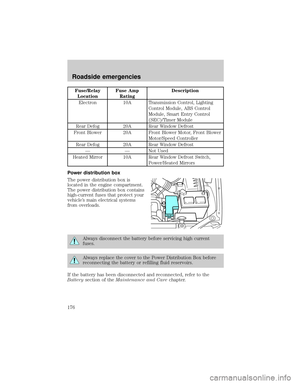
Fuse/Relay
LocationFuse Amp
RatingDescription
Electron 10A Transmission Control, Lighting
Control Module, ABS Control
Module, Smart Entry Control
(SEC)/Timer Module
Rear Defog 20A Rear Window Defrost
Front Blower 20A Front Blower Motor, Front Blower
Motor/Speed Controller
Rear Defog 20A Rear Window Defrost
Ð Ð Not Used
Heated Mirror 10A Rear Window Defrost Switch,
Power/Heated Mirrors
Power distribution box
The power distribution box is
located in the engine compartment.
The power distribution box contains
high-current fuses that protect your
vehicle's main electrical systems
from overloads.
Always disconnect the battery before servicing high current
fuses.
Always replace the cover to the Power Distribution Box before
reconnecting the battery or refilling fluid reservoirs.
If the battery has been disconnected and reconnected, refer to the
Batterysection of theMaintenance and Carechapter.
Roadside emergencies
176
Page 179 of 264
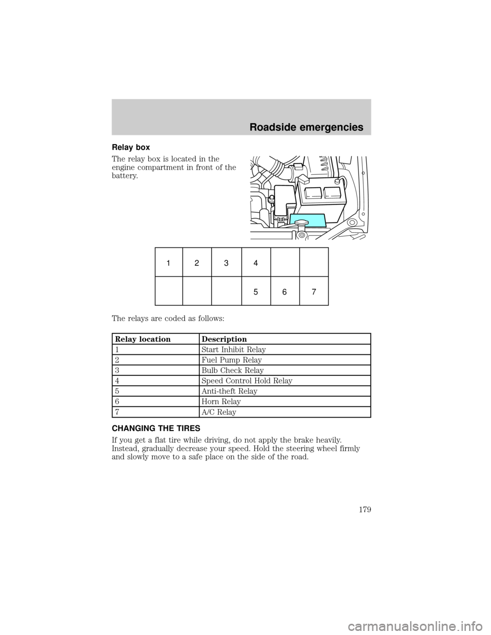
Relay box
The relay box is located in the
engine compartment in front of the
battery.
The relays are coded as follows:
Relay location Description
1 Start Inhibit Relay
2 Fuel Pump Relay
3 Bulb Check Relay
4 Speed Control Hold Relay
5 Anti-theft Relay
6 Horn Relay
7 A/C Relay
CHANGING THE TIRES
If you get a flat tire while driving, do not apply the brake heavily.
Instead, gradually decrease your speed. Hold the steering wheel firmly
and slowly move to a safe place on the side of the road.
1234
56 7
Roadside emergencies
179
Page 183 of 264
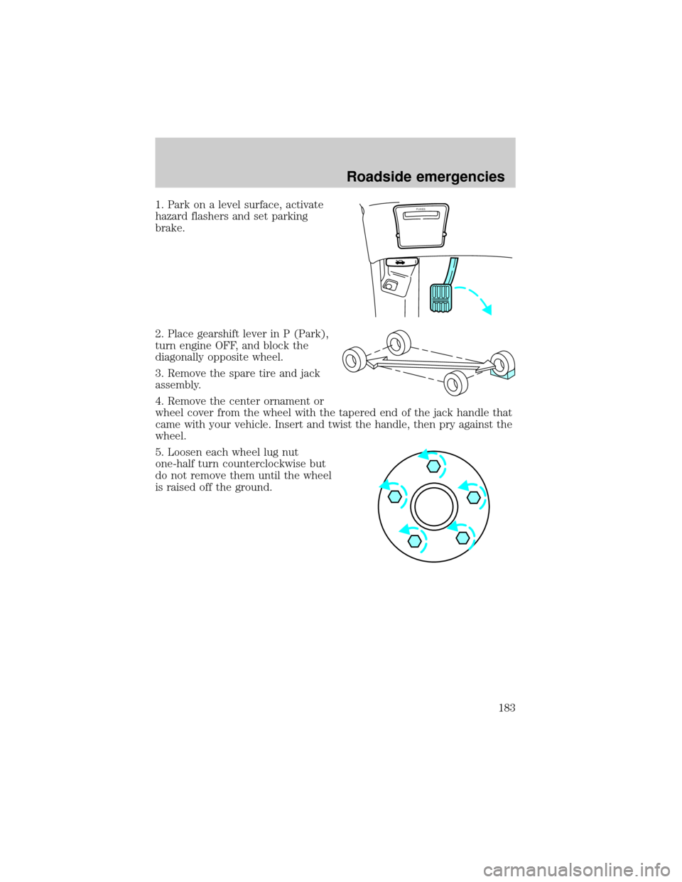
1. Park on a level surface, activate
hazard flashers and set parking
brake.
2. Place gearshift lever in P (Park),
turn engine OFF, and block the
diagonally opposite wheel.
3. Remove the spare tire and jack
assembly.
4. Remove the center ornament or
wheel cover from the wheel with the tapered end of the jack handle that
came with your vehicle. Insert and twist the handle, then pry against the
wheel.
5. Loosen each wheel lug nut
one-half turn counterclockwise but
do not remove them until the wheel
is raised off the ground.FUSES
Roadside emergencies
183
Page 184 of 264
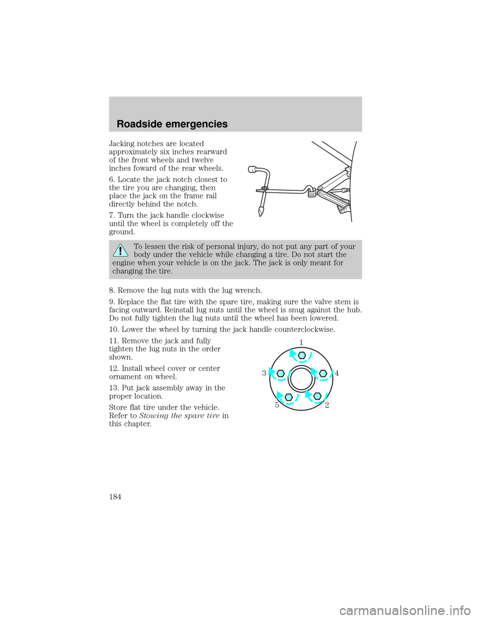
Jacking notches are located
approximately six inches rearward
of the front wheels and twelve
inches foward of the rear wheels.
6. Locate the jack notch closest to
the tire you are changing, then
place the jack on the frame rail
directly behind the notch.
7. Turn the jack handle clockwise
until the wheel is completely off the
ground.
To lessen the risk of personal injury, do not put any part of your
body under the vehicle while changing a tire. Do not start the
engine when your vehicle is on the jack. The jack is only meant for
changing the tire.
8. Remove the lug nuts with the lug wrench.
9. Replace the flat tire with the spare tire, making sure the valve stem is
facing outward. Reinstall lug nuts until the wheel is snug against the hub.
Do not fully tighten the lug nuts until the wheel has been lowered.
10. Lower the wheel by turning the jack handle counterclockwise.
11. Remove the jack and fully
tighten the lug nuts in the order
shown.
12. Install wheel cover or center
ornament on wheel.
13. Put jack assembly away in the
proper location.
Store flat tire under the vehicle.
Refer toStowing the spare tirein
this chapter.
1
4 3
2 5
Roadside emergencies
184
Page 185 of 264
JUMP STARTING YOUR VEHICLE
The gases around the battery can explode if exposed to flames,
sparks, or lit cigarettes. An explosion could result in injury or
vehicle damage.
Do not push start your vehicle. You could damage the catalytic
converter.
Batteries contain sulfuric acid which can burn skin, eyes, and
clothing, if contacted.
Do not attempt to push start your vehicle. Automatic
transmissions do not have push-start capability.
Preparing your vehicle
1.Use only a 12±volt supply to start your vehicle.
2. Do not disconnect the battery of the disabled vehicle as this could
damage the vehicle's electrical system.
3. Park the booster vehicle close to the hood of the disabled vehicle
making sure the two vehiclesdo nottouch. Set the parking brake on
both vehicles and stay clear of the engine cooling fan and other moving
parts.
4. Check all battery terminals and remove any excessive corrosion before
you attach the battery cables. Ensure that vent caps are tight and level.
5. Turn the heater fan on in both vehicles to protect any electrical
surges. Turn all other accessories off.
Roadside emergencies
185