steering Mercury Villager 2001 Owner's Manuals
[x] Cancel search | Manufacturer: MERCURY, Model Year: 2001, Model line: Villager, Model: Mercury Villager 2001Pages: 256, PDF Size: 2.35 MB
Page 5 of 256

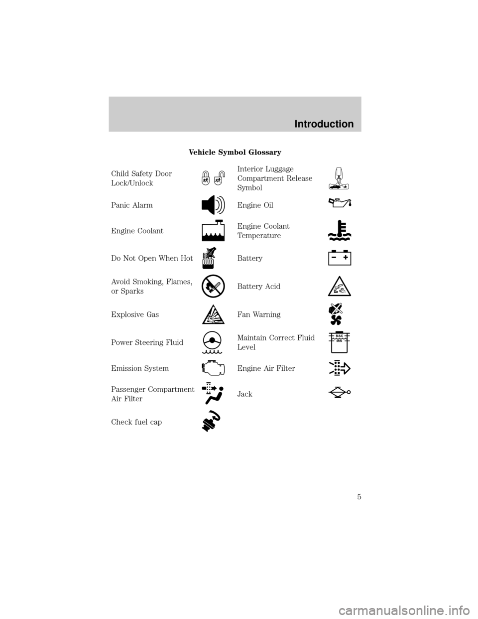
Vehicle Symbol Glossary
Child Safety Door
Lock/Unlock
Interior Luggage
Compartment Release
Symbol
Panic AlarmEngine Oil
Engine CoolantEngine Coolant
Temperature
Do Not Open When HotBattery
Avoid Smoking, Flames,
or SparksBattery Acid
Explosive GasFan Warning
Power Steering FluidMaintain Correct Fluid
LevelMAX
MIN
Emission SystemEngine Air Filter
Passenger Compartment
Air FilterJack
Check fuel cap
Introduction
5
Page 82 of 256

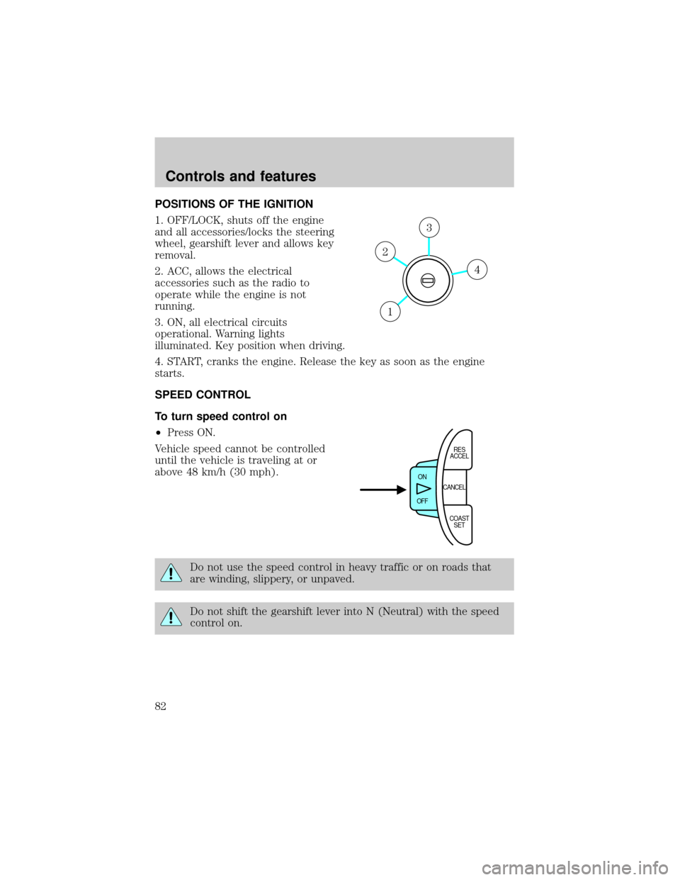
POSITIONS OF THE IGNITION
1. OFF/LOCK, shuts off the engine
and all accessories/locks the steering
wheel, gearshift lever and allows key
removal.
2. ACC, allows the electrical
accessories such as the radio to
operate while the engine is not
running.
3. ON, all electrical circuits
operational. Warning lights
illuminated. Key position when driving.
4. START, cranks the engine. Release the key as soon as the engine
starts.
SPEED CONTROL
To turn speed control on
²Press ON.
Vehicle speed cannot be controlled
until the vehicle is traveling at or
above 48 km/h (30 mph).
Do not use the speed control in heavy traffic or on roads that
are winding, slippery, or unpaved.
Do not shift the gearshift lever into N (Neutral) with the speed
control on.
4
3
2
1
CANCEL ON
OFFRES
ACCEL
COAST
SET
Controls and features
82
Page 86 of 256

To return to a previously set speed
²Press RES/ACCEL. For
RES/ACCEL to operate, the
vehicle speed must be faster than
48 km/h (30 mph).
Indicator light
²Standard analog instrument
cluster
The ªCRUISEº light comes on when
the ON control is pressed.
The ªSETº light comes on when either the COAST/SET or RES/ACCEL
controls are pressed. The ªSETº light turns off when the cruise cancel
control is pressed or the brake is applied. Both the ªCRUISEº and ªSETº
lights turn off when the OFF control is pressed or the ignition is turned
to the OFF position.
²Optional electronic instrument
cluster
This light comes on when either the
COAST/SET or RES/ACCEL controls are pressed. It turns off when the
cruise cancel control is pressed, the brake is applied or the ignition is
turned to the OFF position.
STEERING WHEEL CONTROLS (IF EQUIPPED)
These controls allow you to operate some audio control features.
CANCEL ON
OFFRES
ACCEL
COAST
SET
CRUISE SET
CRUISE
Controls and features
86
Page 90 of 256

For additional information about the gearshift lever and the transmission
control switch operation refer to theAutomatic Transaxle Operation
section of theDrivingchapter.
TILT STEERING WHEEL
Push the tilt steering wheel lever
downward to move the steering
wheel up or down. Push the control
upward to lock the steering wheel in
position.
Never adjust the steering wheel when the vehicle is moving.
POWER WINDOWS
²Press and hold the switch to
open.
²Pull up and hold the switch to
close.
AUTO
L VENT R
Controls and features
90
Page 149 of 256

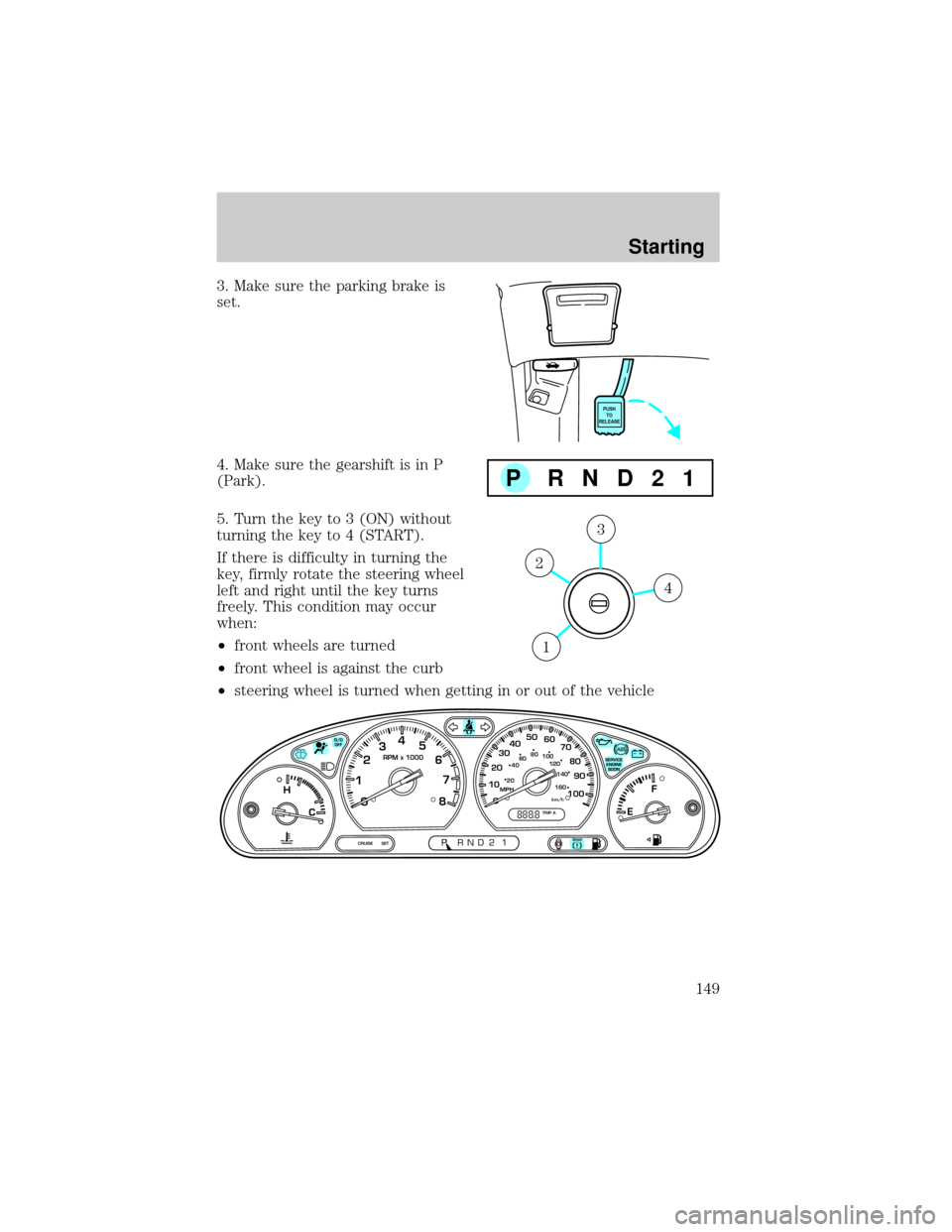
3. Make sure the parking brake is
set.
4. Make sure the gearshift is in P
(Park).
5. Turn the key to 3 (ON) without
turning the key to 4 (START).
If there is difficulty in turning the
key, firmly rotate the steering wheel
left and right until the key turns
freely. This condition may occur
when:
²front wheels are turned
²front wheel is against the curb
²steering wheel is turned when getting in or out of the vehicle
PUSH
TO
RELEASE
P RND21
4
3
2
1
km/h0 1020304050
60
70
80
90
100MPH
TRIP A
RPM x 1000
20406080
100
120
140
160
0 1234
5
6
7
8F
H
CE
CRUISE SETPRND2P1
Starting
149
Page 152 of 256

BRAKES
Your service brakes are self-adjusting. Refer to the scheduled
maintenance guide for scheduled maintenance.
Occasional brake noise is normal and often does not indicate a
performance concern with the vehicle's brake system. In normal
operation, automotive brake systems may emit occasional or intermittent
squeal or groan noises when the brakes are applied. Such noises are
usually heard during the first few brake applications in the morning;
however, they may be heard at any time while braking and can be
aggravated by environmental conditions such as cold, heat, moisture,
road dust, salt or mud. If a ªmetal-to-metal,º ªcontinuous grindingº or
ªcontinuous squealº sound is present while braking, the brake linings
may be worn-out and should be inspected by a qualified service
technician.
Anti-lock brake system (ABS) (if equipped)
On vehicles equipped with an anti-lock braking system (ABS), a noise
from the hydraulic pump motor and pulsation in the pedal may be
observed during ABS braking events. Pedal pulsation coupled with noise
while braking under panic conditions or on loose gravel, bumps, wet or
snowy roads is normal and indicates proper functioning of the vehicle's
anti-lock brake system. The ABS performs a self-check after you start
the engine and begin to drive away. A brief mechanical noise may be
heard during this test. This is normal. If a malfunction is found, the ABS
warning light will come on. If the vehicle has continuous vibration or
shudder in the steering wheel while braking, the vehicle should be
inspected by a qualified service technician.
The ABS operates by detecting the
onset of wheel lockup during brake
applications and compensates for
this tendency. The wheels are
prevented from locking even when
the brakes are firmly applied. The
accompanying illustration depicts
the advantage of an ABS equipped
vehicle (on bottom) to a non-ABS
equipped vehicle (on top) during hard braking with loss of front braking
traction.
Driving
152
Page 153 of 256

ABS warning lampABS
TheABSwarning lamp in the instrument cluster momentarily illuminates
when the ignition is turned to the ON position. If the light does not
illuminate momentarily at start up, remains on or continues to flash, the
ABS needs to be serviced.
With the ABS light on, the anti-lock
brake system is disabled and normal
braking is still effective unless the
brake warning light also remains
illuminated with parking brake
released. (If your brake warning lamp illuminates, have your vehicle
serviced immediately.)
Using ABS
²In an emergency or when maximum efficiency from the four wheel
ABS is required, apply continuous force on the brake. The four wheel
ABS will be activated immediately, thus allowing you to retain full
steering control of your vehicle and, providing there is sufficient
space, will enable you to avoid obstacles and bring the vehicle to a
controlled stop.
²The Anti-Lock system does not decrease the time necessary to apply
the brakes or always reduce stopping distance. Always leave enough
room between your vehicle and the vehicle in front of you to stop.
²We recommend that you familiarize yourself with this braking
technique. However, avoid taking any unnecessary risks.
Parking brake
Apply the parking brake whenever
the vehicle is parked. To set the
parking brake, press the parking
brake pedal down until the pedal
stops.
P!
BRAKE
PUSH
TO
RELEASE
Driving
153
Page 154 of 256

The BRAKE warning lamp in the
instrument cluster illuminates and
remains illuminated (when the
ignition is turned ON) until the
parking brake is released.
Always set the parking brake fully and make sure that the
gearshift is securely latched in P (Park).
The parking brake is not recommended to stop a moving vehicle.
However, if the normal brakes fail, the parking brake can be used to stop
your vehicle in an emergency. Since the parking brake applies only the
rear brakes, the vehicle's stopping distance will increase greatly and the
handling of your vehicle will be adversely affected.
Push the pedal downward again to
release the parking brake. Driving
with the parking brake on will cause
the brakes to wear out quickly and
reduce fuel economy.
STEERING
Your vehicle is equipped with power steering. Power steering uses energy
from the engine to help steer the vehicle.
To prevent damage to the power steering pump:
²Never hold the steering wheel to the extreme right or the extreme left
for more than a few seconds when the engine is running.
²Do not operate the vehicle with a low power steering pump fluid level
(below the MIN mark on the reservoir).
If the power steering system breaks down (or if the engine is turned
off), you can steer the vehicle manually, but it takes more effort.
If the steering wanders or pulls, the condition could be caused by any of
the following:
²underinflated tire(s) on any wheel(s)
P!
BRAKE
PUSH
TO
RELEASE
Driving
154
Page 169 of 256

Standard fuse amperage rating and color
COLOR
Fuse
RatingMini
FusesStandard
FusesMaxi
FusesCartridge
Maxi
FusesFuse Link
Cartridge
2A Grey Grey Ð Ð Ð
3A Violet Violet Ð Ð Ð
4A Pink Pink Ð Ð Ð
5A Tan Tan Ð Ð Ð
7.5A Brown Brown Ð Ð Ð
10A Red Red Ð Ð Ð
15A Blue Blue Ð Ð Ð
20A Yellow Yellow Yellow Blue Blue
25A Natural Natural Ð Ð Ð
30A Green Green Green Pink Pink
40A Ð Ð Orange Green Green
50A Ð Ð Red Red Red
60A Ð Ð Blue Ð Yellow
70A Ð Ð Tan Ð Brown
80A Ð Ð Natural Ð Black
For fuses greater than 80A, please see your Ford or Lincoln Mercury
Dealer.
Passenger compartment fuse panel
The fuse panel is located below and to the left of the steering wheel by
the brake pedal. Remove the panel cover to access the fuses.
To remove a fuse use the fuse puller tool provided on the fuse panel
cover.
Roadside emergencies
169
Page 175 of 256

CHANGING THE TIRES
If you get a flat tire while driving, do not apply the brake heavily.
Instead, gradually decrease your speed. Hold the steering wheel firmly
and slowly move to a safe place on the side of the road.
Temporary spare tire information
Your vehicle may have a temporary or conventional size spare tire. The
temporary spare tire for your vehicle is labeled as such. It is smaller than
a regular tire and is designed for emergency use only. Replace this tire
with a full-size tire as soon as possible.
If you use the temporary spare tire continuously or do not follow
these precautions, the tire could fail, causing you to lose control
of the vehicle, possibly injuring yourself or others.
When driving with the temporary spare tiredo not:
²exceed 80 km/h (50 mph) under any circumstances
²load the vehicle beyond maximum vehicle load rating listed on the
Certification Label
²tow a trailer
²use tire chains
²drive through an automatic car wash, because of the vehicle's reduced
ground clearance
²try to repair the temporary spare tire or remove it from its wheel
²use the wheel for any other type of vehicle
Location of the spare tire and tools
The spare tire and tools for your vehicle are stowed in the following
locations:
Item Location
Spare tire Under the vehicle, just forward of the rear bumper
Jack assembly Under the third row bench seat in the tool bag
Removing the jack and tools
1. Lift the 3rd row seat cushion.
2. Remove the jack assembly from the bag under the seat.
Roadside emergencies
175