navigation MINI 3 door 2015 User Guide
[x] Cancel search | Manufacturer: MINI, Model Year: 2015, Model line: 3 door, Model: MINI 3 door 2015Pages: 248, PDF Size: 5.43 MB
Page 92 of 248

On the Control Display:1. "Settings"2."Head-Up Display"3."Rotation"4.Turn the Controller until the desired setting
is selected.5.Press the Controller.
Settings are stored for the profile currently
used.
John Cooper Works: Sport displays in
the Head-up Display
General information The sport displays in the Head-up Display assist
with a sporty driving style.
Switching on
1. "Settings"2."Head-Up Display"3."Displayed information"4."Sport displays"
With navigation system: if the sport displays are
switched on, no navigation content will be dis‐
played on the Head-up Display.
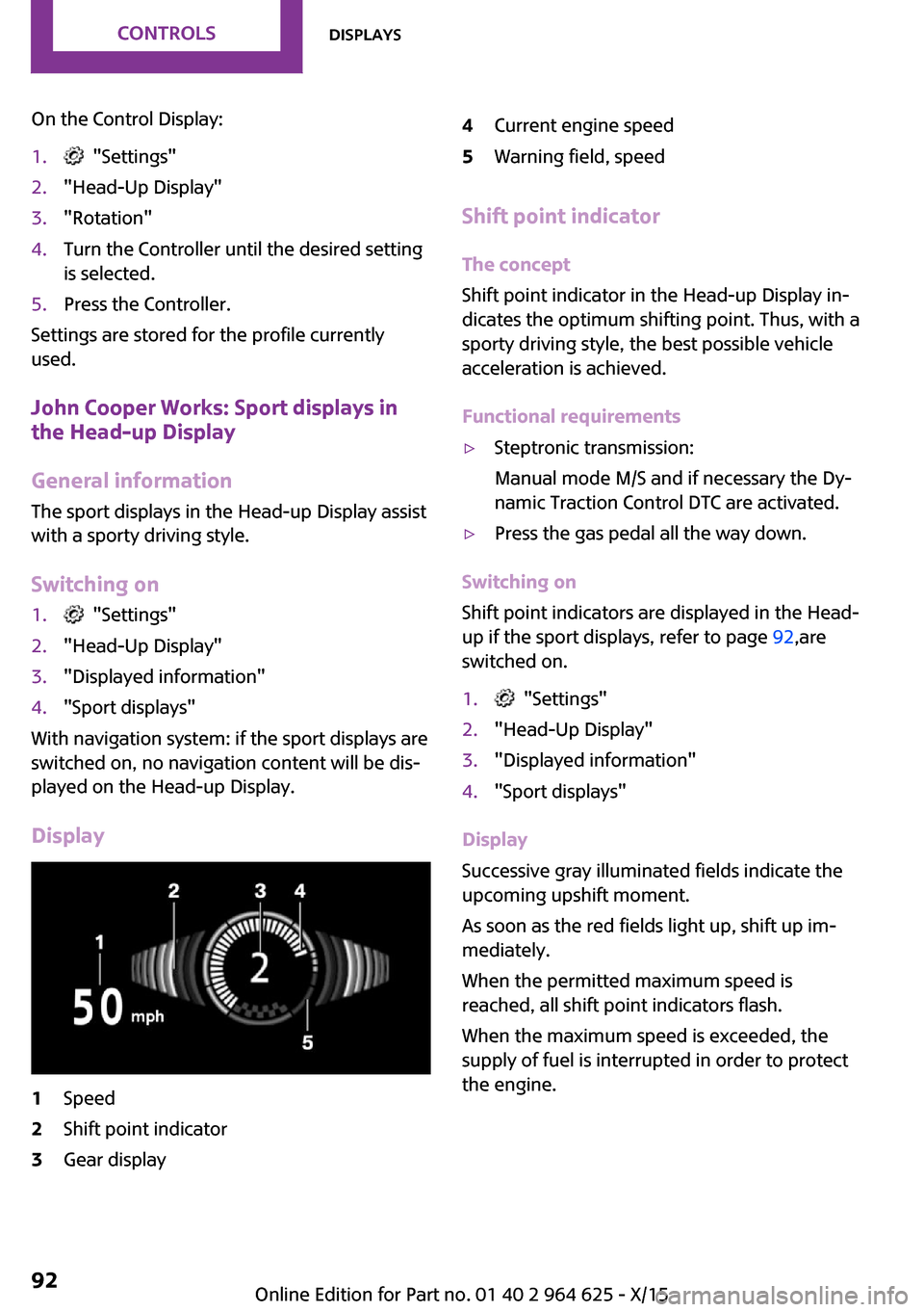
Display
1Speed2Shift point indicator3Gear display4Current engine speed5Warning field, speed
Shift point indicator
The concept
Shift point indicator in the Head-up Display in‐
dicates the optimum shifting point. Thus, with a
sporty driving style, the best possible vehicle
acceleration is achieved.
Functional requirements
▷Steptronic transmission:
Manual mode M/S and if necessary the Dy‐
namic Traction Control DTC are activated.▷Press the gas pedal all the way down.
Switching on
Shift point indicators are displayed in the Head-
up if the sport displays, refer to page 92,are
switched on.
1. "Settings"2."Head-Up Display"3."Displayed information"4."Sport displays"
Display
Successive gray illuminated fields indicate the
upcoming upshift moment.
As soon as the red fields light up, shift up im‐
mediately.
When the permitted maximum speed is
reached, all shift point indicators flash.
When the maximum speed is exceeded, the
supply of fuel is interrupted in order to protect
the engine.
Seite 92CONTROLSDisplays92
Online Edition for Part no. 01 40 2 964 625 - X/15
Page 149 of 248

Settings are stored automatically after approxi‐
mately 10 seconds.
Sun visor
Glare shield
Fold the sun visor down or up.
Vanity mirror
A vanity mirror is located in the sun visor be‐
hind a cover.
When the cover is opened, the mirror lighting
switches on.
Ashtray/cigarette
lighter
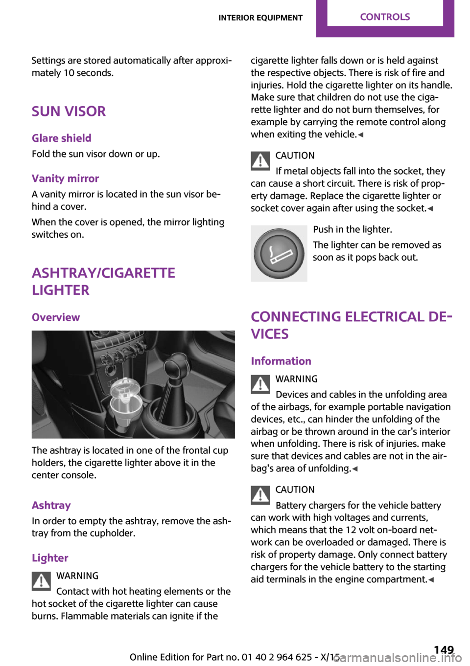
Overview
The ashtray is located in one of the frontal cup
holders, the cigarette lighter above it in the
center console.
Ashtray In order to empty the ashtray, remove the ash‐
tray from the cupholder.
Lighter WARNING
Contact with hot heating elements or the
hot socket of the cigarette lighter can cause
burns. Flammable materials can ignite if the
cigarette lighter falls down or is held against
the respective objects. There is risk of fire and
injuries. Hold the cigarette lighter on its handle.
Make sure that children do not use the ciga‐
rette lighter and do not burn themselves, for
example by carrying the remote control along
when exiting the vehicle. ◀
CAUTION
If metal objects fall into the socket, they
can cause a short circuit. There is risk of prop‐
erty damage. Replace the cigarette lighter or
socket cover again after using the socket. ◀
Push in the lighter.
The lighter can be removed as
soon as it pops back out.
Connecting electrical de‐
vices
Information WARNING
Devices and cables in the unfolding area
of the airbags, for example portable navigation
devices, etc., can hinder the unfolding of the
airbag or be thrown around in the car's interior
when unfolding. There is risk of injuries. make
sure that devices and cables are not in the air‐
bag's area of unfolding. ◀
CAUTION
Battery chargers for the vehicle battery
can work with high voltages and currents,
which means that the 12 volt on-board net‐
work can be overloaded or damaged. There is
risk of property damage. Only connect battery
chargers for the vehicle battery to the starting
aid terminals in the engine compartment. ◀Seite 149Interior equipmentCONTROLS149
Online Edition for Part no. 01 40 2 964 625 - X/15
Page 215 of 248

InformationCAUTION
Battery chargers for the vehicle battery
can work with high voltages and currents, which means that the 12 volt on-board net‐
work can be overloaded or damaged. There is risk of property damage. Only connect battery
chargers for the vehicle battery to the starting
aid terminals in the engine compartment. ◀
Starting aid terminals
In the vehicle, only charge the battery via the
starting aid terminals, refer to page 217, in the
engine compartment with the engine off.
Power failure
After a power loss, some equipment needs to
be newly initialized or individual settings up‐
dated, for example:▷Time: update.▷Date: update.▷Navigation system: wait for the operability
of the navigation.▷Seat and mirror memory: store the posi‐
tions again.▷Glass sunroof: initialize the system, refer to
page 48.
Disposing of old batteries
Have old batteries disposed of by a
dealer’s service center or another quali‐
fied service center or repair shop or
take them to a collection point.
Maintain the battery in an upright position for
transport and storage. Secure the battery so
that it does not tip over during transport.
Fuses
Information WARNING
Incorrect and repaired fuses can overload
electrical lines and components. There is risk of
fire. Never attempt to repair a blown fuse. Do
not replace a nonworking fuse with a substitute
of another color or amperage rating. ◀
Plastic tweezers and information on the fuse
types and locations are stored in the fuse box in
the glove compartment.
Replacing fuse
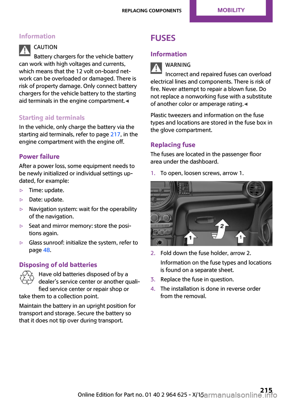
The fuses are located in the passenger floor
area under the dashboard.1.To open, loosen screws, arrow 1.2.Fold down the fuse holder, arrow 2.
Information on the fuse types and locations
is found on a separate sheet.3.Replace the fuse in question.4.The installation is done in reverse order
from the removal.Seite 215Replacing componentsMOBILITY215
Online Edition for Part no. 01 40 2 964 625 - X/15
Page 243 of 248

Minimum tread, tires 187
Mirrors 55
Mobile communication devi‐ ces in the vehicle 161
Mobility System 190
Mode, GREEN Mode 167
Modifications, technical, refer to Own Safety 7
Moisture in headlight 205
Monitor, refer to Control Dis‐ play 18
Mounting of child restraint systems 59
Multifunction steering wheel, buttons 14
Multimedia, refer to Integrated Owner's Manual
N Navigation, refer to Integrated Owner's Manual
Neck restraints, front, see Head restraints 53
Neck restraints, rear, see Head restraints 54
New wheels and tires 188
O OBD Onboard Diagnos‐ tics 203
Obstacle marking, rearview camera 132
Octane rating, see Recom‐ mended fuel grade 178
Odometer 81
Office, refer to Integrated Owner's Manual
Oil 196
Oil, adding 197
Oil additives 198
Oil change 198
Oil change interval, service re‐ quirements 82
Oil filler neck 197 Oil types, alternative 198
Oil types, suitable 198
Old batteries, disposal 215
On-board computer 85
On-board computer, refer to On-board computer 85
Onboard Diagnostics OBD 203
Onboard monitor 18
Onboard monitor operating concept 18
Onboard vehicle tool kit 204
Opening/closing via door lock 39
Opening/closing with remote control 37
Operating menus, onboard monitor 18
Optional equipment, standard equipment 7
Outside air, see Automatic re‐ circulated-air control 142
Own safety 7
P
Paint, vehicle 222
Panoramic glass sunroof 47
Parallel parking assistant 133
Park Distance Control PDC 128
Parked-car ventilation 143
Parked vehicle, condensa‐ tion 162
Parking aid, see PDC 128
Parking assistant 133
Parking brake 66
Parking lights 95
Parts and accessories 8
Passenger side mirror, tilting downward 55
Pathway lines, rearview cam‐ era 132
PDC Park Distance Con‐ trol 128
Performance Control 117 Personal Profile 36
Person warning with City light braking function 113
Phone, refer to Integrated Owner's Manual
Pinch protection system, glass sunroof 48
Pinch protection system, win‐ dows 46
Plastic, care 223
PostCrash 115
Power failure 215
Power windows 45
Prescribed engine oil types 198
Pressure, tire air pressure 180
Pressure warning, tires 107
Profile, see Personal Pro‐ file 36
Protective function, glass sun‐ roof 48
Protective function, win‐ dows 46
Push-and-turn switch, see Controller 19
R
Radiator fluid 200
Radio-operated key, see Re‐ mote control 34
Radio ready state 62
Radio, refer to Integrated Owner's Manual
Rain sensor 69
Rear fog lights 98
Rear lights 208
Rear luggage rack 165
Rearview camera 131
Rearview mirror 55
Rear window de‐ froster 140, 143
Recirculated-air filter 143
Recirculated-air mode 139, 142 Seite 243Everything from A to ZREFERENCE243
Online Edition for Part no. 01 40 2 964 625 - X/15