tow MINI 3 door 2015 Owner's Guide
[x] Cancel search | Manufacturer: MINI, Model Year: 2015, Model line: 3 door, Model: MINI 3 door 2015Pages: 248, PDF Size: 5.43 MB
Page 162 of 248
Objects in the area around the pedalsWARNING
Objects in the driver's floor area can limit
the pedal distance or block a depressed pedal.
There is risk of an accident. Stow objects in the
vehicle such that they are secured and cannot
enter into the driver's floor area. Use floor mats
that are suitable for the vehicle and can be
safely attached to the floor. Do not use loose
floor mats and do not layer several floor mats.
Make sure that there is sufficient clearance for
the pedals. Ensure that the floor mats are se‐
curely fastened again after they were removed,
for example for cleaning. ◀
Driving in wet conditions When roads are wet, salted, or in heavy rain,
press brake pedal ever so gently every few
miles.
Ensure that this action does not endanger other
traffic.
The heat generated in this process helps dry
the brake discs and pads.
In this way braking efficiency will be available
when you need it.
Hills WARNING
Light but consistent brake pressure can
lead to high temperatures, brakes wearing out
and possibly even brake failure. There is risk of
an accident. Avoid placing excessive stress on
the brake system. ◀
WARNING
In idle or with the engine switched off,
safety-relevant functions are restricted or not
available anymore, for example braking effect
of the engine or braking force and steering
support. There is risk of an accident. Do not
drive in idle or with the engine switched off. ◀
Drive long or steep downhill gradients in the
gear that requires least braking efforts. Other‐wise the brakes may overheat and reduce
brake efficiency.
You can increase the engine's braking effect by
shifting down, going all the way to first gear, if
needed.
Brake disc corrosion Corrosion on the brake discs and contamina‐
tion on the brake pads are furthered by:▷Low mileage.▷Extended periods when the vehicle is not
used at all.▷Infrequent use of the brakes.
Corrosion will built up when the maximum
pressure applied to the brake pads during brak‐
ing is not reached - thus discs don't get
cleaned.
Corrosion buildup on the brake discs will cause
a pulsating effect on the brakes in their re‐
sponse - generally that cannot be corrected.
Condensation under the parked vehicle When using the automatic climate control, con‐
densation water develops collecting under‐
neath the vehicle.
Ground clearance CAUTION
If ground clearance is insufficient, there
might be contact with the front or rear spoiler
for example when driving over curbs or enter‐
ing into underground car parking garages.
There is risk of property damage. Ensure that
there is sufficient ground clearance available. ◀
Seite 162DRIVING TIPSThings to remember when driving162
Online Edition for Part no. 01 40 2 964 625 - X/15
Page 164 of 248
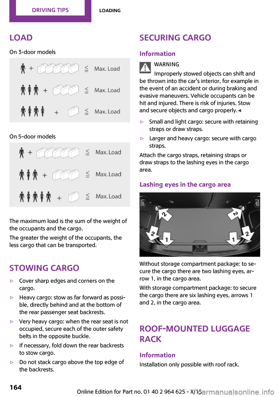
LoadOn 3-door modelsOn 5-door models
The maximum load is the sum of the weight of
the occupants and the cargo.
The greater the weight of the occupants, the
less cargo that can be transported.
Stowing cargo
▷Cover sharp edges and corners on the
cargo.▷Heavy cargo: stow as far forward as possi‐
ble, directly behind and at the bottom of
the rear passenger seat backrests.▷Very heavy cargo: when the rear seat is not
occupied, secure each of the outer safety
belts in the opposite buckle.▷If necessary, fold down the rear backrests
to stow cargo.▷Do not stack cargo above the top edge of
the backrests.Securing cargo
Information WARNING
Improperly stowed objects can shift and
be thrown into the car's interior, for example in
the event of an accident or during braking and
evasive maneuvers. Vehicle occupants can be
hit and injured. There is risk of injuries. Stow
and secure objects and cargo properly. ◀▷Small and light cargo: secure with retaining
straps or draw straps.▷Larger and heavy cargo: secure with cargo
straps.
Attach the cargo straps, retaining straps or
draw straps to the lashing eyes in the cargo
area.
Lashing eyes in the cargo area
Without storage compartment package: to se‐
cure the cargo there are two lashing eyes, ar‐
row 1, in the cargo area.
With storage compartment package: to secure
the cargo there are six lashing eyes, arrows 1
and 2, in the cargo area.
Roof-mounted luggage
rack
Information Installation only possible with roof rack.
Seite 164DRIVING TIPSLoading164
Online Edition for Part no. 01 40 2 964 625 - X/15
Page 171 of 248
Display
Display in the instrument cluster The mark in the bar display be‐
low the tachometer is high‐
lighted green and appears at the
zero point. The tachometer ap‐
proximately indicates idle speed.
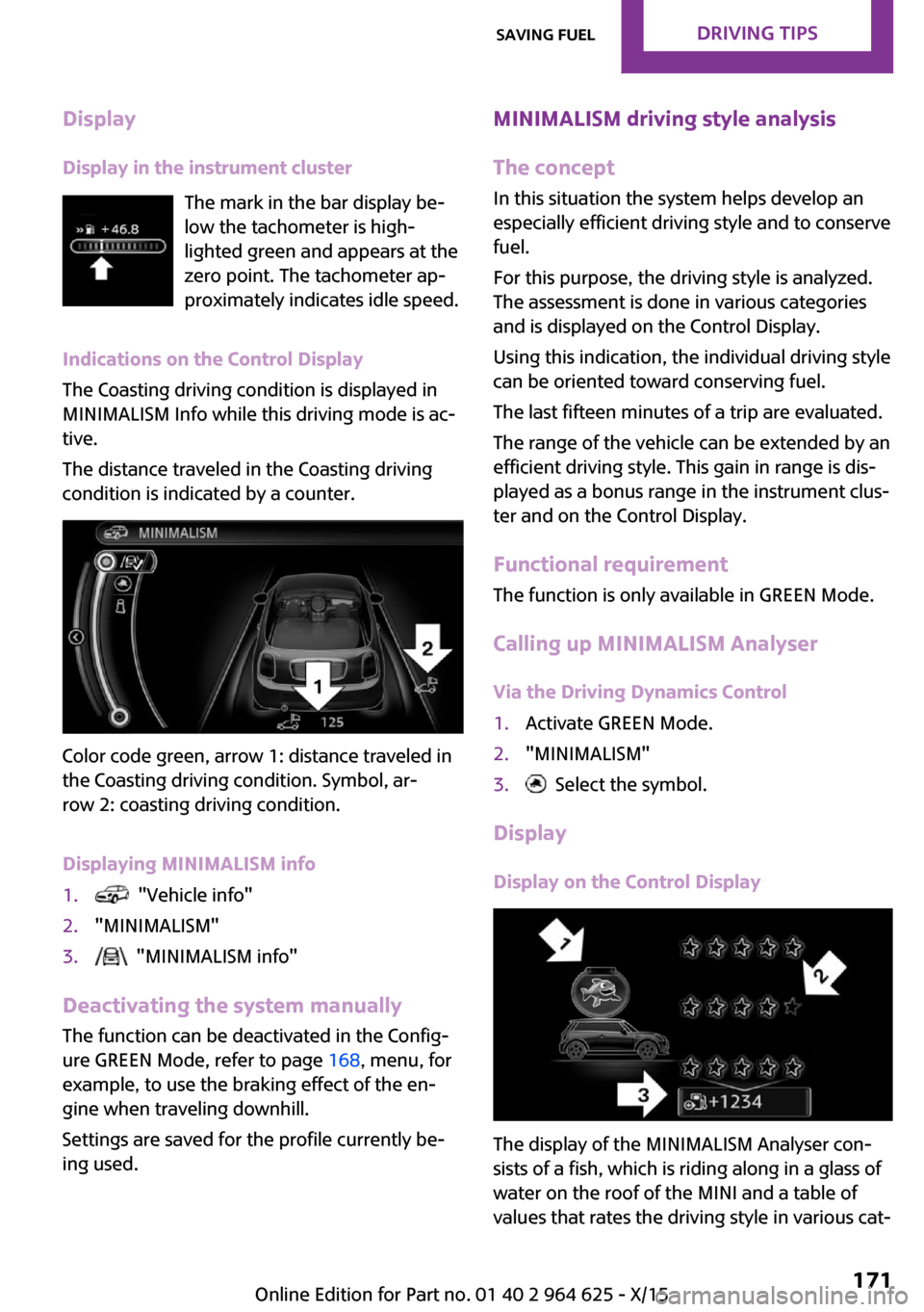
Indications on the Control Display
The Coasting driving condition is displayed in
MINIMALISM Info while this driving mode is ac‐
tive.
The distance traveled in the Coasting driving
condition is indicated by a counter.
Color code green, arrow 1: distance traveled in
the Coasting driving condition. Symbol, ar‐
row 2: coasting driving condition.
Displaying MINIMALISM info
1. "Vehicle info"2."MINIMALISM"3. "MINIMALISM info"
Deactivating the system manually The function can be deactivated in the Config‐
ure GREEN Mode, refer to page 168, menu, for
example, to use the braking effect of the en‐
gine when traveling downhill.
Settings are saved for the profile currently be‐
ing used.
MINIMALISM driving style analysis
The concept
In this situation the system helps develop an
especially efficient driving style and to conserve
fuel.
For this purpose, the driving style is analyzed.
The assessment is done in various categories
and is displayed on the Control Display.
Using this indication, the individual driving style
can be oriented toward conserving fuel.
The last fifteen minutes of a trip are evaluated.
The range of the vehicle can be extended by an
efficient driving style. This gain in range is dis‐
played as a bonus range in the instrument clus‐
ter and on the Control Display.
Functional requirement
The function is only available in GREEN Mode.
Calling up MINIMALISM Analyser Via the Driving Dynamics Control1.Activate GREEN Mode.2."MINIMALISM"3. Select the symbol.
Display
Display on the Control Display
The display of the MINIMALISM Analyser con‐
sists of a fish, which is riding along in a glass of
water on the roof of the MINI and a table of
values that rates the driving style in various cat‐
Seite 171Saving fuelDRIVING TIPS171
Online Edition for Part no. 01 40 2 964 625 - X/15
Page 188 of 248
They are marked on the side of the tire with
TWI, Tread Wear Indicator.
Tire damage General information
Inspect your tires regularly for damage, foreign
objects lodged in the tread, and tread wear.
Information Driving over rough or damaged road surfaces,
as well as debris, curbs and other obstacles can
cause serious damage to wheels, tires and sus‐
pension parts. This is more likely to occur with
low-profile tires, which provide less cushioning
between the wheel and the road. Be careful to
avoid road hazards and reduce your speed, es‐
pecially if your vehicle is equipped with low-
profile tires.
Indications of tire damage or other vehicle mal‐
functions:▷Unusual vibrations while driving.▷Unusual handling such as a strong ten‐
dency to pull to the left or right.
Damage can, e. g., be caused by driving over
curbs, road damage, or similar things.
WARNING
Damaged tires can lose tire inflation pres‐
sure, which can lead to loss of vehicle control.
There is risk of an accident. If tire damage is
suspected while driving, immediately reduce
speed and stop. Have wheels and tires
checked. For this purpose, drive carefully to the
nearest dealer’s service center or another
qualified service center or repair shop. Have
vehicle towed or transported as needed. ◀
WARNING
Damaged tires can lose tire inflation pres‐
sure, which can lead to loss of vehicle control.
There is risk of an accident. Do not repair dam‐
aged tires, but have them replaced. ◀
Changing wheels and
tires
Mounting Have mounting and wheel balancing carried
out by a dealer’s service center or another
qualified service center or repair shop.
Wheel and tire combination
You can ask the dealer’s service center or an‐
other qualified service center or repair shop
about the right wheel/tire combination and
wheel rim versions for the vehicle.
Incorrect wheel and tire combinations impair
the function of a variety of systems such as ABS
or DSC.
To maintain good handling and vehicle re‐
sponse, use only tires with a single tread con‐
figuration from a single manufacturer.
Following tire damage, have the original wheel
and tire combination remounted on the vehicle
as soon as possible.
WARNING
Wheels and tires which are not suitable
for your vehicle can damage parts of the vehi‐
cle, e.g. due to contact with the body due to
tolerances despite the same official size rating.
There is risk of an accident. The manufacturer
of your vehicle strongly suggests that you use
wheels and tires that have been recommended
by the vehicle manufacturer for your vehicle
type. ◀Seite 188MOBILITYWheels and tires188
Online Edition for Part no. 01 40 2 964 625 - X/15
Page 192 of 248
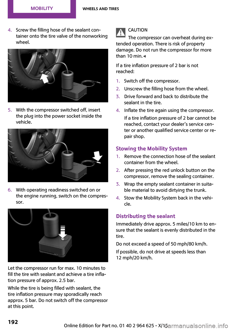
4.Screw the filling hose of the sealant con‐
tainer onto the tire valve of the nonworking
wheel.5.With the compressor switched off, insert
the plug into the power socket inside the
vehicle.6.With operating readiness switched on or
the engine running, switch on the compres‐
sor.
Let the compressor run for max. 10 minutes to
fill the tire with sealant and achieve a tire infla‐
tion pressure of approx. 2.5 bar.
While the tire is being filled with sealant, the
tire inflation pressure may sporadically reach
approx. 5 bar. Do not switch off the compressor
at this point.
CAUTION
The compressor can overheat during ex‐
tended operation. There is risk of property
damage. Do not run the compressor for more
than 10 min. ◀
If a tire inflation pressure of 2 bar is not
reached:1.Switch off the compressor.2.Unscrew the filling hose from the wheel.3.Drive forward and back to distribute the
sealant in the tire.4.Inflate the tire again using the compressor.
If a tire inflation pressure of 2 bar cannot be
reached, contact your dealer’s service cen‐
ter or another qualified service center or re‐
pair shop.
Stowing the Mobility System
1.Remove the connection hose of the sealant
container from the wheel.2.After pressing the red unlock button on the
compressor, remove the sealing container.3.Wrap the empty sealant container in suita‐
ble material to avoid dirtying the trunk.4.Stow the Mobility System back in the vehi‐
cle.
Distributing the sealant
Immediately drive approx. 5 miles/10 km to en‐
sure that the sealant is evenly distributed in the
tire.
Do not exceed a speed of 50 mph/80 km/h.
If possible, do not drive at speeds less than
12 mph/20 km/h.
Seite 192MOBILITYWheels and tires192
Online Edition for Part no. 01 40 2 964 625 - X/15
Page 213 of 248
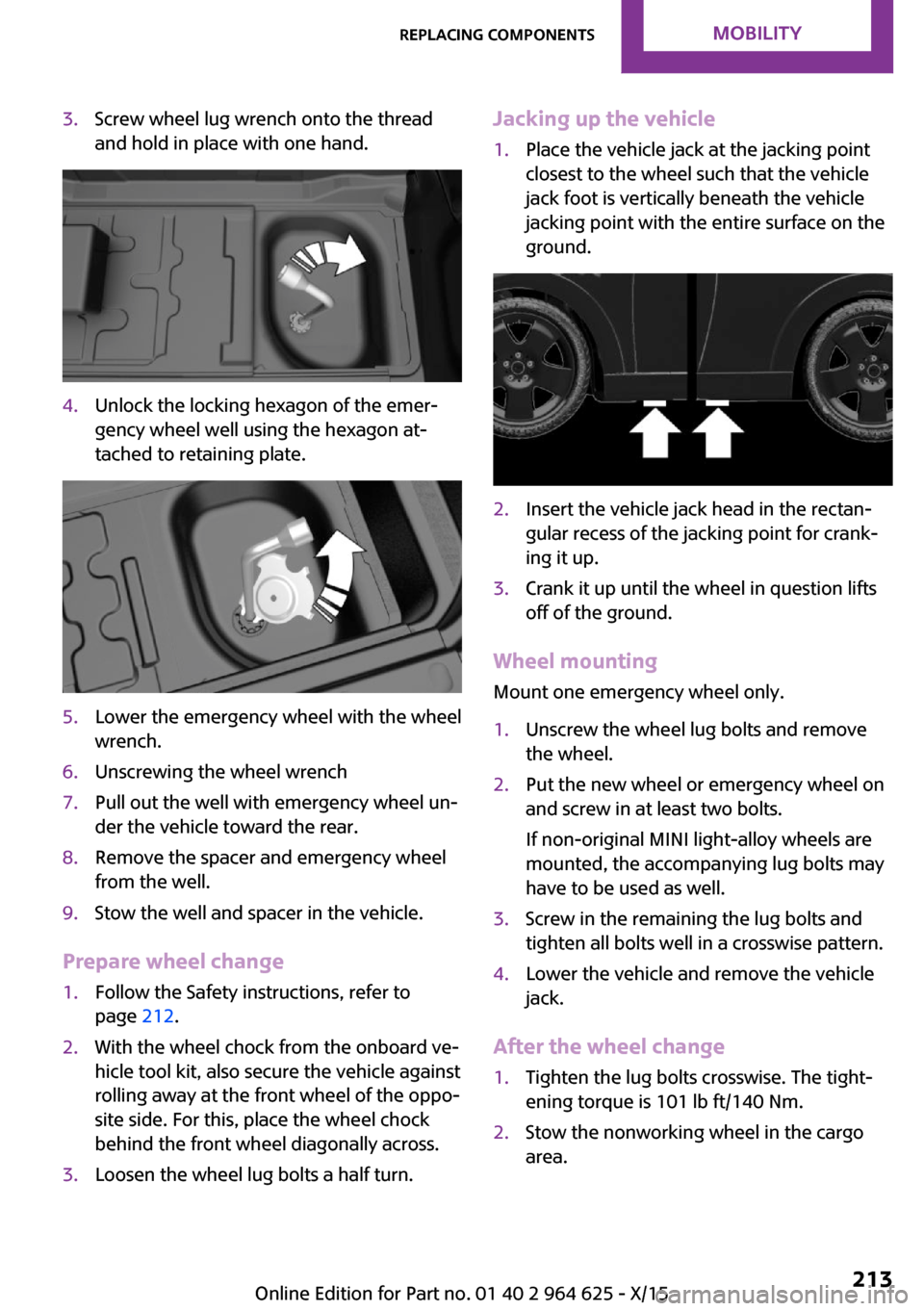
3.Screw wheel lug wrench onto the thread
and hold in place with one hand.4.Unlock the locking hexagon of the emer‐
gency wheel well using the hexagon at‐
tached to retaining plate.5.Lower the emergency wheel with the wheel
wrench.6.Unscrewing the wheel wrench7.Pull out the well with emergency wheel un‐
der the vehicle toward the rear.8.Remove the spacer and emergency wheel
from the well.9.Stow the well and spacer in the vehicle.
Prepare wheel change
1.Follow the Safety instructions, refer to
page 212.2.With the wheel chock from the onboard ve‐
hicle tool kit, also secure the vehicle against
rolling away at the front wheel of the oppo‐
site side. For this, place the wheel chock
behind the front wheel diagonally across.3.Loosen the wheel lug bolts a half turn.Jacking up the vehicle1.Place the vehicle jack at the jacking point
closest to the wheel such that the vehicle
jack foot is vertically beneath the vehicle
jacking point with the entire surface on the
ground.2.Insert the vehicle jack head in the rectan‐
gular recess of the jacking point for crank‐
ing it up.3.Crank it up until the wheel in question lifts
off of the ground.
Wheel mounting
Mount one emergency wheel only.
1.Unscrew the wheel lug bolts and remove
the wheel.2.Put the new wheel or emergency wheel on
and screw in at least two bolts.
If non-original MINI light-alloy wheels are
mounted, the accompanying lug bolts may
have to be used as well.3.Screw in the remaining the lug bolts and
tighten all bolts well in a crosswise pattern.4.Lower the vehicle and remove the vehicle
jack.
After the wheel change
1.Tighten the lug bolts crosswise. The tight‐
ening torque is 101 lb ft/140 Nm.2.Stow the nonworking wheel in the cargo
area.Seite 213Replacing componentsMOBILITY213
Online Edition for Part no. 01 40 2 964 625 - X/15
Page 218 of 248
3.Let both engines run for several minutes.4.Disconnect the jumper cables in the reverse
order.
Check the battery and recharge if needed.
Tow-starting and towing
Information WARNING
Due to system limits, individual functions
can malfunction during tow-starting/towing
with the Intelligent Safety systems activated,
for example approach control warning with
light braking function. There is risk of an acci‐
dent. Switch all Intelligent Safety systems off
prior to tow-starting/towing. ◀
Switching off Intelligent Safety systems, refer to
page 109.
Steptronic transmission: transporting
the vehicle
Information The vehicle must not be towed if the front
wheels are touching the ground.
CAUTION
The vehicle can be damaged when tow‐
ing the vehicle with a lifted rear axle. There is
risk of property damage. Have vehicle trans‐
ported only with lifted front axle or on a load‐
ing platform. ◀
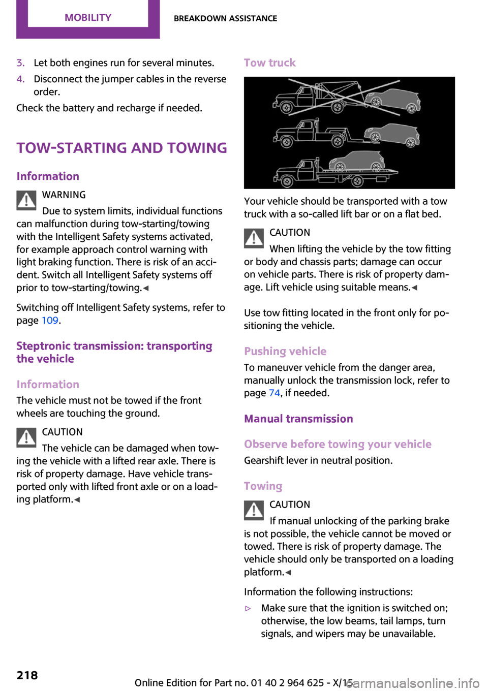
Tow truck
Your vehicle should be transported with a tow
truck with a so-called lift bar or on a flat bed.
CAUTION
When lifting the vehicle by the tow fitting
or body and chassis parts; damage can occur
on vehicle parts. There is risk of property dam‐
age. Lift vehicle using suitable means. ◀
Use tow fitting located in the front only for po‐
sitioning the vehicle.
Pushing vehicle
To maneuver vehicle from the danger area,
manually unlock the transmission lock, refer to
page 74, if needed.
Manual transmission
Observe before towing your vehicle
Gearshift lever in neutral position.
Towing CAUTION
If manual unlocking of the parking brake
is not possible, the vehicle cannot be moved or
towed. There is risk of property damage. The
vehicle should only be transported on a loading
platform. ◀
Information the following instructions:
▷Make sure that the ignition is switched on;
otherwise, the low beams, tail lamps, turn
signals, and wipers may be unavailable.Seite 218MOBILITYBreakdown assistance218
Online Edition for Part no. 01 40 2 964 625 - X/15
Page 219 of 248
▷Do not tow the vehicle with the rear axle
tilted, as the front wheels could turn.▷When the engine is stopped, there is no
power assist. Consequently, more force
needs to be applied when braking and
steering.▷Larger steering wheel movements are re‐
quired.▷The towing vehicle must not be lighter than
the vehicle being towed; otherwise, it will
not be possible to control the vehicle's re‐
sponse.▷Do not exceed a towing speed of
30 mph/50 km/h.▷Do not exceed a towing distance of
30 miles/50 km.
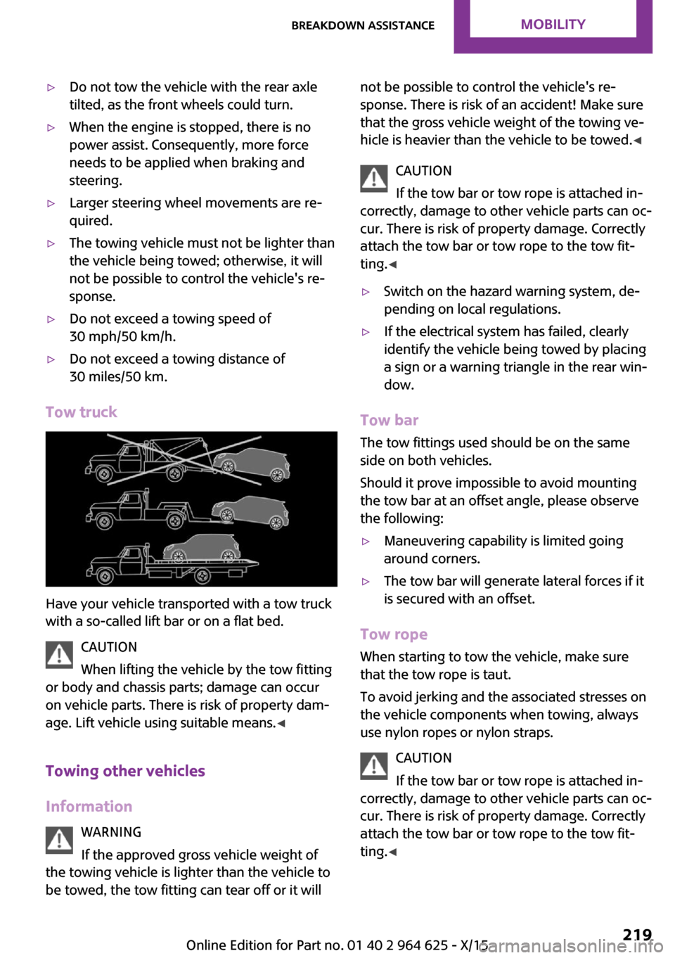
Tow truck
Have your vehicle transported with a tow truck
with a so-called lift bar or on a flat bed.
CAUTION
When lifting the vehicle by the tow fitting
or body and chassis parts; damage can occur
on vehicle parts. There is risk of property dam‐
age. Lift vehicle using suitable means. ◀
Towing other vehicles
Information WARNING
If the approved gross vehicle weight of
the towing vehicle is lighter than the vehicle to
be towed, the tow fitting can tear off or it will
not be possible to control the vehicle's re‐
sponse. There is risk of an accident! Make sure
that the gross vehicle weight of the towing ve‐
hicle is heavier than the vehicle to be towed. ◀
CAUTION
If the tow bar or tow rope is attached in‐
correctly, damage to other vehicle parts can oc‐
cur. There is risk of property damage. Correctly
attach the tow bar or tow rope to the tow fit‐
ting. ◀▷Switch on the hazard warning system, de‐
pending on local regulations.▷If the electrical system has failed, clearly
identify the vehicle being towed by placing
a sign or a warning triangle in the rear win‐
dow.
Tow bar
The tow fittings used should be on the same
side on both vehicles.
Should it prove impossible to avoid mounting
the tow bar at an offset angle, please observe
the following:
▷Maneuvering capability is limited going
around corners.▷The tow bar will generate lateral forces if it
is secured with an offset.
Tow rope
When starting to tow the vehicle, make sure
that the tow rope is taut.
To avoid jerking and the associated stresses on
the vehicle components when towing, always
use nylon ropes or nylon straps.
CAUTION
If the tow bar or tow rope is attached in‐
correctly, damage to other vehicle parts can oc‐ cur. There is risk of property damage. Correctly
attach the tow bar or tow rope to the tow fit‐ ting. ◀
Seite 219Breakdown assistanceMOBILITY219
Online Edition for Part no. 01 40 2 964 625 - X/15
Page 220 of 248
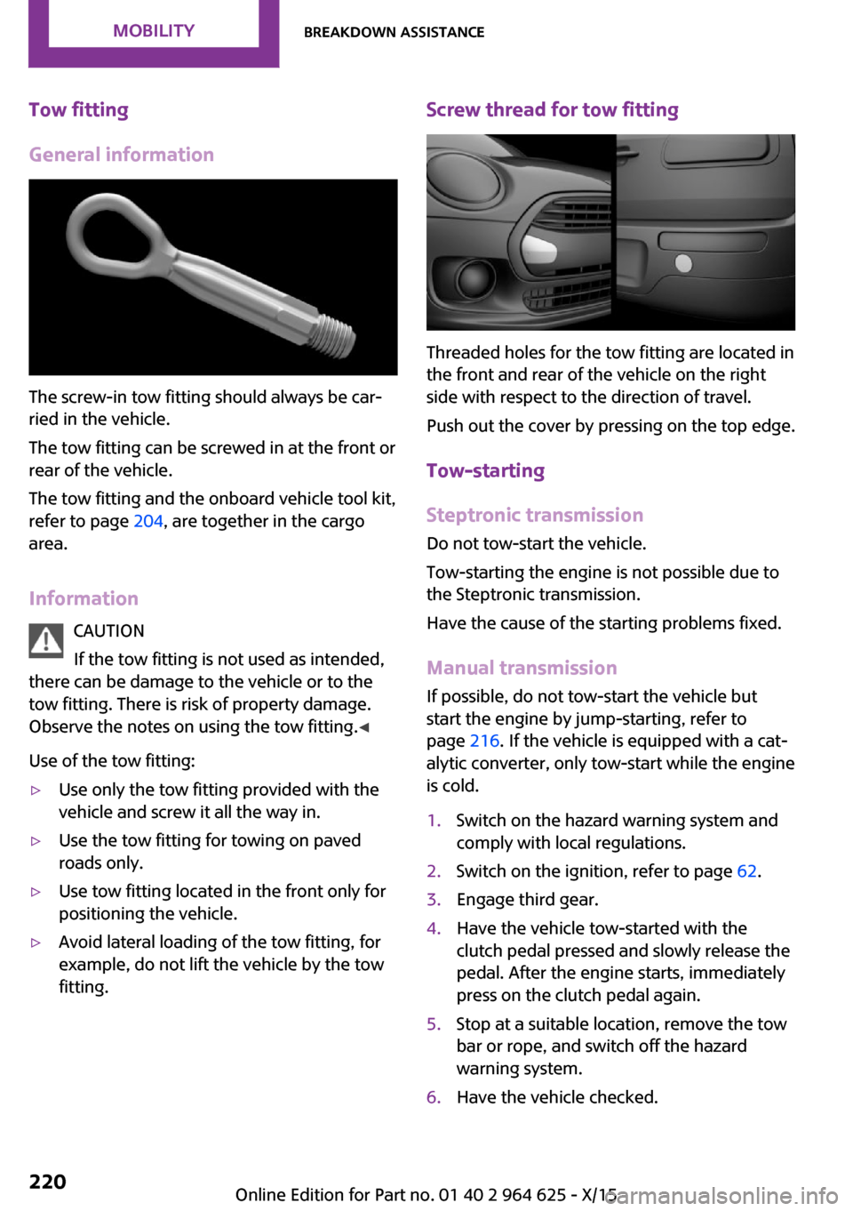
Tow fitting
General information
The screw-in tow fitting should always be car‐
ried in the vehicle.
The tow fitting can be screwed in at the front or
rear of the vehicle.
The tow fitting and the onboard vehicle tool kit,
refer to page 204, are together in the cargo
area.
Information CAUTION
If the tow fitting is not used as intended,
there can be damage to the vehicle or to the
tow fitting. There is risk of property damage.
Observe the notes on using the tow fitting. ◀
Use of the tow fitting:
▷Use only the tow fitting provided with the
vehicle and screw it all the way in.▷Use the tow fitting for towing on paved
roads only.▷Use tow fitting located in the front only for
positioning the vehicle.▷Avoid lateral loading of the tow fitting, for
example, do not lift the vehicle by the tow
fitting.Screw thread for tow fitting
Threaded holes for the tow fitting are located in
the front and rear of the vehicle on the right
side with respect to the direction of travel.
Push out the cover by pressing on the top edge.
Tow-starting
Steptronic transmission Do not tow-start the vehicle.
Tow-starting the engine is not possible due to
the Steptronic transmission.
Have the cause of the starting problems fixed.
Manual transmission
If possible, do not tow-start the vehicle but
start the engine by jump-starting, refer to
page 216. If the vehicle is equipped with a cat‐
alytic converter, only tow-start while the engine
is cold.
1.Switch on the hazard warning system and
comply with local regulations.2.Switch on the ignition, refer to page 62.3.Engage third gear.4.Have the vehicle tow-started with the
clutch pedal pressed and slowly release the
pedal. After the engine starts, immediately
press on the clutch pedal again.5.Stop at a suitable location, remove the tow
bar or rope, and switch off the hazard
warning system.6.Have the vehicle checked.Seite 220MOBILITYBreakdown assistance220
Online Edition for Part no. 01 40 2 964 625 - X/15
Page 224 of 248

microfiber cloth. Dampen cloth lightly with wa‐
ter. ◀
Safety belts
Dirty belt straps impede the reeling action and
thus have a negative impact on safety.
WARNING
Chemical cleansers can destroy the safety
belt webbing. Missing protective effect of the
safety belts. There is risk of injuries or danger to
life. Use only a mild soapy solution for cleaning
the safety belts. ◀
Use only a mild soapy solution, with the safety
belts clipped into their buckles.
Do not allow the switchs to retract the safety
belts until they are dry.
Carpets and floor mats WARNING
Objects in the driver's floor area can limit
the pedal distance or block a depressed pedal.
There is risk of an accident. Stow objects in the
vehicle such that they are secured and cannot
enter into the driver's floor area. Use floor mats
that are suitable for the vehicle and can be
safely attached to the floor. Do not use loose
floor mats and do not layer several floor mats.
Make sure that there is sufficient clearance for
the pedals. Ensure that the floor mats are se‐
curely fastened again after they were removed,
for example for cleaning. ◀
Floor mats can be removed from the car's inte‐
rior for cleaning.
If the floor carpets are very dirty, clean with a
microfiber cloth and water or a textile cleaner.
To prevent matting of the carpet, rub back and
forth in the direction of travel only.
Sensor/camera lenses To clean sensors and camera lenses, use a cloth
moistened with a small amount of glass deter‐
gent.Displays/Screens/Projection lenses
CAUTION
Chemical cleansers, moisture or fluids of
any kind can damage the surface of displays
and screens. There is risk of property damage.
Clean with a clean, antistatic microfiber cloth. ◀
CAUTION
The surface of displays can be damaged
with improper cleaning. There is risk of prop‐
erty damage. Avoid pressure that is too high
and do not use any scratching materials. ◀
Clean with a clean, antistatic microfiber cloth.
For stubborn soiling on the projection lens of
the Head-up Display, dampen the microfiber
cloth with alcohol. Extending projection lens,
refer to page 91.
Long-term
When the vehicle is shut down for longer than
three months, special measures must be taken.
Further information is available from a dealer’s
service center or another qualified service cen‐
ter or repair shop.Seite 224MOBILITYCare224
Online Edition for Part no. 01 40 2 964 625 - X/15