warning MINI 3 door 2015 Owner's Guide
[x] Cancel search | Manufacturer: MINI, Model Year: 2015, Model line: 3 door, Model: MINI 3 door 2015Pages: 248, PDF Size: 5.43 MB
Page 70 of 248
the washer system when the wash water con‐
tainer is empty. ◀
Windshield washer nozzles The windshield washer nozzles are automati‐
cally heated while the ignition is switched on.
Rear window wiper
Switching on the rear window wiper
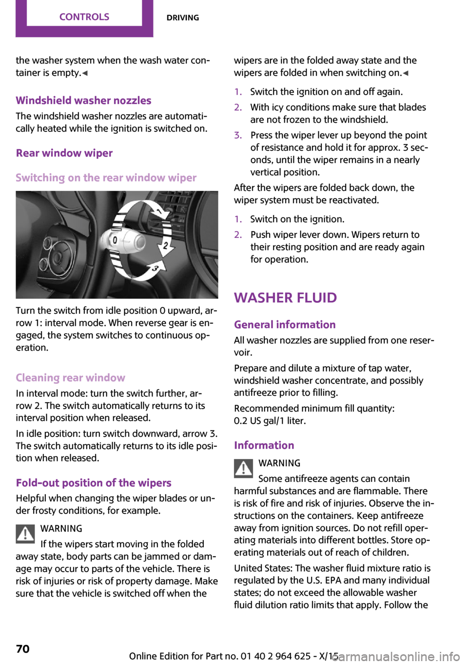
Turn the switch from idle position 0 upward, ar‐
row 1: interval mode. When reverse gear is en‐
gaged, the system switches to continuous op‐
eration.
Cleaning rear window In interval mode: turn the switch further, ar‐
row 2. The switch automatically returns to its
interval position when released.
In idle position: turn switch downward, arrow 3.
The switch automatically returns to its idle posi‐
tion when released.
Fold-out position of the wipers
Helpful when changing the wiper blades or un‐
der frosty conditions, for example.
WARNING
If the wipers start moving in the folded
away state, body parts can be jammed or dam‐
age may occur to parts of the vehicle. There is
risk of injuries or risk of property damage. Make
sure that the vehicle is switched off when the
wipers are in the folded away state and the
wipers are folded in when switching on. ◀1.Switch the ignition on and off again.2.With icy conditions make sure that blades
are not frozen to the windshield.3.Press the wiper lever up beyond the point
of resistance and hold it for approx. 3 sec‐
onds, until the wiper remains in a nearly
vertical position.
After the wipers are folded back down, the
wiper system must be reactivated.
1.Switch on the ignition.2.Push wiper lever down. Wipers return to
their resting position and are ready again
for operation.
Washer fluid
General information All washer nozzles are supplied from one reser‐
voir.
Prepare and dilute a mixture of tap water,
windshield washer concentrate, and possibly
antifreeze prior to filling.
Recommended minimum fill quantity:
0.2 US gal/1 liter.
Information WARNING
Some antifreeze agents can contain
harmful substances and are flammable. There
is risk of fire and risk of injuries. Observe the in‐
structions on the containers. Keep antifreeze
away from ignition sources. Do not refill oper‐
ating materials into different bottles. Store op‐
erating materials out of reach of children.
United States: The washer fluid mixture ratio is
regulated by the U.S. EPA and many individual
states; do not exceed the allowable washer
fluid dilution ratio limits that apply. Follow the
Seite 70CONTROLSDriving70
Online Edition for Part no. 01 40 2 964 625 - X/15
Page 71 of 248
usage instructions on the washer fluid con‐
tainer.
Use of BMW’s Windshield Washer Concentrate
or the equivalent is recommended. ◀
WARNING
Washer fluid can ignite and catch fire on
contact with hot engine parts. There is risk of
injuries or risk of property damage. Only add
washer fluid when the engine is cooled down.
Next, fully close the lid of the washer fluid res‐
ervoir. ◀
CAUTION
Silicon-containing additives in the washer
fluid for the water-repelling effect on the win‐
dows can lead to damage to the washing sys‐
tem. There is risk of property damage. Do not
add silicon-containing additives to the washer
fluid. ◀
CAUTION
The use of undiluted and different wind‐
shield washer concentrate or antifreeze can
lead to damage to the washing system. There is
risk of property damage. Dilute windshield
washer concentrate or antifreeze prior to filling.
Observe the information and mixing ratios pro‐
vided on the containers. Do not mix windshield
washer concentrates of different manufactur‐
ers. ◀
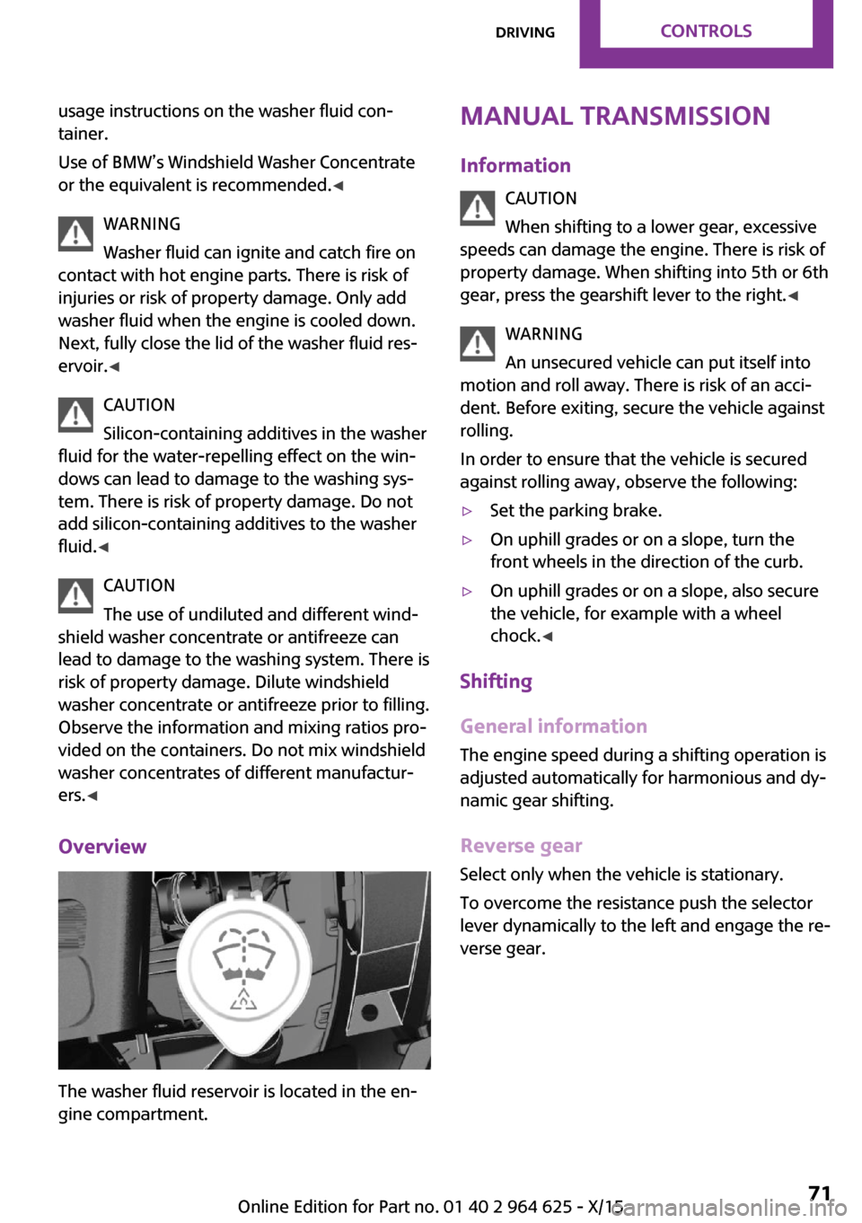
Overview
The washer fluid reservoir is located in the en‐
gine compartment.
Manual transmission
Information CAUTION
When shifting to a lower gear, excessive
speeds can damage the engine. There is risk of
property damage. When shifting into 5th or 6th
gear, press the gearshift lever to the right. ◀
WARNING
An unsecured vehicle can put itself into
motion and roll away. There is risk of an acci‐
dent. Before exiting, secure the vehicle against
rolling.
In order to ensure that the vehicle is secured
against rolling away, observe the following:▷Set the parking brake.▷On uphill grades or on a slope, turn the
front wheels in the direction of the curb.▷On uphill grades or on a slope, also secure
the vehicle, for example with a wheel
chock. ◀
Shifting
General information
The engine speed during a shifting operation is
adjusted automatically for harmonious and dy‐
namic gear shifting.
Reverse gear
Select only when the vehicle is stationary.
To overcome the resistance push the selector
lever dynamically to the left and engage the re‐
verse gear.
Seite 71DrivingCONTROLS71
Online Edition for Part no. 01 40 2 964 625 - X/15
Page 72 of 248
Steptronic transmissionInformation WARNING
An unsecured vehicle can put itself into
motion and roll away. There is risk of an acci‐
dent. Before exiting, secure the vehicle against
rolling.
In order to ensure that the vehicle is secured
against rolling away, observe the following:▷Set the parking brake.▷On uphill grades or on a slope, turn the
front wheels in the direction of the curb.▷On uphill grades or on a slope, also secure
the vehicle, for example with a wheel
chock. ◀
Selector lever positions
D Drive Selector lever position for normal vehicle oper‐
ation. All gears for forward travel are activated
automatically.
R Reverse Select only when the vehicle is stationary.
N Neutral
The vehicle may roll. Use in automatic car
washes, for example.
P Park
Select only when the vehicle is stationary. The
drive wheels are blocked.
Before exiting the vehicle, make sure that se‐
lector lever position P is set. Otherwise, the ve‐
hicle may begin to move.
Kickdown
Kickdown is used to achieve maximum driving
performance. Step on the accelerator pedal be‐
yond the resistance point at the full throttle po‐
sition.
Engaging selector lever positions
To prevent the vehicle from creeping after you
select a gear, maintain pressure on the brake
pedal until you are ready to start.
The selector lever can only be taken out of se‐
lector lever position P if the ignition is on or the
engine is running.
With the vehicle stationary, depress the brake
pedal before shifting out of selector lever posi‐
tion P or N; otherwise, the shift block will not be
deactivated and the shift command will not be
executed.
A block prevents the inadvertent switching to
selector lever position P or R or the inadvertent
change from selector lever position P.
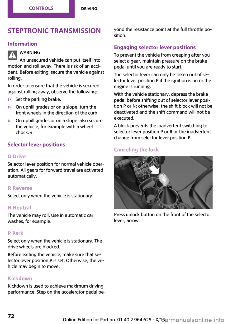
Canceling the lock
Press unlock button on the front of the selector
lever, arrow.
Seite 72CONTROLSDriving72
Online Edition for Part no. 01 40 2 964 625 - X/15
Page 76 of 248
DisplaysVehicle features and op‐tions
This chapter describes all standard, country-
specific and optional features offered with the
series. It also describes features that are notnecessarily available in your car, e. g., due to
the selected options or country versions. This
also applies to safety-related functions and sys‐
tems. The respectively applicable country provi‐
sions must be observed when using the respec‐
tive features and systems.
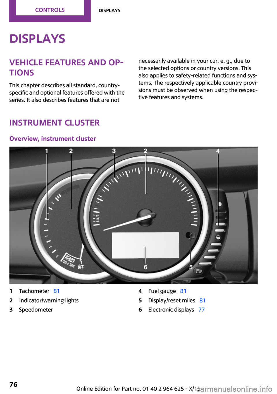
Instrument cluster
Overview, instrument cluster
1Tachometer 812Indicator/warning lights3Speedometer4Fuel gauge 815Display/reset miles 816Electronic displays 77Seite 76CONTROLSDisplays76
Online Edition for Part no. 01 40 2 964 625 - X/15
Page 77 of 248
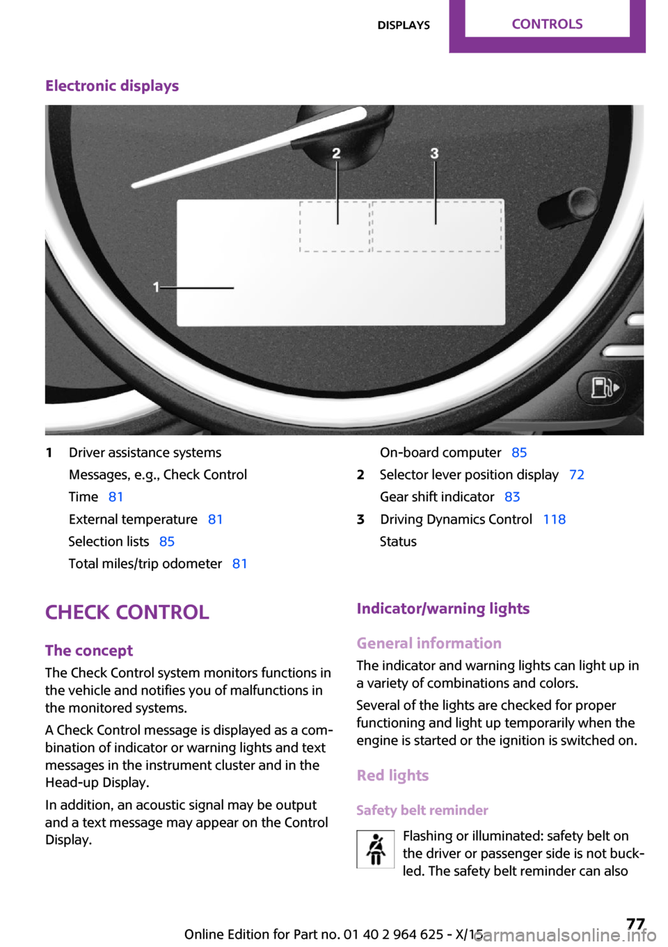
Electronic displays1Driver assistance systems
Messages, e.g., Check Control
Time 81
External temperature 81
Selection lists 85
Total miles/trip odometer 81On-board computer 852Selector lever position display 72
Gear shift indicator 833Driving Dynamics Control 118
StatusCheck Control
The concept
The Check Control system monitors functions in
the vehicle and notifies you of malfunctions in the monitored systems.
A Check Control message is displayed as a com‐
bination of indicator or warning lights and text
messages in the instrument cluster and in the
Head-up Display.
In addition, an acoustic signal may be output
and a text message may appear on the Control Display.Indicator/warning lights
General information
The indicator and warning lights can light up in
a variety of combinations and colors.
Several of the lights are checked for proper
functioning and light up temporarily when the
engine is started or the ignition is switched on.
Red lights Safety belt reminder Flashing or illuminated: safety belt on
the driver or passenger side is not buck‐
led. The safety belt reminder can alsoSeite 77DisplaysCONTROLS77
Online Edition for Part no. 01 40 2 964 625 - X/15
Page 78 of 248
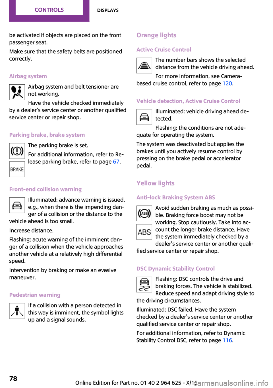
be activated if objects are placed on the front
passenger seat.
Make sure that the safety belts are positioned
correctly.
Airbag system Airbag system and belt tensioner are
not working.
Have the vehicle checked immediately
by a dealer’s service center or another qualified
service center or repair shop.
Parking brake, brake system The parking brake is set.
For additional information, refer to Re‐
lease parking brake, refer to page 67.
Front-end collision warning Illuminated: advance warning is issued,
e.g., when there is the impending dan‐
ger of a collision or the distance to the
vehicle ahead is too small.
Increase distance.
Flashing: acute warning of the imminent dan‐
ger of a collision when the vehicle approaches
another vehicle at a relatively high differential
speed.
Intervention by braking or make an evasive
maneuver.
Pedestrian warning If a collision with a person detected in
this way is imminent, the symbol lights
up and a signal sounds.Orange lights
Active Cruise Control The number bars shows the selected
distance from the vehicle driving ahead.
For more information, see Camera-
based cruise control, refer to page 120.
Vehicle detection, Active Cruise Control Illuminated: vehicle driving ahead de‐
tected.
Flashing: the conditions are not ade‐
quate for operating the system.
The system was deactivated but applies the
brakes until you actively resume control by
pressing on the brake pedal or accelerator
pedal.
Yellow lights Anti-lock Braking System ABS Avoid sudden braking as much as possi‐
ble. Braking force boost may not be
working. Stop cautiously. Take into ac‐
count the longer brake distance. Have
the system immediately checked by a
dealer’s service center or another quali‐
fied service center or repair shop.
DSC Dynamic Stability Control Flashing: DSC controls the drive and
braking forces. The vehicle is stabilized.
Reduce speed and adapt driving style to
the driving circumstances.
Illuminated: DSC failed. Have the system
checked by a dealer’s service center or another
qualified service center or repair shop.
For additional information, refer to Dynamic
Stability Control DSC, refer to page 116.Seite 78CONTROLSDisplays78
Online Edition for Part no. 01 40 2 964 625 - X/15
Page 80 of 248
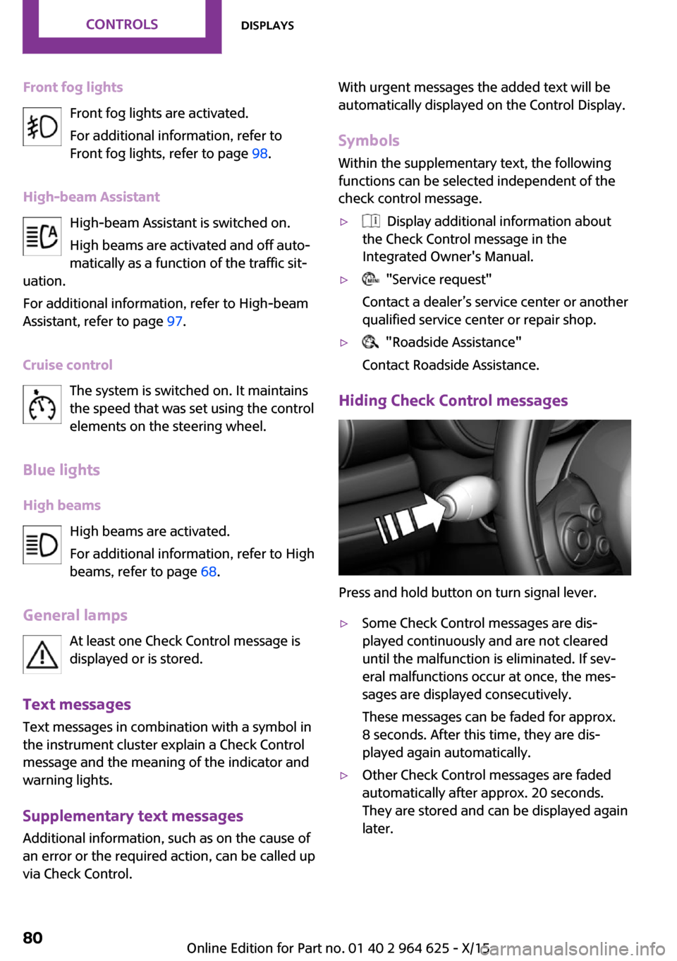
Front fog lightsFront fog lights are activated.
For additional information, refer to
Front fog lights, refer to page 98.
High-beam Assistant High-beam Assistant is switched on.
High beams are activated and off auto‐
matically as a function of the traffic sit‐
uation.
For additional information, refer to High-beam
Assistant, refer to page 97.
Cruise control The system is switched on. It maintains
the speed that was set using the control
elements on the steering wheel.
Blue lights
High beams High beams are activated.
For additional information, refer to High
beams, refer to page 68.
General lamps At least one Check Control message is
displayed or is stored.
Text messages
Text messages in combination with a symbol in
the instrument cluster explain a Check Control
message and the meaning of the indicator and
warning lights.
Supplementary text messages
Additional information, such as on the cause of
an error or the required action, can be called up
via Check Control.With urgent messages the added text will be
automatically displayed on the Control Display.
Symbols
Within the supplementary text, the following
functions can be selected independent of the
check control message.▷ Display additional information about
the Check Control message in the
Integrated Owner's Manual.▷ "Service request"
Contact a dealer’s service center or another
qualified service center or repair shop.▷ "Roadside Assistance"
Contact Roadside Assistance.
Hiding Check Control messages
Press and hold button on turn signal lever.
▷Some Check Control messages are dis‐
played continuously and are not cleared
until the malfunction is eliminated. If sev‐
eral malfunctions occur at once, the mes‐
sages are displayed consecutively.
These messages can be faded for approx.
8 seconds. After this time, they are dis‐
played again automatically.▷Other Check Control messages are faded
automatically after approx. 20 seconds.
They are stored and can be displayed again
later.Seite 80CONTROLSDisplays80
Online Edition for Part no. 01 40 2 964 625 - X/15
Page 81 of 248
Displaying stored Check Control
messages
On the Control Display:1. "Vehicle info"2."Vehicle status"3. "Check Control"4.Select the text message.
Messages after trip completion
Special messages displayed while driving are
displayed again after the ignition is switched
off.
Fuel gauge Vehicle tilt position may cause
the display to vary.
The arrow beside the fuel pump
symbol shows which side of the
vehicle the fuel filler flap is on.
Hints on refueling, refer to page 176.
Tachometer
Always avoid engine speeds in the red warning
field. In this range, the fuel supply is interrupted
to protect the engine.
Odometer and trip odom‐
eter
The concept
Odometer and trip odometer are displayed in
the instrument cluster.
Resetting the trip odometer
Press the knob.▷The odometer is displayed
when the ignition is switched
off.▷When the ignition is switched
on, the trip odometer is re‐
set.
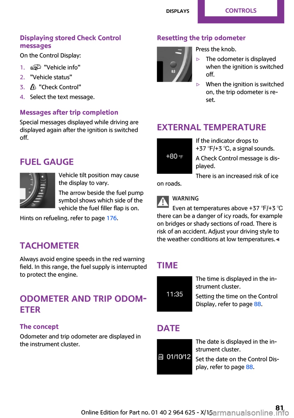
External temperature
If the indicator drops to
+37 ℉/+3 ℃, a signal sounds.
A Check Control message is dis‐
played.
There is an increased risk of ice
on roads.
WARNING
Even at temperatures above +37 ℉/+3 ℃
there can be a danger of icy roads, for example
on bridges or shady sections of road. There is
risk of an accident. Adjust your driving style to
the weather conditions at low temperatures. ◀
Time The time is displayed in the in‐
strument cluster.
Setting the time on the Control
Display, refer to page 88.
Date The date is displayed in the in‐strument cluster.
Set the date on the Control Dis‐
play, refer to page 88.
Seite 81DisplaysCONTROLS81
Online Edition for Part no. 01 40 2 964 625 - X/15
Page 83 of 248
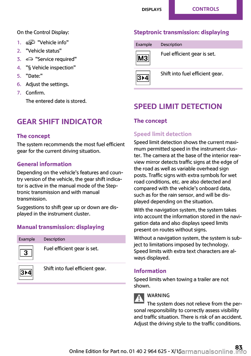
On the Control Display:1. "Vehicle info"2."Vehicle status"3. "Service required"4."§ Vehicle inspection"5."Date:"6.Adjust the settings.7.Confirm.
The entered date is stored.
Gear shift indicator
The concept
The system recommends the most fuel efficient
gear for the current driving situation.
General information Depending on the vehicle's features and coun‐
try version of the vehicle, the gear shift indica‐
tor is active in the manual mode of the Step‐
tronic transmission and with manual
transmission.
Suggestions to shift gear up or down are dis‐
played in the instrument cluster.
Manual transmission: displaying
ExampleDescriptionFuel efficient gear is set.Shift into fuel efficient gear.Steptronic transmission: displayingExampleDescriptionFuel efficient gear is set.Shift into fuel efficient gear.
Speed limit detection
The concept
Speed limit detection
Speed limit detection shows the current maxi‐
mum permitted speed in the instrument clus‐
ter. The camera at the base of the interior rear‐
view mirror detects traffic signs at the edge of
the road as well as variable overhead sign
posts. Traffic signs with extra symbols for wet
road conditions, etc. are also detected and
compared with the vehicle's onboard data,
such as for the rain sensor, and will be dis‐
played depending on the situation.
With the navigation system, the system takes
into account the information stored in the navi‐
gation data and also displays speed limits
present on routes without signs.
Without a navigation system, the system is sub‐
ject to limitations imposed by technology.
Speed limits with extra text characters are al‐
ways displayed.
Information
Speed limits when towing a trailer are not
shown.
WARNING
The system does not relieve from the per‐
sonal responsibility to correctly assess visibility
and traffic situation. There is risk of an accident.
Adjust the driving style to the traffic conditions.
Seite 83DisplaysCONTROLS83
Online Edition for Part no. 01 40 2 964 625 - X/15
Page 88 of 248
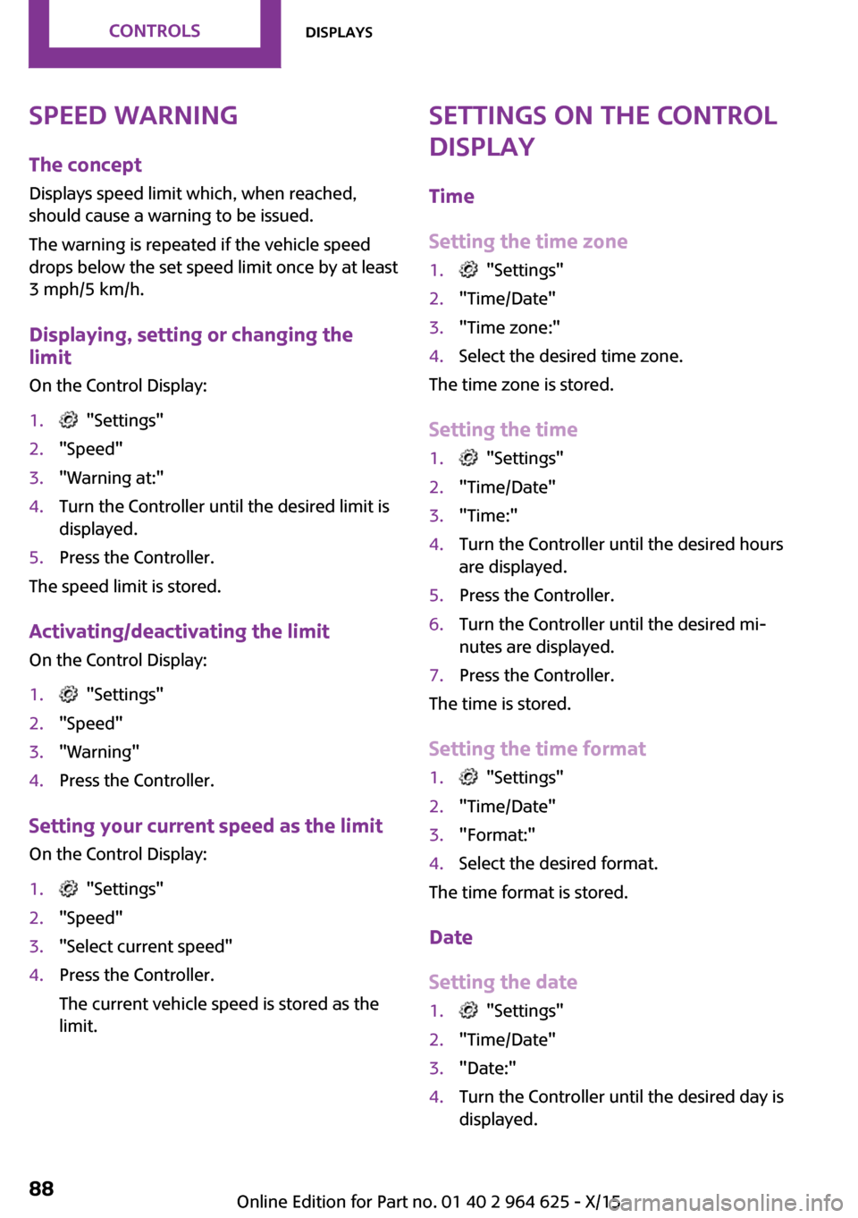
Speed warning
The concept
Displays speed limit which, when reached,
should cause a warning to be issued.
The warning is repeated if the vehicle speed
drops below the set speed limit once by at least
3 mph/5 km/h.
Displaying, setting or changing the
limit
On the Control Display:1. "Settings"2."Speed"3."Warning at:"4.Turn the Controller until the desired limit is
displayed.5.Press the Controller.
The speed limit is stored.
Activating/deactivating the limit On the Control Display:
1. "Settings"2."Speed"3."Warning"4.Press the Controller.
Setting your current speed as the limit On the Control Display:
1. "Settings"2."Speed"3."Select current speed"4.Press the Controller.
The current vehicle speed is stored as the
limit.Settings on the Control
Display
Time
Setting the time zone1. "Settings"2."Time/Date"3."Time zone:"4.Select the desired time zone.
The time zone is stored.
Setting the time
1. "Settings"2."Time/Date"3."Time:"4.Turn the Controller until the desired hours
are displayed.5.Press the Controller.6.Turn the Controller until the desired mi‐
nutes are displayed.7.Press the Controller.
The time is stored.
Setting the time format
1. "Settings"2."Time/Date"3."Format:"4.Select the desired format.
The time format is stored.
Date
Setting the date
1. "Settings"2."Time/Date"3."Date:"4.Turn the Controller until the desired day is
displayed.Seite 88CONTROLSDisplays88
Online Edition for Part no. 01 40 2 964 625 - X/15