warning MINI 3 door 2015 Manual Online
[x] Cancel search | Manufacturer: MINI, Model Year: 2015, Model line: 3 door, Model: MINI 3 door 2015Pages: 248, PDF Size: 5.43 MB
Page 156 of 248
Grasp the cargo floor panel in the rear and fold
slightly upward. Next, pull it backward from the
supports.
The cargo floor panel can be removed from the
trunk above the tail lamps.
Lower position
▷Larger objects can be transported.▷Space for smaller objects remains between
the fixed and variable trunk floor.
Folded up position
WARNING
Improper use of the variable cargo floor
panel can lead to a danger of objects flying
about during braking and evasive maneuvers.
There is risk of injuries and risk of property
damage.
▷Do not use the variable cargo floor panel to
separate the cargo area and vehicle interior
in the sense of a partition net.▷Only use the variable cargo floor in the
folded-up position when the backrests are
folded up and locked.▷Always secure cargo against shifting, using
straps, belts and lashing eyes, for exam‐
ple. ◀
Fold up the cargo floor panel in the lower posi‐
tion and push it behind the locks, arrow.
You've reached the maximum cargo height.
Upper position
▷With the backrests folded down, a long, flat
loading surface is produced.▷For 3-door models:
Maximum load in this position:
330 lbs/150 kg.▷For 5-door models:
Maximum load in this position:
441 lbs/200 kg.▷Space for objects remains between the
fixed and variable trunk floor.Seite 156CONTROLSStorage compartments156
Online Edition for Part no. 01 40 2 964 625 - X/15
Page 160 of 248
Things to remember when drivingVehicle features and op‐tions
This chapter describes all standard, country-
specific and optional features offered with the
series. It also describes features that are not
necessarily available in your car, e. g., due to
the selected options or country versions. This
also applies to safety-related functions and sys‐
tems. The respectively applicable country provi‐
sions must be observed when using the respec‐
tive features and systems.
Breaking-in period General information Moving parts need time to adjust to one an‐
other (break-in time).
The following instructions will help accomplish
a long vehicle life and good efficiency.
During break-in, do not use the Launch Control,
refer to page 74.
Information WARNING
Due to new parts and components, safety
and driver assistance systems can react with a
delay. There is risk of an accident. After instal‐
ling new parts or with a new vehicle, drive con‐
servatively and interfere early if necessary. Ob‐
serve the break-in procedures of the respective
parts and components. ◀
Engine, transmission, and axle drive
Up to 1,200 miles/2,000 km Do not exceed the maximum engine and road
speed:▷For gasoline engine 4,500 rpm and
100 mph/160 km/h.
Avoid full load or kickdown under all circum‐
stances.
From 1,200 miles/2,000 km
The engine and vehicle speed can gradually be
increased.
Tires Tire traction is not optimal due to manufactur‐
ing circumstances when tires are brand-new;
they achieve their full traction potential after a
break-in time.
Drive conservatively for the first
200 miles/300 km.
Brake system Brakes require an initial break-in period of ap‐
prox. 300 miles/500 km to achieve optimal per‐
formance between brake discs and brake pads.
Drive moderately during this break-in period.
Clutch
The function of the clutch reaches its optimal
level only after a distance driven of approx.
300 miles/500 km. During this break-in period,
engage the clutch gently.
Following part replacement
The same break-in procedures should be ob‐
served if any of the components above-men‐
tioned have to be renewed in the course of the
vehicle's operating life.
Seite 160DRIVING TIPSThings to remember when driving160
Online Edition for Part no. 01 40 2 964 625 - X/15
Page 161 of 248
General driving notes
Closing the tailgate WARNING
An open tailgate protrudes from the vehi‐
cle and can endanger occupants and other traf‐
fic participants or damage the vehicle in the
event of an accident, braking or evasive ma‐
neuvers. In addition, exhaust fumes may enter
the vehicle interior. There is risk of injuries or
risk of property damage. Do not drive with the
tailgate open. ◀
If driving with the tailgate open cannot be
avoided:▷Close all windows and the glass sunroof.▷Greatly increase the air flow from the vents.▷Drive moderately.
Hot exhaust system
WARNING
During driving operation, high tempera‐
tures can occur underneath the body, for ex‐
ample caused by the exhaust gas system. If
combustible materials, such as leaves or grass,
come in contact with hot parts of the exhaust
gas system, these materials can ignite. There is
risk of injuries or risk of property damage.
Do not remove the heat shields installed and
never apply undercoating to them. Make sure
that no combustible materials can come in con‐
tact with hot vehicle parts in driving operation,
idle or during parking. Do not touch the hot ex‐
haust system. ◀
Mobile communication devices in the vehicle
WARNING
Vehicle electronics and mobile phones
can influence one another. There is radiation
due to the send operations of mobile phones.
There is risk of injuries or risk of property dam‐
age. If possible, in the car's interior use only
mobile phones with direct connections to an
exterior antenna in order to exclude mutual
disturbance and deflect the radiation from the
car's interior. ◀
Hydroplaning On wet or slushy roads, a wedge of water can
form between the tires and road surface.
This phenomenon is referred to as hydroplan‐
ing. It is characterized by a partial or complete
loss of contact between the tires and the road
surface, ultimately undermining your ability to
steer and brake the vehicle.
Driving through water CAUTION
When driving too quickly through too
deep water, water can enter into the engine compartment, the electrical system or the
transmission. There is risk of property damage.
When driving through water, do not exceed the
maximum indicated water level and the maxi‐
mum speed for driving through water. ◀
When driving through water, observe the fol‐
lowing:▷Drive through calm water only.▷Drive through water only if it is not deeper
than maximum 9.8 inches/25 cm.▷Drive through water no faster than walking
speed, up to 3 mph/5 km/h.
Braking safely
Your vehicle is equipped with ABS as a standard
feature.
Perform an emergency stop in situations that require such.
Steering is still responsive. You can still avoid
any obstacles with a minimum of steering ef‐
fort.
Pulsation of the brake pedal and sounds from
the hydraulic circuits indicate that ABS is in its
active mode.
Seite 161Things to remember when drivingDRIVING TIPS161
Online Edition for Part no. 01 40 2 964 625 - X/15
Page 162 of 248
Objects in the area around the pedalsWARNING
Objects in the driver's floor area can limit
the pedal distance or block a depressed pedal.
There is risk of an accident. Stow objects in the
vehicle such that they are secured and cannot
enter into the driver's floor area. Use floor mats
that are suitable for the vehicle and can be
safely attached to the floor. Do not use loose
floor mats and do not layer several floor mats.
Make sure that there is sufficient clearance for
the pedals. Ensure that the floor mats are se‐
curely fastened again after they were removed,
for example for cleaning. ◀
Driving in wet conditions When roads are wet, salted, or in heavy rain,
press brake pedal ever so gently every few
miles.
Ensure that this action does not endanger other
traffic.
The heat generated in this process helps dry
the brake discs and pads.
In this way braking efficiency will be available
when you need it.
Hills WARNING
Light but consistent brake pressure can
lead to high temperatures, brakes wearing out
and possibly even brake failure. There is risk of
an accident. Avoid placing excessive stress on
the brake system. ◀
WARNING
In idle or with the engine switched off,
safety-relevant functions are restricted or not
available anymore, for example braking effect
of the engine or braking force and steering
support. There is risk of an accident. Do not
drive in idle or with the engine switched off. ◀
Drive long or steep downhill gradients in the
gear that requires least braking efforts. Other‐wise the brakes may overheat and reduce
brake efficiency.
You can increase the engine's braking effect by
shifting down, going all the way to first gear, if
needed.
Brake disc corrosion Corrosion on the brake discs and contamina‐
tion on the brake pads are furthered by:▷Low mileage.▷Extended periods when the vehicle is not
used at all.▷Infrequent use of the brakes.
Corrosion will built up when the maximum
pressure applied to the brake pads during brak‐
ing is not reached - thus discs don't get
cleaned.
Corrosion buildup on the brake discs will cause
a pulsating effect on the brakes in their re‐
sponse - generally that cannot be corrected.
Condensation under the parked vehicle When using the automatic climate control, con‐
densation water develops collecting under‐
neath the vehicle.
Ground clearance CAUTION
If ground clearance is insufficient, there
might be contact with the front or rear spoiler
for example when driving over curbs or enter‐
ing into underground car parking garages.
There is risk of property damage. Ensure that
there is sufficient ground clearance available. ◀
Seite 162DRIVING TIPSThings to remember when driving162
Online Edition for Part no. 01 40 2 964 625 - X/15
Page 163 of 248
LoadingVehicle features and op‐tions
This chapter describes all standard, country-
specific and optional features offered with the
series. It also describes features that are not
necessarily available in your car, e. g., due to
the selected options or country versions. This
also applies to safety-related functions and sys‐
tems. The respectively applicable country provi‐
sions must be observed when using the respec‐
tive features and systems.
Information WARNING
High gross weight can overheat the tires,
damage them, and cause a sudden drop in tire
inflation pressure. There is risk of an accident.
Pay attention to the permitted load capacity of
the tires and never exceed the permitted gross
weight. ◀
WARNING
Loose objects or devices with a cable
connection to the vehicle, for example mobile
phones, can be thrown into the car's interior
while driving, for example in the event of an
accident or during braking and evasive maneu‐
vers. There is risk of injuries. Secure loose ob‐
jects or devices with a cable connection to the
vehicle in the car's interior. ◀
CAUTION
Fluids in the cargo area can cause dam‐
age. There is risk of property damage. Make
sure that no fluids leak in the cargo area. ◀Determining the load
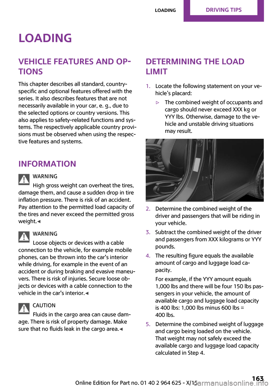
limit1.Locate the following statement on your ve‐
hicle’s placard:▷The combined weight of occupants and
cargo should never exceed XXX kg or
YYY lbs. Otherwise, damage to the ve‐
hicle and unstable driving situations
may result.2.Determine the combined weight of the
driver and passengers that will be riding in
your vehicle.3.Subtract the combined weight of the driver
and passengers from XXX kilograms or YYY
pounds.4.The resulting figure equals the available
amount of cargo and luggage load ca‐
pacity.
For example, if the YYY amount equals
1,000 lbs and there will be four 150 lbs pas‐
sengers in your vehicle, the amount of
available cargo and luggage load capacity
is 400 lbs: 1,000 lbs minus 600 lbs =
400 lbs.5.Determine the combined weight of luggage
and cargo being loaded on the vehicle.
That weight may not safely exceed the
available cargo and luggage load capacity
calculated in Step 4.Seite 163LoadingDRIVING TIPS163
Online Edition for Part no. 01 40 2 964 625 - X/15
Page 164 of 248
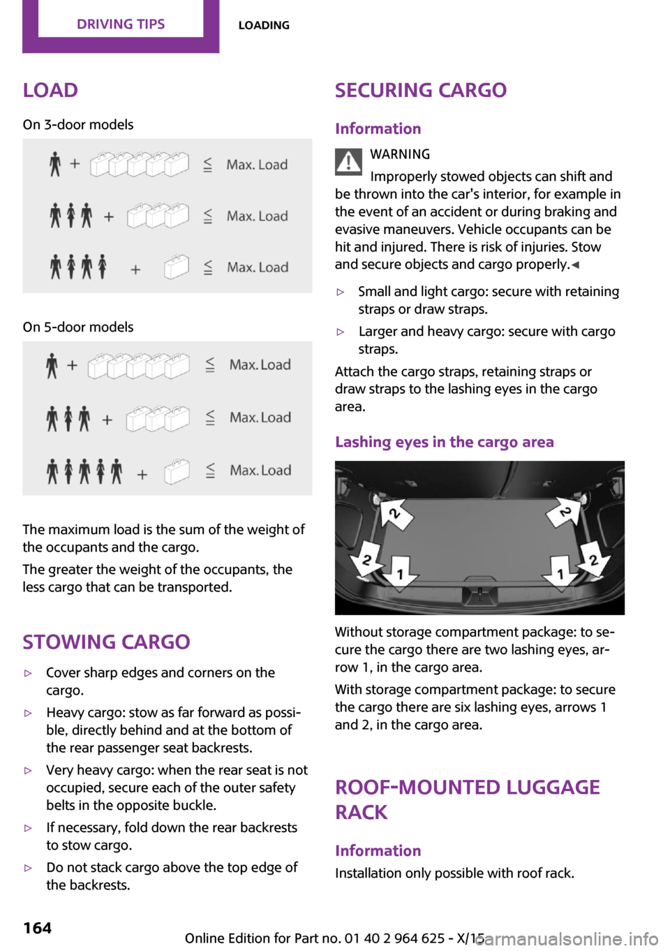
LoadOn 3-door modelsOn 5-door models
The maximum load is the sum of the weight of
the occupants and the cargo.
The greater the weight of the occupants, the
less cargo that can be transported.
Stowing cargo
▷Cover sharp edges and corners on the
cargo.▷Heavy cargo: stow as far forward as possi‐
ble, directly behind and at the bottom of
the rear passenger seat backrests.▷Very heavy cargo: when the rear seat is not
occupied, secure each of the outer safety
belts in the opposite buckle.▷If necessary, fold down the rear backrests
to stow cargo.▷Do not stack cargo above the top edge of
the backrests.Securing cargo
Information WARNING
Improperly stowed objects can shift and
be thrown into the car's interior, for example in
the event of an accident or during braking and
evasive maneuvers. Vehicle occupants can be
hit and injured. There is risk of injuries. Stow
and secure objects and cargo properly. ◀▷Small and light cargo: secure with retaining
straps or draw straps.▷Larger and heavy cargo: secure with cargo
straps.
Attach the cargo straps, retaining straps or
draw straps to the lashing eyes in the cargo
area.
Lashing eyes in the cargo area
Without storage compartment package: to se‐
cure the cargo there are two lashing eyes, ar‐
row 1, in the cargo area.
With storage compartment package: to secure
the cargo there are six lashing eyes, arrows 1
and 2, in the cargo area.
Roof-mounted luggage
rack
Information Installation only possible with roof rack.
Seite 164DRIVING TIPSLoading164
Online Edition for Part no. 01 40 2 964 625 - X/15
Page 168 of 248
The Coasting driving condition is enabled under
certain conditions.
Under certain conditions the engine is auto‐
matically decoupled from the transmission in
selector lever position D. The vehicle continues
traveling with the engine idling to reduce fuel
consumption. Selector lever position D remains
engaged. An indicator provides information
about the distance traveled in Coasting mode.
In addition, context-sensitive instructions are
displayed to assist with an optimized fuel con‐
sumption driving style.
The achieved extended range is displayed in
the instrument cluster.
Overview The system includes the following MINIMAL
functions and displays:▷GREEN bonus range, refer to page 169.▷GREEN tips driving instruction, refer to
page 169.▷GREEN climate control, refer to page 168.▷MINIMALISM analyzer, refer to page 171.▷Coasting driving condition, refer to
page 170.
Activating GREEN Mode
Turn Driving Dynamics Control to
the right until GREEN Mode is
displayed in the instrument clus‐
ter.
Configuring GREEN Mode
Via the Driving Dynamics Control
1.Activating GREEN Mode.2."Configure GREEN"3.Configure the program.
Via onboard monitor:
1. "Settings"2."GREEN Mode"
Or
1. "Settings"2."Driving mode"3."Configure GREEN"
Configure the program.
GREEN tip
▷"Tip at:"
Set the GREEN Mode speed at which a
GREEN Mode tip is to be displayed.▷"GREEN speed warning":
Displays a reminder when the set GREEN
Mode speed is exceeded.
Coasting
Fuel-efficiency can be optimized by disengag‐
ing the engine and Coasting, refer to page 170,
with the engine idling.
This function is only available in GREEN Mode.
GREEN climate control
"GREEN climate control"
Climate control is set to be fuel-efficient.
By making a slight change to the set tempera‐
ture, or adjusting the rate of heating or cooling
of the car's interior fuel consumption can be
economized.
The outputs of the seat heater and the exterior
Additionally heat output to seats and exterior
mirror is reduced.
Exterior mirror heat is available when outside
temperatures are very low.
GREEN potential
The percentage of potential savings that can be
achieved with the current configuration is dis‐
played.
Seite 168DRIVING TIPSSaving fuel168
Online Edition for Part no. 01 40 2 964 625 - X/15
Page 176 of 248
RefuelingVehicle features and op‐
tions
This chapter describes all standard, country-
specific and optional features offered with the
series. It also describes features that are not necessarily available in your car, e. g., due to
the selected options or country versions. This
also applies to safety-related functions and sys‐
tems. The respectively applicable country provi‐
sions must be observed when using the respec‐
tive features and systems.
Information Observe the fuel recommendation, refer to
page 178, prior to refueling.
CAUTION
With a range of less than 30 miles/50 km
it is possible that the engine will no longer have
sufficient fuel. Engine functions are not ensured
anymore. There is risk of property damage. Re‐
fuel promptly. ◀
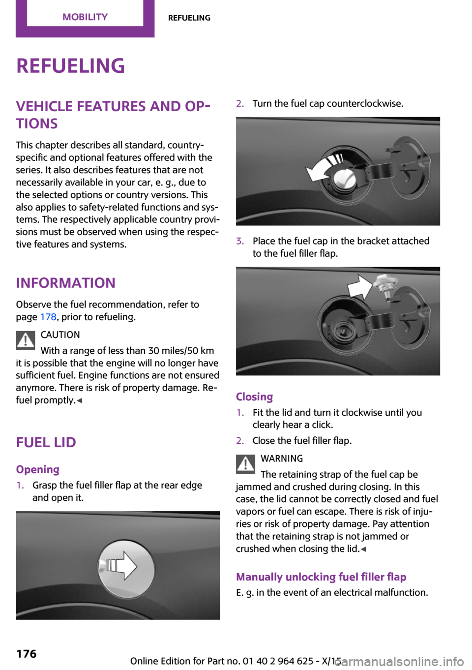
Fuel lid Opening1.Grasp the fuel filler flap at the rear edge
and open it.2.Turn the fuel cap counterclockwise.3.Place the fuel cap in the bracket attached
to the fuel filler flap.
Closing
1.Fit the lid and turn it clockwise until you
clearly hear a click.2.Close the fuel filler flap.
WARNING
The retaining strap of the fuel cap be
jammed and crushed during closing. In this
case, the lid cannot be correctly closed and fuel
vapors or fuel can escape. There is risk of inju‐
ries or risk of property damage. Pay attention
that the retaining strap is not jammed or
crushed when closing the lid. ◀
Manually unlocking fuel filler flap E. g. in the event of an electrical malfunction.
Seite 176MOBILITYRefueling176
Online Edition for Part no. 01 40 2 964 625 - X/15
Page 180 of 248
Wheels and tiresVehicle features and op‐
tions
This chapter describes all standard, country-
specific and optional features offered with the
series. It also describes features that are not
necessarily available in your car, e. g., due to
the selected options or country versions. This
also applies to safety-related functions and sys‐
tems. The respectively applicable country provi‐
sions must be observed when using the respec‐
tive features and systems.
Tire inflation pressure Safety informationThe tire characteristics and tire inflation pres‐
sure influence the following:▷The service life of the tires.▷Road safety.▷Driving comfort.
Checking the tire inflation pressure
WARNING
A tire with low or missing tire inflation
pressure impacts handling, such as steering
and braking response. There is risk of an acci‐
dent. Regularly check the tire inflation pressure,
and correct it as needed, for example twice a
month and before a long trip. ◀
Tires have a natural, consistent loss of tire infla‐
tion pressure.
Tires heat up while driving, and the tire inflation
pressure increases along with the tire's temper‐
ature. The tire inflation pressure specifications
relate to cold tires or tires with the ambient
temperature.
Only check the tire inflation pressure when the
tires are cold. This means after driving no more
than 1.25 miles/2 km or when the vehicle has
been parked for at least 2 hours.
The displays of inflation devices may under-
read by up to 0.1 bar.
For Flat Tire Monitor: after correcting the tire
inflation pressure, reinitialize the Flat Tire Moni‐
tor.
For Tire Pressure Monitor: after correcting the
tire inflation pressure, reset the Tire Pressure
Monitor.▷Reinitialize the Flat Tire Monitor.▷Reinitialize the Tire Pressure Monitor.
Checking the inflation pressure of the
emergency wheel
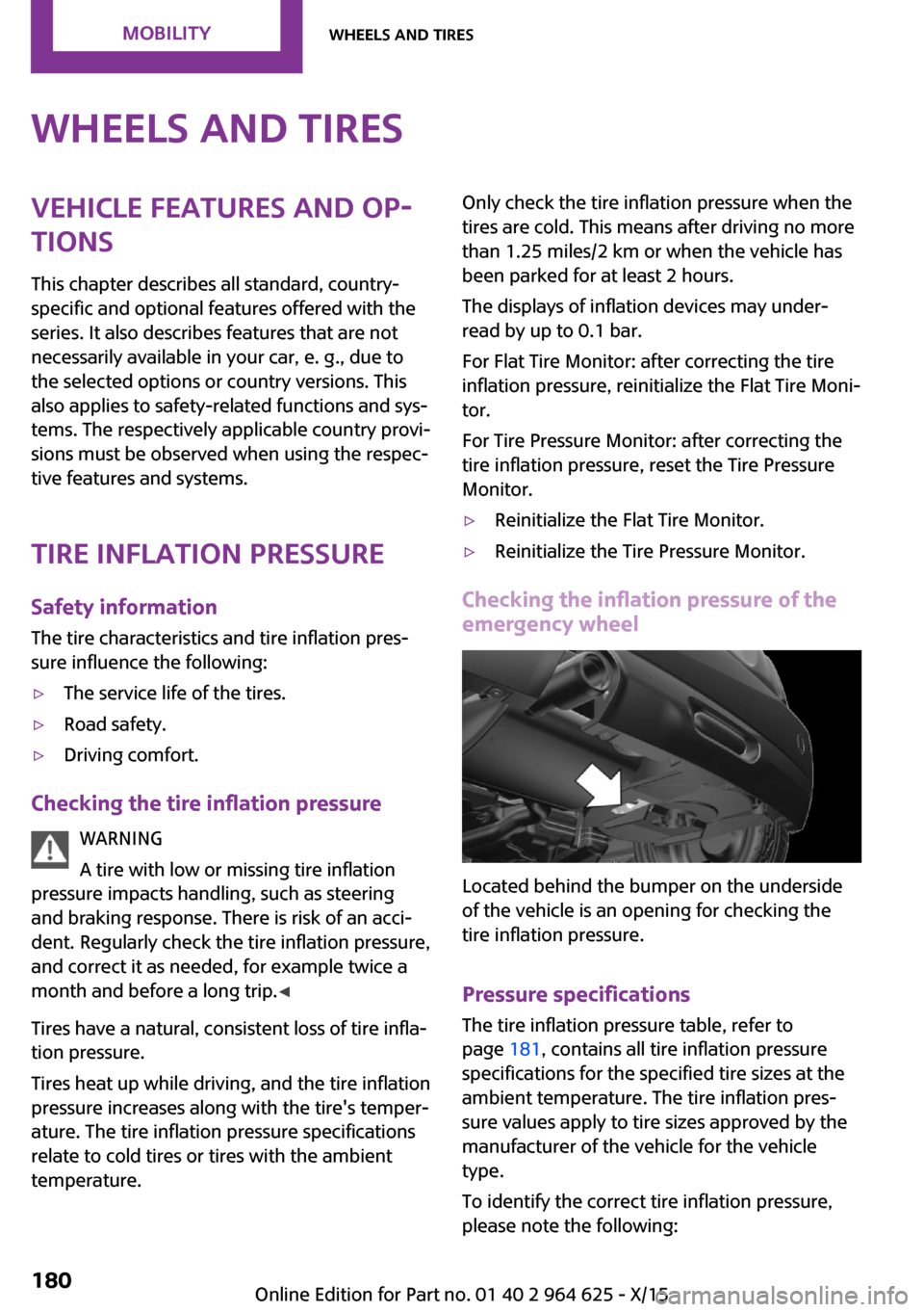
Located behind the bumper on the underside
of the vehicle is an opening for checking the
tire inflation pressure.
Pressure specifications
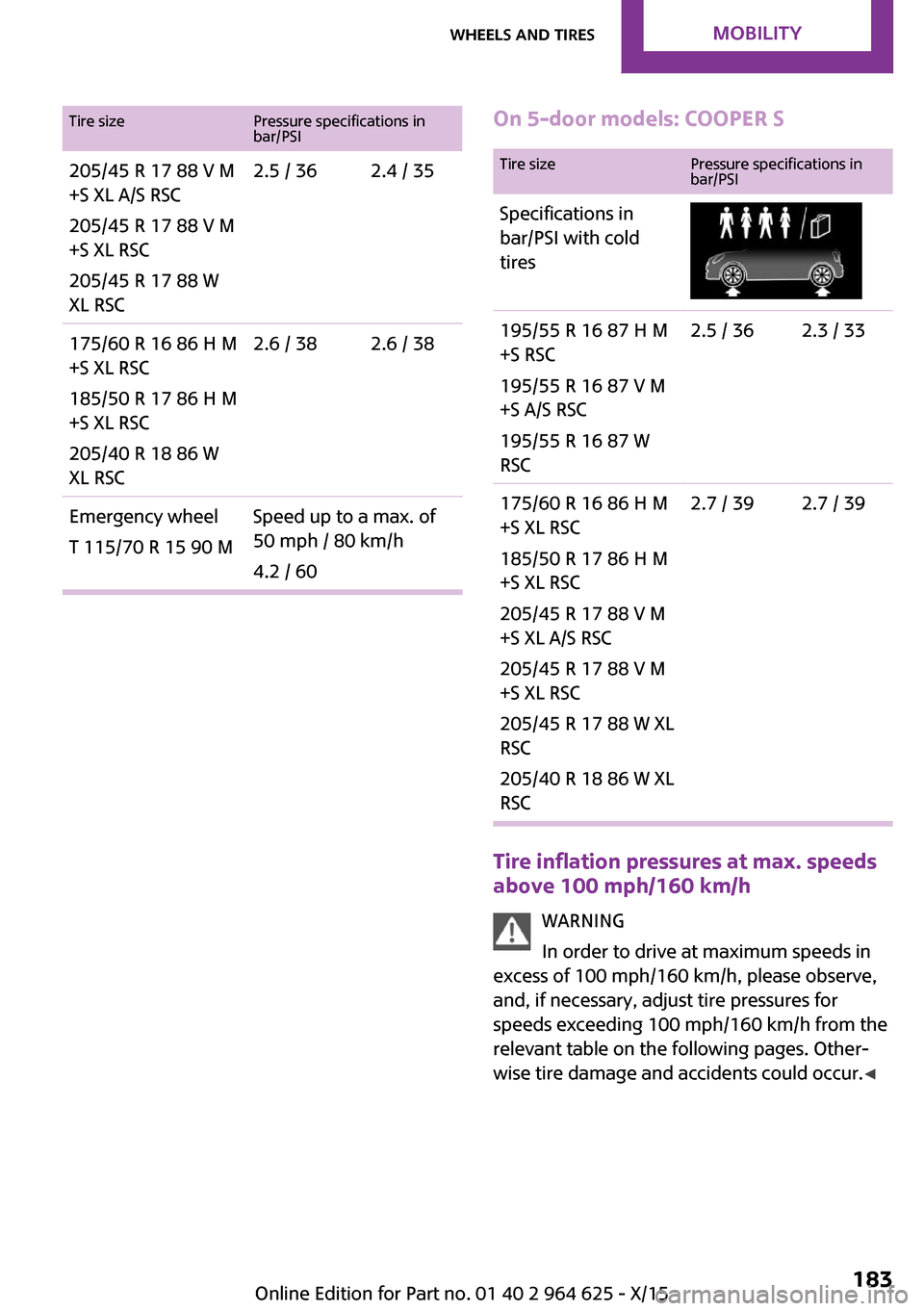
The tire inflation pressure table, refer to
page 181, contains all tire inflation pressure
specifications for the specified tire sizes at the
ambient temperature. The tire inflation pres‐
sure values apply to tire sizes approved by the
manufacturer of the vehicle for the vehicle
type.
To identify the correct tire inflation pressure,
please note the following:
Seite 180MOBILITYWheels and tires180
Online Edition for Part no. 01 40 2 964 625 - X/15
Page 183 of 248
Tire sizePressure specifications in
bar/PSI205/45 R 17 88 V M
+S XL A/S RSC
205/45 R 17 88 V M
+S XL RSC
205/45 R 17 88 W
XL RSC2.5 / 362.4 / 35175/60 R 16 86 H M
+S XL RSC
185/50 R 17 86 H M
+S XL RSC
205/40 R 18 86 W
XL RSC2.6 / 382.6 / 38Emergency wheel
T 115/70 R 15 90 MSpeed up to a max. of
50 mph / 80 km/h
4.2 / 60On 5-door models: COOPER STire sizePressure specifications in
bar/PSISpecifications in
bar/PSI with cold
tires195/55 R 16 87 H M
+S RSC
195/55 R 16 87 V M
+S A/S RSC
195/55 R 16 87 W
RSC2.5 / 362.3 / 33175/60 R 16 86 H M
+S XL RSC
185/50 R 17 86 H M
+S XL RSC
205/45 R 17 88 V M
+S XL A/S RSC
205/45 R 17 88 V M
+S XL RSC
205/45 R 17 88 W XL
RSC
205/40 R 18 86 W XL
RSC2.7 / 392.7 / 39
Tire inflation pressures at max. speeds
above 100 mph/160 km/h
WARNING
In order to drive at maximum speeds in
excess of 100 mph/160 km/h, please observe,
and, if necessary, adjust tire pressures for
speeds exceeding 100 mph/160 km/h from the
relevant table on the following pages. Other‐
wise tire damage and accidents could occur. ◀
Seite 183Wheels and tiresMOBILITY183
Online Edition for Part no. 01 40 2 964 625 - X/15