ECO mode MINI Clubman 2009 Owner's Manual (Mini Connected)
[x] Cancel search | Manufacturer: MINI, Model Year: 2009, Model line: Clubman, Model: MINI Clubman 2009Pages: 218, PDF Size: 3.69 MB
Page 7 of 218
5
MOBILITYAT A GLANCE CONTROLS DRIVING TIPS ENTERTAINMENT NAVIGATION REFERENCE
For your safety
Maintenance and repair
Advanced technology, e.g. the use of
modern materials and powerful electron-
ics, requires specially adapted maintenance and
repair methods. Therefore, have the necessary
work on your MINI only carried out by a MINI
Dealer or a workshop that has specially trained
personnel working in accordance with the spec-
ifications of the MINI manufacturer. If this work
is not carried out properly, there is a danger of
subsequent damage and related safety haz-
ards.<
Parts and accessories
For your own safety, use genuine parts
and accessories approved by the manu-
facturer of the MINI.
When you purchase accessories tested
and approved by the manufacturer of the MINI
and Original MINI Parts, you simultaneously
acquire the assurance that they have been thor-
oughly tested by the manufacturer of the MINI
to ensure optimum performance when installed
on your vehicle.
The manufacturer of the MINI warrants these
parts to be free from defects in material and
workmanship.
The manufacturer of the MINI will not accept any
liability for damage resulting from installation of
parts and accessories not approved by the man-
ufacturer of the MINI.
The manufacturer of the MINI cannot test every
product made by other manufacturers to verify
if it can be used on a MINI safely and without risk
to either the vehicle, its operation, or its occu-
pants.
Original MINI Parts, MINI Accessories and other
products approved by the manufacturer of the
MINI, together with professional advice on using
these items, are available from all MINI Dealers.
Installation and operation of non-MINI
approved accessories such as alarms, radios,
amplifiers, radar detectors, wheels, suspension
components, brake dust shields, telephones, including operation of any mobile phone from
within the vehicle without using an externally
mounted antenna, or transceiver equipment, for
instance, CBs, walkie-talkies, ham radios or sim-
ilar accessories, may cause extensive damage to
the vehicle, compromise its safety, interfere with
the vehicle's electrical system or affect the valid-
ity of the MINI Limited Warranty. See your MINI
Dealer for additional information.<
Maintenance, replacement, or repair of
the emission control devices and systems
may be performed by any automotive repair
establishment or individual using any certified
automotive part.<
California Proposition 65 warning
California law requires us to issue the following
warning:
Engine exhaust and a wide variety of
automobile components and parts,
including components found in the interior fur-
nishings in a vehicle, contain or emit chemicals
known to the State of California to cause cancer
and birth defects and reproductive harm. In
addition, certain fluids contained in vehicles and
certain products of component wear contain or
emit chemicals known to the State of California
to cause cancer and birth defects or other repro-
ductive harm.
Battery posts, terminals and related accessories
contain lead and lead compounds. Wash your
hands after handling.
Used engine oil contains chemicals that have
caused cancer in laboratory animals. Always
protect your skin by washing thoroughly with
soap and water.<
Service and warranty
We recommend that you read this publication
thoroughly.
Your MINI is covered by the following war-
ranties:
>New Vehicle Limited Warranty
>Rust Perforation Limited Warranty
Page 8 of 218
Notes
6
>Federal Emissions System Defect Warranty
>Federal Emissions Performance Warranty
>California Emission Control System Limited
Warranty
Detailed information about these warranties is
listed in the Service and Warranty Information
Booklet for US models or in the Warranty and
Service Guide Booklet for Canadian models.
Your vehicle has been specifically adapted and
designed to meet the particular operating con-
ditions and homologation requirements in your
country and continental region in order to
deliver the full driving pleasure while the vehicle
is operated under those conditions. If you wish
to operate your vehicle in another country or
region, you may be required to adapt your vehi-
cle to meet different prevailing operating condi-
tions and homologation requirements. You
should also be aware of any applicable warranty
limitations or exclusions for such country or
region. In such case, please contact Customer
Relations for further information.
Reporting safety defects
For US customers
The following applies only to vehicles owned
and operated in the US.
If you believe that your vehicle has a defect
which could cause a crash or could cause injury
or death, you should immediately inform the
National Highway Traffic Safety Administration,
NHTSA, in addition to notifying MINI of North
America, LLC, P.O. Box 1227, Westwood,
New Jersey 07675-1227,
Telephone 1-800-831-1117.
If NHTSA receives similar complaints, it may
open an investigation, and if it finds that a safety
defect exists in a group of vehicles, it may order
a recall and remedy campaign. However, NHTSA
cannot become involved in individual problems
between you, your dealer, or MINI of North
America, LLC.
To contact NHTSA, you may call the Vehicle
Safety Hotline toll-free at 1-888-327-4236 (TTY: 1-800-424-9153);
go to http://www.safercar.gov; or write to:
Administrator, NHTSA, 400 Seventh Street, SW.,
Washington, DC 20590. You can also obtain
other information about motor vehicle safety
from http://www.safercar.gov
For Canadian customers
Canadian customers who wish to report a
safety-related defect to Transport Canada,
Defect Investigations and Recalls, may call
1-800-333-0510 toll-free from anywhere in
Canada or 1-613-993-9851 from the Ottawa
region and from other countries, or contact
Transport Canada by mail at: Transport Canada,
ASFAD, Place de Ville, Tower C, 330 Sparks
Street, Ottawa, ON, K1A 0N5.
You can also obtain other information about
motor vehicle safety from http://www.tc.gc.ca
Page 34 of 218
Opening and closing
32
on the remote control.
When you subsequently close the tailgate it is
again locked and monitored.
On certain national-market versions,
unlocking via the door lock triggers off
the alarm.<
Panic mode*
You can activate the alarm system if you find
yourself in a dangerous situation.
Press the button for at least two seconds.
Switching off the alarm:
Press any button.
Switching off an alarm
>Unlock the car with the remote control.
>Insert the key fully into the ignition lock.
>In cars with convenient access
*, press the
button on the door lock.
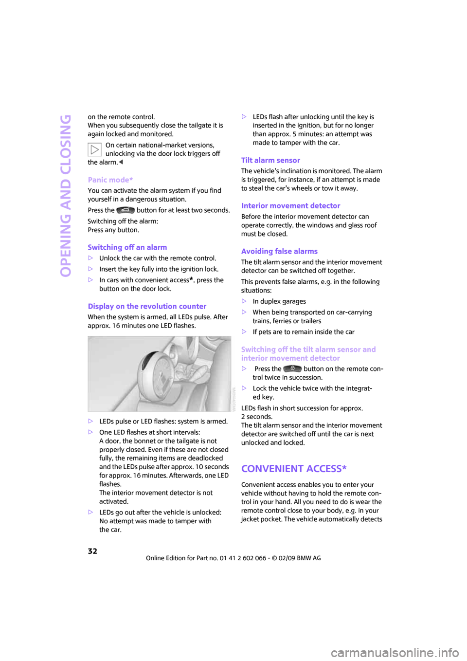
Display on the revolution counter
When the system is armed, all LEDs pulse. After
approx. 16 minutes one LED flashes.
>LEDs pulse or LED flashes: system is armed.
>One LED flashes at short intervals:
A door, the bonnet or the tailgate is not
properly closed. Even if these are not closed
fully, the remaining items are deadlocked
and the LEDs pulse after approx. 10 seconds
for approx. 16 minutes. Afterwards, one LED
flashes.
The interior movement detector is not
activated.
>LEDs go out after the vehicle is unlocked:
No attempt was made to tamper with
the car.>LEDs flash after unlocking until the key is
inserted in the ignition, but for no longer
than approx. 5 minutes: an attempt was
made to tamper with the car.
Tilt alarm sensor
The vehicle's inclination is monitored. The alarm
is triggered, for instance, if an attempt is made
to steal the car's wheels or tow it away.
Interior movement detector
Before the interior movement detector can
operate correctly, the windows and glass roof
must be closed.
Avoiding false alarms
The tilt alarm sensor and the interior movement
detector can be switched off together.
This prevents false alarms, e.g. in the following
situations:
>In duplex garages
>When being transported on car-carrying
trains, ferries or trailers
>If pets are to remain inside the car
Switching off the tilt alarm sensor and
interior movement detector
>Press the button on the remote con-
trol twice in succession.
>Lock the vehicle twice with the integrat-
ed key.
LEDs flash in short succession for approx.
2 seconds.
The tilt alarm sensor and the interior movement
detector are switched off until the car is next
unlocked and locked.
Convenient access*
Convenient access enables you to enter your
vehicle without having to hold the remote con-
trol in your hand. All you need to do is wear the
remote control close to your body, e.g. in your
jacket pocket. The vehicle automatically detects
Page 51 of 218
MOBILITYAT A GLANCE CONTROLS DRIVING TIPS ENTERTAINMENT
49
NAVIGATION REFERENCE
depress the brake until you are ready to
start.<
A lock prevents accidental shifting into selector
lever positions R and P.
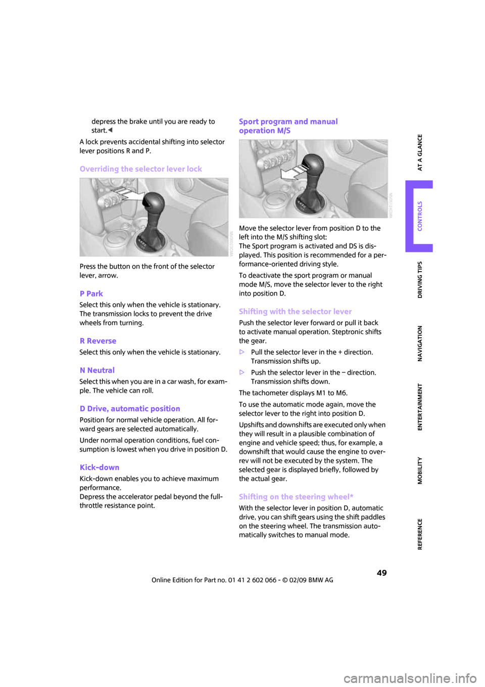
Overriding the selector lever lock
Press the button on the front of the selector
lever, arrow.
P Park
Select this only when the vehicle is stationary.
The transmission locks to prevent the drive
wheels from turning.
R Reverse
Select this only when the vehicle is stationary.
N Neutral
Select this when you are in a car wash, for exam-
ple. The vehicle can roll.
D Drive, automatic position
Position for normal vehicle operation. All for-
ward gears are selected automatically.
Under normal operation conditions, fuel con-
sumption is lowest when you drive in position D.
Kick-down
Kick-down enables you to achieve maximum
performance.
Depress the accelerator pedal beyond the full-
throttle resistance point.
Sport program and manual
operation M/S
Move the selector lever from position D to the
left into the M/S shifting slot:
The Sport program is activated and DS is dis-
played. This position is recommended for a per-
formance-oriented driving style.
To deactivate the sport program or manual
mode M/S, move the selector lever to the right
into position D.
Shifting with the selector lever
Push the selector lever forward or pull it back
to activate manual operation. Steptronic shifts
the gear.
>Pull the selector lever in the + direction.
Transmission shifts up.
>Push the selector lever in the – direction.
Transmission shifts down.
The tachometer displays M1 to M6.
To use the automatic mode again, move the
selector lever to the right into position D.
Upshifts and downshifts are executed only when
they will result in a plausible combination of
engine and vehicle speed; thus, for example, a
downshift that would cause the engine to over-
rev will not be executed by the system. The
selected gear is displayed briefly, followed by
the actual gear.
Shifting on the steering wheel*
With the selector lever in position D, automatic
drive, you can shift gears using the shift paddles
on the steering wheel. The transmission auto-
matically switches to manual mode.
Page 72 of 218
Technology for driving comfort and safety
70
Technology for driving comfort
and safety
Park Distance
Control PDC*
The concept
PDC assists you with parking backwards. Acous-
tic signals and a visual indicator
warn you of the
presence of an object behind the vehicle. To
measure the distance, there are four ultrasonic
sensors in either bumper.
These sensors have a range of approx.
6.5ft/2m. However, an acoustic warning
does not sound until an object is approx. 24 in/
60 cm from the rear corner sensors, or approx.
5 ft/1.50 m from the rear center sensors. PDC is
a parking aid that can indicate objects when
they are approached slowly, as is usually the
case when parking. Avoid approaching an
object at high speed, otherwise physical circum-
stances may lead to the system warning being
issued too late.<
Automatic mode
With the engine running or the ignition switched
on, the system is activated automatically after
approx. 1 second when you engage reverse gear
or move the automatic transmission selector
lever to position R. Wait this short period before
driving.
Acoustic signals
As the distance between vehicle and object
decreases, the intervals between the tones
become shorter. If the distance to the nearest
object falls to below roughly 1 ft/30 cm, then a
continuous tone sounds.
If the distance remains constant, e.g. when driv-
ing parallel to a wall, the acoustic signal stops
after approx. 3 seconds.
Malfunction
Indicator lamp comes on: PDC is mal-
functioning. A message appears on the
Control Display. Have the system
checked.
To avoid this problem, keep the sensors clean
and free of ice or snow in order to ensure that
they will continue to operate effectively. When
using a high-pressure cleaner, do not direct the
jet toward the sensors for lengthy periods and
only spray from a distance of at least 4 in/10 cm.
PDC with visual warning
To have the system show distances to objects on
the Control Display. The contours of distant
objects are shown on the Control Display even
before the acoustic signal sounds.
Onboard monitor, for operating principle refer
to page16.
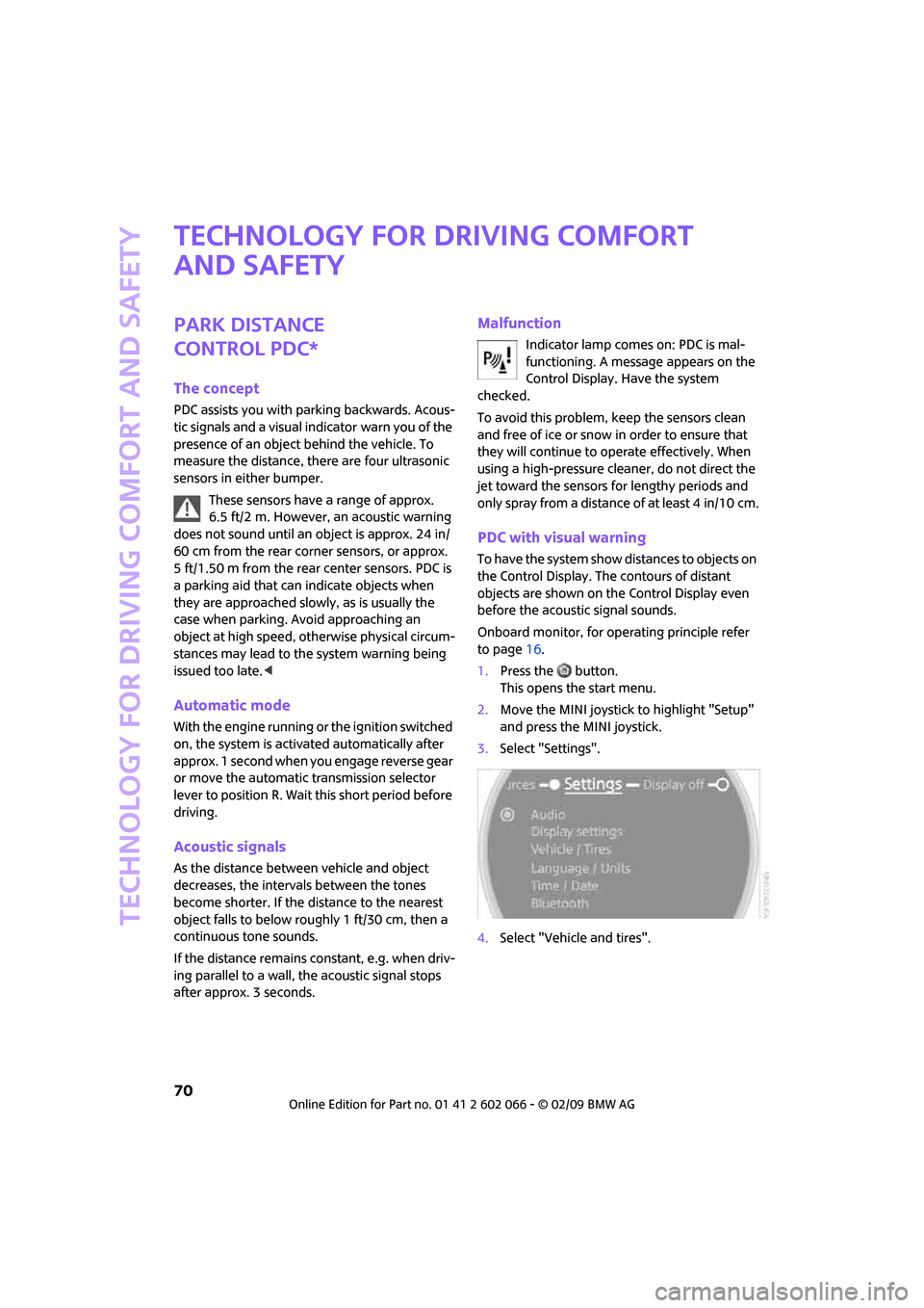
1.Press the button.
This opens the start menu.
2.Move the MINI joystick to highlight "Setup"
and press the MINI joystick.
3.Select "Settings".
4.Select "Vehicle and tires".
Page 98 of 218
Things to remember when driving
96
Things to remember when driving
Break-in period
Moving parts need breaking-in time to adjust to
each other. Please follow the instructions below
in order to achieve the optimal service life and
economy of operation for your vehicle.
Engine and differential
Always obey all official speed limits.
Up to 1,200 miles/2,000 km
Drive at varying engine and road speeds, but do
not exceed the following:
>Gasoline engine
4,500 rpm or 100 mph/160 km/h
Avoid full-throttle operation and use of the
transmission's kick-down mode.
After driving 1,200 miles/2,000 km
Engine and vehicle speeds can be gradually
increased.
Tires
Due to technical factors associated with their
manufacture, tires do not achieve their full trac-
tion potential until after an initial break-in
period. Therefore, drive cautiously during the
first 200 miles/300 km.
Brake system
Brakes require an initial break-in period of
approx. 300 miles/500 km to achieve optimized
contact and wear patterns between brake pads
and rotors. Drive cautiously during this break-in
period.
Clutch
The function of the clutch reaches its optimal
level only after a distance driven of approx.
300 miles/500 km. During this break-in period,
engage the clutch gently.
Following part replacement
The same break-in procedures should be
observed if any of the components mentioned
above have to be renewed in the course of the
vehicle's operating life.
General driving notes
Close splitdoor
Drive the vehicle only when the splitdoor
is closed. Otherwise, exhaust fumes could
penetrate the interior of the vehicle.<
If special circumstances make it absolutely nec-
essary to drive with the splitdoor open:
1.Close all windows and the glass sunroof.
2.Switch off the recirculated-air mode and sig-
nificantly increase the air flow rate of the
automatic climate control, page87.
Hot exhaust system
In all vehicles, extremely high tempera-
tures are generated in the exhaust sys-
tem. Do not remove the heat shields installed
adjacent to various sections of the exhaust sys-
tem, and never apply undercoating to them.
When driving, standing at idle and while park-
ing, take care to avoid possible contact between
the hot exhaust system and any highly flamma-
ble materials such as hay, leaves, grass, etc. Such
contact could lead to a fire, with the risk of seri-
ous personal injuries and property damage. Do
not touch hot exhaust tail pipes. Otherwise
there is a risk of burns.<
Hydroplaning
When driving on wet or slushy roads,
reduce road speed. If you do not, a wedge
of water can form between tires and road sur-
face. This situation, known as hydroplaning, can
cause partial or complete loss of tire contact
with the road surface, so that the car cannot be
steered or braked properly.<
Page 103 of 218
MOBILITYAT A GLANCE CONTROLS DRIVING TIPS ENTERTAINMENT
101
NAVIGATION REFERENCE
sudden swerves, etc., and endanger the occu-
pants. Do not secure cargo using the fastening
points for the tether strap, page44; they may
become damaged.<
Roof-mounted
luggage rack*
A special rack system is available as an option for
your MINI. Your MINI Dealer will be glad to
advise you. Comply with the installation instruc-
tions supplied with the rack system.
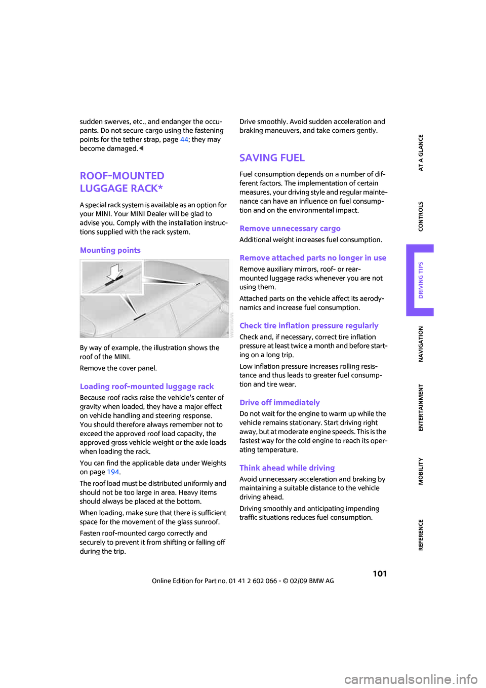
Mounting points
By way of example, the illustration shows the
roof of the MINI.
Remove the cover panel.
Loading roof-mounted luggage rack
Because roof racks raise the vehicle's center of
gravity when loaded, they have a major effect
on vehicle handling and steering response.
You should therefore always remember not to
exceed the approved roof load capacity, the
approved gross vehicle weight or the axle loads
when loading the rack.
You can find the applicable data under Weights
on page194.
The roof load must be distributed uniformly and
should not be too large in area. Heavy items
should always be placed at the bottom.
When loading, make sure that there is sufficient
space for the movement of the glass sunroof.
Fasten roof-mounted cargo correctly and
securely to prevent it from shifting or falling off
during the trip.Drive smoothly. Avoid sudden acceleration and
braking maneuvers, and take corners gently.
Saving fuel
Fuel consumption depends on a number of dif-
ferent factors. The implementation of certain
measures, your driving style and regular mainte-
nance can have an influence on fuel consump-
tion and on the environmental impact.
Remove unnecessary cargo
Additional weight increases fuel consumption.
Remove attached parts no longer in use
Remove auxiliary mirrors, roof- or rear-
mounted luggage racks whenever you are not
using them.
Attached parts on the vehicle affect its aerody-
namics and increase fuel consumption.
Check tire inflation pressure regularly
Check and, if necessary, correct tire inflation
pressure at least twice a month and before start-
ing on a long trip.
Low inflation pressure increases rolling resis-
tance and thus leads to greater fuel consump-
tion and tire wear.
Drive off immediately
Do not wait for the engine to warm up while the
vehicle remains stationary. Start driving right
away, but at moderate engine speeds. This is the
fastest way for the cold engine to reach its oper-
ating temperature.
Think ahead while driving
Avoid unnecessary acceleration and braking by
maintaining a suitable distance to the vehicle
driving ahead.
Driving smoothly and anticipating impending
traffic situations reduces fuel consumption.
Page 166 of 218
Wheels and tires
164
Run-Flat Tires*
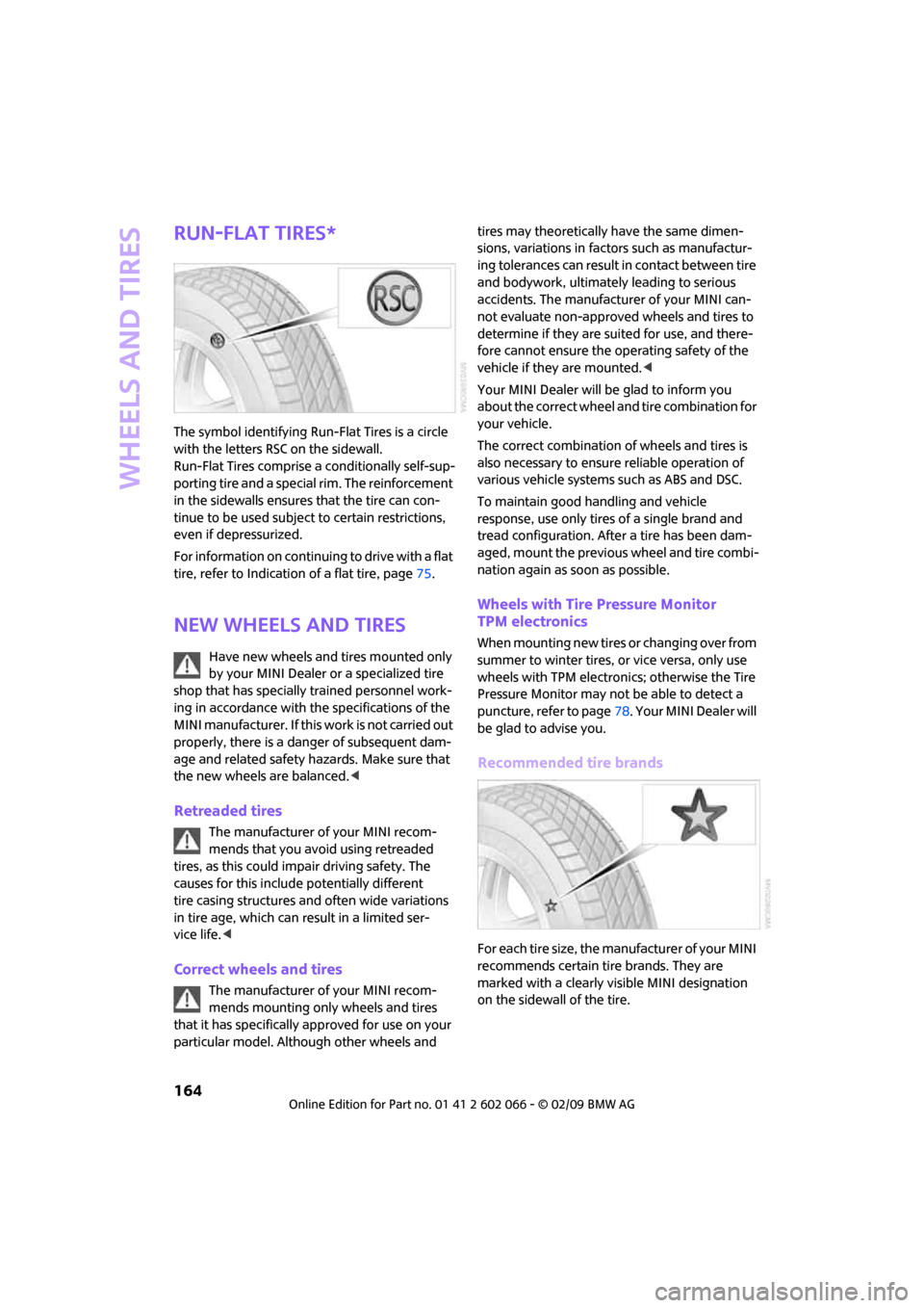
The symbol identifying Run-Flat Tires is a circle
with the letters RSC on the sidewall.
Run-Flat Tires comprise a conditionally self-sup-
porting tire and a special rim. The reinforcement
in the sidewalls ensures that the tire can con-
tinue to be used subject to certain restrictions,
even if depressurized.
For information on continuing to drive with a flat
tire, refer to Indication of a flat tire, page75.
New wheels and tires
Have new wheels and tires mounted only
by your MINI Dealer or a specialized tire
shop that has specially trained personnel work-
ing in accordance with the specifications of the
MINI manufacturer. If this work is not carried out
properly, there is a danger of subsequent dam-
age and related safety hazards. Make sure that
the new wheels are balanced.<
Retreaded tires
The manufacturer of your MINI recom-
mends that you avoid using retreaded
tires, as this could impair driving safety. The
causes for this include potentially different
tire casing structures and often wide variations
in tire age, which can result in a limited ser-
vice life.<
Correct wheels and tires
The manufacturer of your MINI recom-
mends mounting only wheels and tires
that it has specifically approved for use on your
particular model. Although other wheels and tires may theoretically have the same dimen-
sions, variations in factors such as manufactur-
ing tolerances can result in contact between tire
and bodywork, ultimately leading to serious
accidents. The manufacturer of your MINI can-
not evaluate non-approved wheels and tires to
determine if they are suited for use, and there-
fore cannot ensure the operating safety of the
vehicle if they are mounted.<
Your MINI Dealer will be glad to inform you
about the correct wheel and tire combination for
your vehicle.
The correct combination of wheels and tires is
also necessary to ensure reliable operation of
various vehicle systems such as ABS and DSC.
To maintain good handling and vehicle
response, use only tires of a single brand and
tread configuration. After a tire has been dam-
aged, mount the previous wheel and tire combi-
nation again as soon as possible.
Wheels with Tire Pressure Monitor
TPM electronics
When mounting new tires or changing over from
summer to winter tires, or vice versa, only use
wheels with TPM electronics; otherwise the Tire
Pressure Monitor may not be able to detect a
puncture, refer to page78. Your MINI Dealer will
be glad to advise you.
Recommended tire brands
For each tire size, the manufacturer of your MINI
recommends certain tire brands. They are
marked with a clearly visible MINI designation
on the sidewall of the tire.
Page 172 of 218
Maintenance
170
Maintenance
MINI Maintenance System
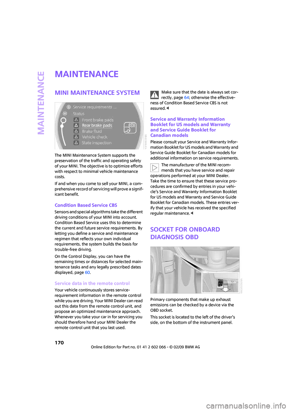
The MINI Maintenance System supports the
preservation of the traffic and operating safety
of your MINI. The objective is to optimize efforts
with respect to minimal vehicle maintenance
costs.
If and when you come to sell your MINI, a com-
prehensive record of servicing will prove a signif-
icant benefit.
Condition Based Service CBS
Sensors and special algorithms take the different
driving conditions of your MINI into account.
Condition Based Service uses this to determine
the current and future service requirements. By
letting you define a service and maintenance
regimen that reflects your own individual
requirements, the system builds the basis for
trouble-free driving.
On the Control Display, you can have the
remaining times or distances for selected main-
tenance tasks and any legally prescribed dates
displayed, page60.
Service data in the remote control
Your vehicle continuously stores service-
requirement information in the remote control
while you are driving. Your MINI Dealer can read
out this data from the remote control unit, and
propose an optimized maintenance approach.
Whenever you take your car in for servicing you
should therefore hand your MINI Dealer the
remote control unit that you last used.Make sure that the date is always set cor-
rectly, page64; otherwise the effective-
ness of Condition Based Service CBS is not
assured.<
Service and Warranty Information
Booklet for US models and Warranty
and Service Guide Booklet for
Canadian models
Please consult your Service and Warranty Infor-
mation Booklet for US models and Warranty and
Service Guide Booklet for Canadian models for
additional information on service requirements.
The manufacturer of the MINI recom-
mends that you have service and repair
operations performed at your MINI Dealer.
Take the time to ensure that these service pro-
cedures are confirmed by entries in your vehi-
cle's Service and Warranty Information Booklet
for US models and Warranty and Service Guide
Booklet for Canadian models. These entries ver-
ify that your vehicle has received the specified
regular maintenance.<
Socket for Onboard
Diagnosis OBD
Primary components that make up exhaust
emissions can be checked by a device via the
OBD socket.
This socket is located to the left of the driver's
side, on the bottom of the instrument panel.
Page 173 of 218
MOBILITYAT A GLANCE CONTROLS DRIVING TIPS ENTERTAINMENT
171
NAVIGATION REFERENCE
Exhaust emission values
The warning lamps come on. The
exhaust emission values have turned
poor and there is a danger of engine
damage. You can continue your jour-
ney, but moderate your speed and exercise
due caution. Have the car checked as soon as
possible.
Under certain circumstances, one of the lamps
will flash or light up continuously. This indicates
excessive misfiring or a malfunction in the
engine. If this happens, reduce your speed and
visit the nearest MINI Dealer as soon as possible.
Severe misfiring can quickly lead to serious dam-
age of emissions-related components, espe-
cially the catalytic converter. In addition,
mechanical engine components can become
damaged.
If the fuel filler cap is not properly tightened, the
OBD system may conclude that fuel vapors are
escaping, causing an indicator to light up. If the
filler cap is then tightened, the indicator should
go out within a few days.
Event data recorders
Your vehicle may be equipped with one or sev-
eral measuring or diagnostic modules or a
device for recording or sending certain vehicle
data or information.