tow MINI Clubman 2009 Owner's Manual (Mini Connected)
[x] Cancel search | Manufacturer: MINI, Model Year: 2009, Model line: Clubman, Model: MINI Clubman 2009Pages: 218, PDF Size: 3.69 MB
Page 8 of 218
Notes
6
>Federal Emissions System Defect Warranty
>Federal Emissions Performance Warranty
>California Emission Control System Limited
Warranty
Detailed information about these warranties is
listed in the Service and Warranty Information
Booklet for US models or in the Warranty and
Service Guide Booklet for Canadian models.
Your vehicle has been specifically adapted and
designed to meet the particular operating con-
ditions and homologation requirements in your
country and continental region in order to
deliver the full driving pleasure while the vehicle
is operated under those conditions. If you wish
to operate your vehicle in another country or
region, you may be required to adapt your vehi-
cle to meet different prevailing operating condi-
tions and homologation requirements. You
should also be aware of any applicable warranty
limitations or exclusions for such country or
region. In such case, please contact Customer
Relations for further information.
Reporting safety defects
For US customers
The following applies only to vehicles owned
and operated in the US.
If you believe that your vehicle has a defect
which could cause a crash or could cause injury
or death, you should immediately inform the
National Highway Traffic Safety Administration,
NHTSA, in addition to notifying MINI of North
America, LLC, P.O. Box 1227, Westwood,
New Jersey 07675-1227,
Telephone 1-800-831-1117.
If NHTSA receives similar complaints, it may
open an investigation, and if it finds that a safety
defect exists in a group of vehicles, it may order
a recall and remedy campaign. However, NHTSA
cannot become involved in individual problems
between you, your dealer, or MINI of North
America, LLC.
To contact NHTSA, you may call the Vehicle
Safety Hotline toll-free at 1-888-327-4236 (TTY: 1-800-424-9153);
go to http://www.safercar.gov; or write to:
Administrator, NHTSA, 400 Seventh Street, SW.,
Washington, DC 20590. You can also obtain
other information about motor vehicle safety
from http://www.safercar.gov
For Canadian customers
Canadian customers who wish to report a
safety-related defect to Transport Canada,
Defect Investigations and Recalls, may call
1-800-333-0510 toll-free from anywhere in
Canada or 1-613-993-9851 from the Ottawa
region and from other countries, or contact
Transport Canada by mail at: Transport Canada,
ASFAD, Place de Ville, Tower C, 330 Sparks
Street, Ottawa, ON, K1A 0N5.
You can also obtain other information about
motor vehicle safety from http://www.tc.gc.ca
Page 33 of 218
MOBILITYAT A GLANCE CONTROLS DRIVING TIPS ENTERTAINMENT
31
NAVIGATION REFERENCE
Clubdoor
Opening
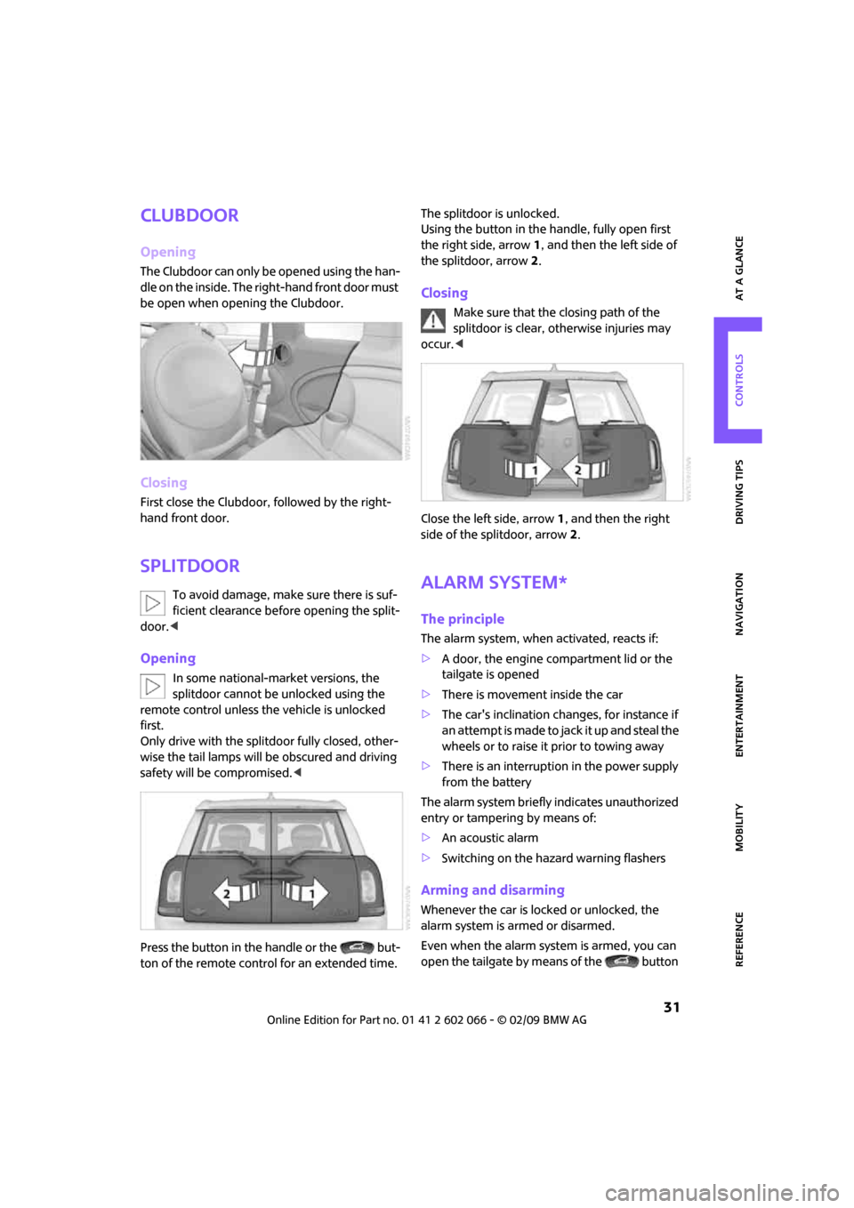
The Clubdoor can only be opened using the han-
dle on the inside. The right-hand front door must
be open when opening the Clubdoor.
Closing
First close the Clubdoor, followed by the right-
hand front door.
Splitdoor
To avoid damage, make sure there is suf-
ficient clearance before opening the split-
door.<
Opening
In some national-market versions, the
splitdoor cannot be unlocked using the
remote control unless the vehicle is unlocked
first.
Only drive with the splitdoor fully closed, other-
wise the tail lamps will be obscured and driving
safety will be compromised.<
Press the button in the handle or the but-
ton of the remote control for an extended time. The splitdoor is unlocked.
Using the button in the handle, fully open first
the right side, arrow1, and then the left side of
the splitdoor, arrow2.
Closing
Make sure that the closing path of the
splitdoor is clear, otherwise injuries may
occur.<
Close the left side, arrow1, and then the right
side of the splitdoor, arrow2.
Alarm system*
The principle
The alarm system, when activated, reacts if:
>A door, the engine compartment lid or the
tailgate is opened
>There is movement inside the car
>The car's inclination changes, for instance if
an attempt is made to jack it up and steal the
wheels or to raise it prior to towing away
>There is an interruption in the power supply
from the battery
The alarm system briefly indicates unauthorized
entry or tampering by means of:
>An acoustic alarm
>Switching on the hazard warning flashers
Arming and disarming
Whenever the car is locked or unlocked, the
alarm system is armed or disarmed.
Even when the alarm system is armed, you can
open the tailgate by means of the button
Page 34 of 218
Opening and closing
32
on the remote control.
When you subsequently close the tailgate it is
again locked and monitored.
On certain national-market versions,
unlocking via the door lock triggers off
the alarm.<
Panic mode*
You can activate the alarm system if you find
yourself in a dangerous situation.
Press the button for at least two seconds.
Switching off the alarm:
Press any button.
Switching off an alarm
>Unlock the car with the remote control.
>Insert the key fully into the ignition lock.
>In cars with convenient access
*, press the
button on the door lock.
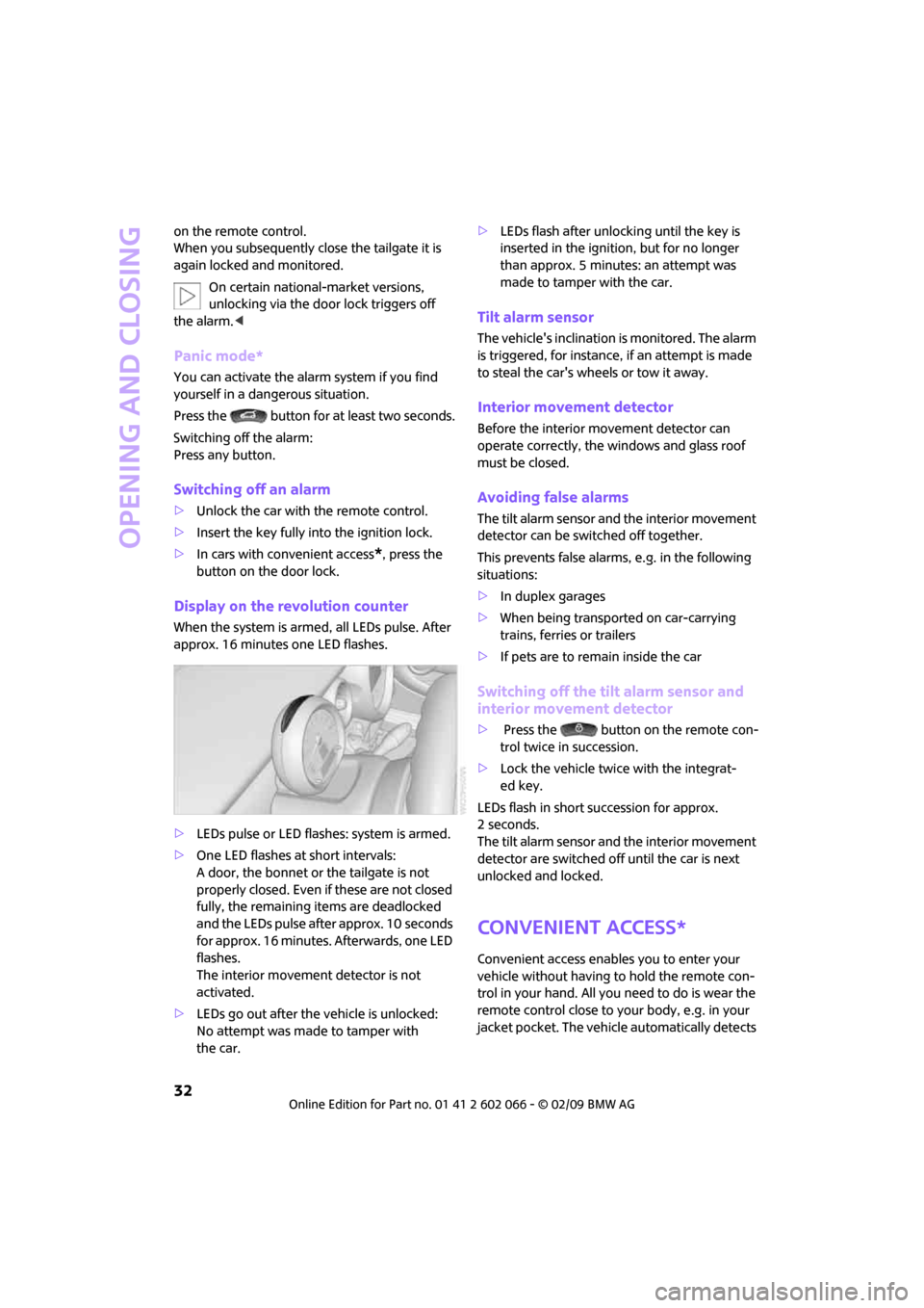
Display on the revolution counter
When the system is armed, all LEDs pulse. After
approx. 16 minutes one LED flashes.
>LEDs pulse or LED flashes: system is armed.
>One LED flashes at short intervals:
A door, the bonnet or the tailgate is not
properly closed. Even if these are not closed
fully, the remaining items are deadlocked
and the LEDs pulse after approx. 10 seconds
for approx. 16 minutes. Afterwards, one LED
flashes.
The interior movement detector is not
activated.
>LEDs go out after the vehicle is unlocked:
No attempt was made to tamper with
the car.>LEDs flash after unlocking until the key is
inserted in the ignition, but for no longer
than approx. 5 minutes: an attempt was
made to tamper with the car.
Tilt alarm sensor
The vehicle's inclination is monitored. The alarm
is triggered, for instance, if an attempt is made
to steal the car's wheels or tow it away.
Interior movement detector
Before the interior movement detector can
operate correctly, the windows and glass roof
must be closed.
Avoiding false alarms
The tilt alarm sensor and the interior movement
detector can be switched off together.
This prevents false alarms, e.g. in the following
situations:
>In duplex garages
>When being transported on car-carrying
trains, ferries or trailers
>If pets are to remain inside the car
Switching off the tilt alarm sensor and
interior movement detector
>Press the button on the remote con-
trol twice in succession.
>Lock the vehicle twice with the integrat-
ed key.
LEDs flash in short succession for approx.
2 seconds.
The tilt alarm sensor and the interior movement
detector are switched off until the car is next
unlocked and locked.
Convenient access*
Convenient access enables you to enter your
vehicle without having to hold the remote con-
trol in your hand. All you need to do is wear the
remote control close to your body, e.g. in your
jacket pocket. The vehicle automatically detects
Page 52 of 218
Driving
50
If you do not shift gears with the shift paddles or
accelerate for a certain amount of time, the
transmission automatically returns to D, auto-
matic drive.
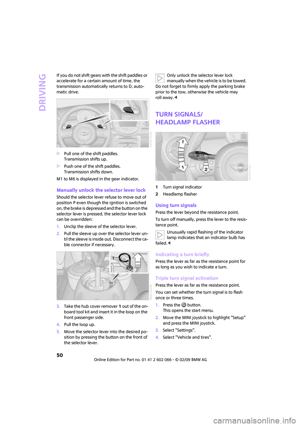
>Pull one of the shift paddles.
Transmission shifts up.
>Push one of the shift paddles.
Transmission shifts down.
M1 to M6 is displayed in the gear indicator.
Manually unlock the selector lever lock
Should the selector lever refuse to move out of
position P even though the ignition is switched
on, the brake is depressed and the button on the
selector lever is pressed, the selector lever lock
can be overridden:
1.Unclip the sleeve of the selector lever.
2.Pull the sleeve up over the selector lever un-
til the sleeve is inside out. Disconnect the ca-
ble connector if necessary.
3.Take the hub cover remover1 out of the on-
board tool kit and insert it in the loop on the
front passenger side.
4.Pull the loop up.
5.Move the selector lever into the desired po-
sition by pressing the button on the front of
the selector lever.Only unlock the selector lever lock
manually when the vehicle is to be towed.
Do not forget to firmly apply the parking brake
prior to the tow, otherwise the vehicle may
roll away.<
Turn signals/
headlamp flasher
1Turn signal indicator
2Headlamp flasher
Using turn signals
Press the lever beyond the resistance point.
To turn off manually, press the lever to the resis-
tance point.
Unusually rapid flashing of the indicator
lamp indicates that an indicator bulb has
failed.<
Indicating a turn briefly
Press the lever as far as the resistance point for
as long as you wish to indicate a turn.
Triple turn signal activation
Press the lever as far as the resistance point.
You can set whether the turn signal is to flash
once or three times.
1.Press the button.
This opens the start menu.
2.Move the MINI joystick to highlight "Setup"
and press the MINI joystick.
3.Select "Settings".
4.Select "Vehicle and tires".
Page 72 of 218
Technology for driving comfort and safety
70
Technology for driving comfort
and safety
Park Distance
Control PDC*
The concept
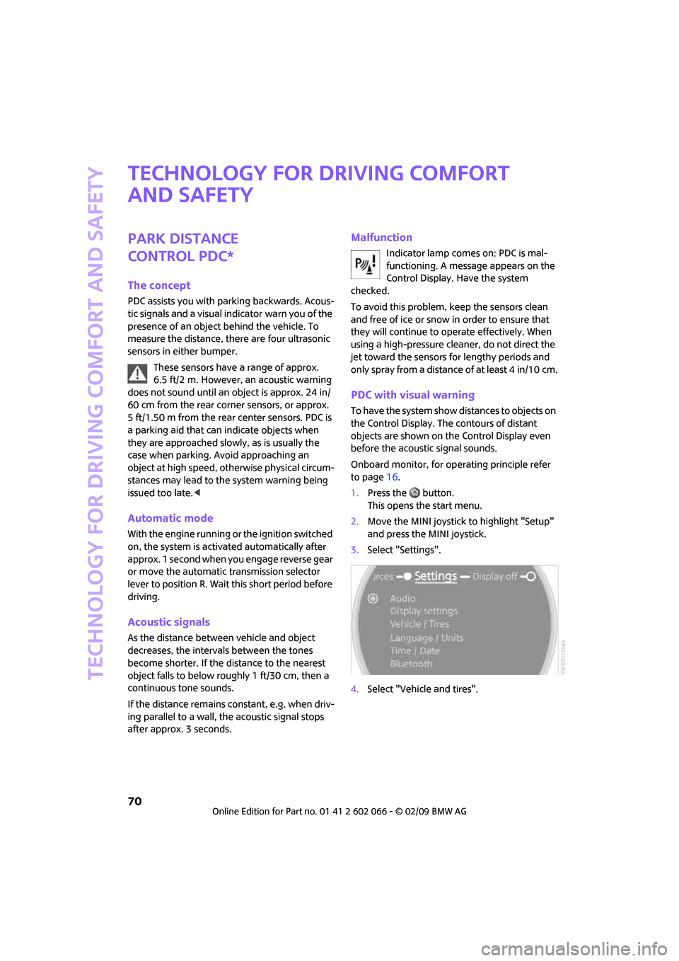
PDC assists you with parking backwards. Acous-
tic signals and a visual indicator
warn you of the
presence of an object behind the vehicle. To
measure the distance, there are four ultrasonic
sensors in either bumper.
These sensors have a range of approx.
6.5ft/2m. However, an acoustic warning
does not sound until an object is approx. 24 in/
60 cm from the rear corner sensors, or approx.
5 ft/1.50 m from the rear center sensors. PDC is
a parking aid that can indicate objects when
they are approached slowly, as is usually the
case when parking. Avoid approaching an
object at high speed, otherwise physical circum-
stances may lead to the system warning being
issued too late.<
Automatic mode
With the engine running or the ignition switched
on, the system is activated automatically after
approx. 1 second when you engage reverse gear
or move the automatic transmission selector
lever to position R. Wait this short period before
driving.
Acoustic signals
As the distance between vehicle and object
decreases, the intervals between the tones
become shorter. If the distance to the nearest
object falls to below roughly 1 ft/30 cm, then a
continuous tone sounds.
If the distance remains constant, e.g. when driv-
ing parallel to a wall, the acoustic signal stops
after approx. 3 seconds.
Malfunction
Indicator lamp comes on: PDC is mal-
functioning. A message appears on the
Control Display. Have the system
checked.
To avoid this problem, keep the sensors clean
and free of ice or snow in order to ensure that
they will continue to operate effectively. When
using a high-pressure cleaner, do not direct the
jet toward the sensors for lengthy periods and
only spray from a distance of at least 4 in/10 cm.
PDC with visual warning
To have the system show distances to objects on
the Control Display. The contours of distant
objects are shown on the Control Display even
before the acoustic signal sounds.
Onboard monitor, for operating principle refer
to page16.
1.Press the button.
This opens the start menu.
2.Move the MINI joystick to highlight "Setup"
and press the MINI joystick.
3.Select "Settings".
4.Select "Vehicle and tires".
Page 73 of 218
MOBILITYAT A GLANCE CONTROLS DRIVING TIPS ENTERTAINMENT
71
NAVIGATION REFERENCE
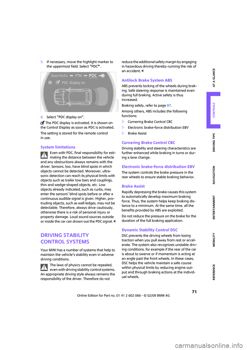
5.If necessary, move the highlight marker to
the uppermost field. Select "PDC" .
6.Select "PDC display on".
The PDC display is activated. It is shown on
the Control Display as soon as PDC is activated.
The setting is stored for the remote control
in use.
System limitations
Even with PDC, final responsibility for esti-
mating the distance between the vehicle
and any obstructions always remains with the
driver. Sensors, too, have blind spots in which
objects cannot be detected. Moreover, ultra-
sonic detection can reach its physical limits with
objects such as trailer tow bars and couplings,
thin and wedge-shaped objects, etc. Low
objects already indicated, such as curbs, may
enter the sensors' blind spots before or after a
continuous audible signal is given. Higher, pro-
truding objects, such as wall ledges, may not be
detectable. Therefore, always drive cautiously,
otherwise there is a risk of personal injury or
property damage. Loud sound sources outside
or inside the car can drown out the PDC signal.<
Driving stability
control systems
Your MINI has a number of systems that help to
maintain the vehicle's stability even in adverse
driving conditions.
The laws of physics cannot be repealed,
even with driving stability control systems.
An appropriate driving style always remains the
responsibility of the driver. Therefore do not reduce the additional safety margin by engaging
in hazardous driving thereby running the risk of
an accident.<
Antilock Brake System ABS
ABS prevents locking of the wheels during brak-
ing. Safe steering response is maintained even
during full braking. Active safety is thus
increased.
Braking safely, refer to page97.
Among others, ABS includes the following
functions:
>Cornering Brake Control CBC
>Electronic brake-force distribution EBV
>Brake Assist
Cornering Brake Control CBC
Driving stability and steering characteristics are
further enhanced while braking in turns or dur-
ing a lane change.
Electronic brake-force distribution EBV
The system controls the brake pressure in the
rear wheels to ensure stable braking behavior.
Brake Assist
Rapidly depressing the brake causes this system
to automatically develop maximum braking
force. Thus, the system helps keep braking dis-
tance to a minimum. At the same time, all the
benefits provided by ABS are exploited.
Do not reduce the pressure on the brake for the
duration of the full braking application.
Dynamic Stability Control DSC
DSC prevents the driving wheels from losing
traction when you pull away from rest or accel-
erate. The system also recognizes unstable driv-
ing conditions, for example if the rear of the car
is about to swerve or if momentum is acting at
an angle past the front wheels. In these cases,
DSC helps the vehicle maintain a safe course
within physical limits by reducing engine out-
put and through braking actions at the individ-
ual wheels.
Page 87 of 218
MOBILITYAT A GLANCE CONTROLS DRIVING TIPS ENTERTAINMENT
85
NAVIGATION REFERENCE
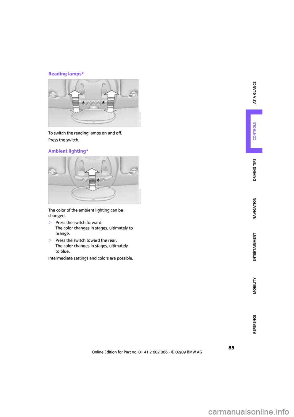
Reading lamps*
To switch the reading lamps on and off.
Press the switch.
Ambient lighting*
The color of the ambient lighting can be
changed.
>Press the switch forward.
The color changes in stages, ultimately to
orange.
>Press the switch toward the rear.
The color changes in stages, ultimately
to blue.
Intermediate settings and colors are possible.
Page 88 of 218
Climate
86
Climate
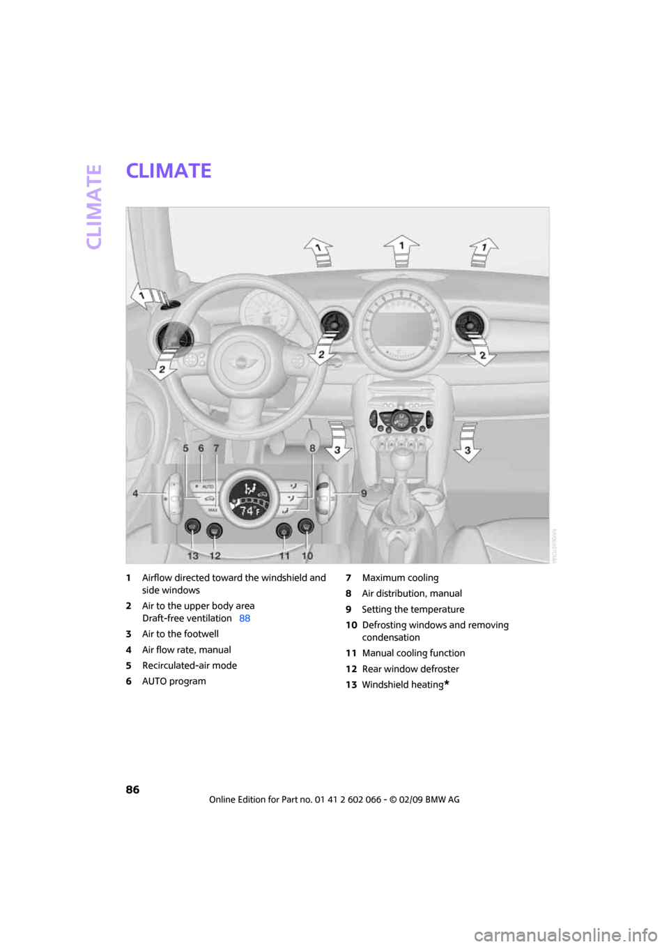
1Airflow directed toward the windshield and
side windows
2Air to the upper body area
Draft-free ventilation88
3Air to the footwell
4Air flow rate, manual
5Recirculated-air mode
6AUTO program7Maximum cooling
8Air distribution, manual
9Setting the temperature
10Defrosting windows and removing
condensation
11Manual cooling function
12Rear window defroster
13Windshield heating
*
Page 89 of 218
MOBILITYAT A GLANCE CONTROLS DRIVING TIPS ENTERTAINMENT
87
NAVIGATION REFERENCE
Automatic climate
control
Comfortable interior climate
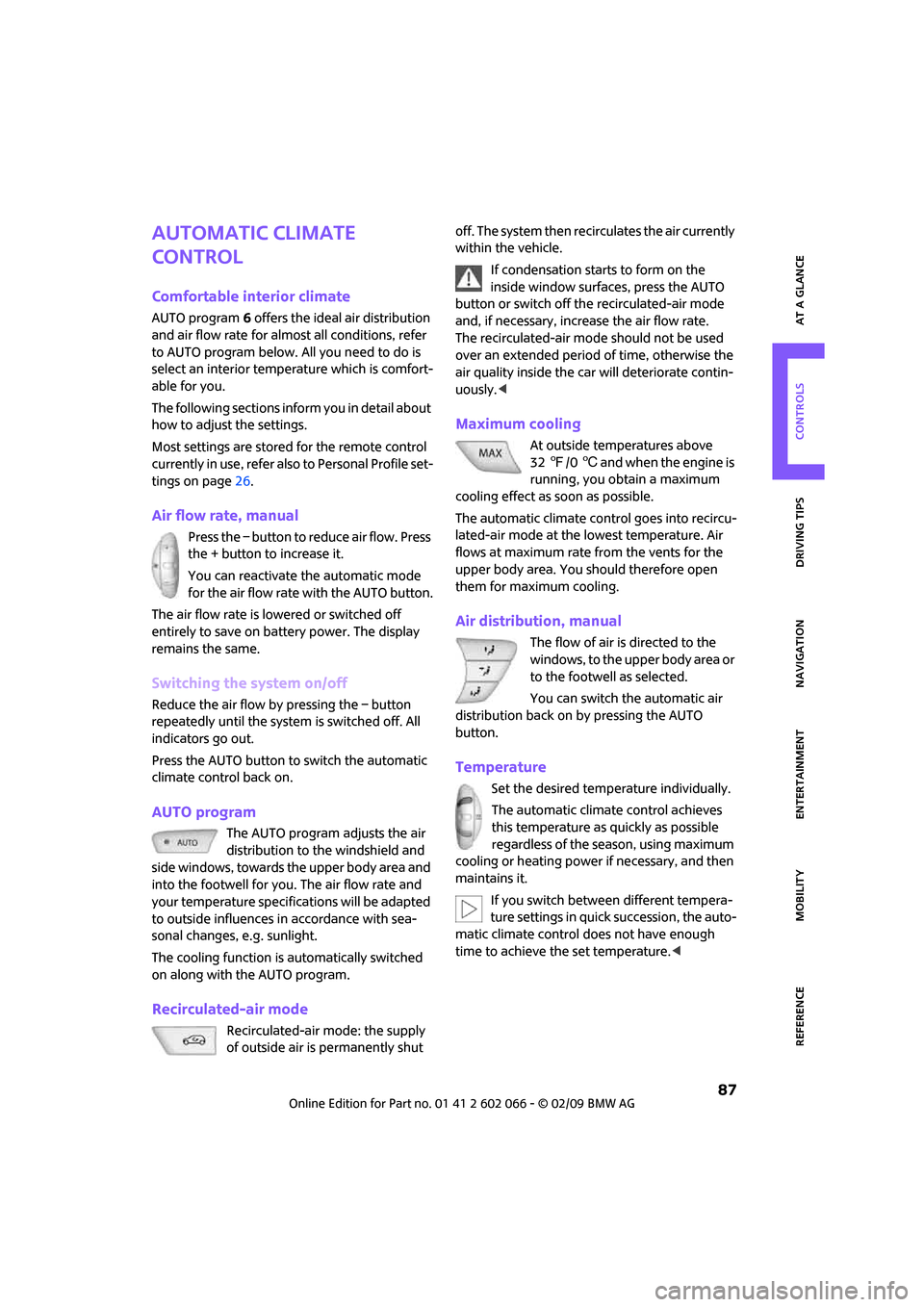
AUTO program6 offers the ideal air distribution
and air flow rate for almost all conditions, refer
to AUTO program below. All you need to do is
select an interior temperature which is comfort-
able for you.
The following sections inform you in detail about
how to adjust the settings.
Most settings are stored for the remote control
currently in use, refer also to Personal Profile set-
tings on page26.
Air flow rate, manual
Press the – button to reduce air flow. Press
the + button to increase it.
You can reactivate the automatic mode
for the air flow rate with the AUTO button.
The air flow rate is lowered or switched off
entirely to save on battery power. The display
remains the same.
Switching the system on/off
Reduce the air flow by pressing the – button
repeatedly until the system is switched off. All
indicators go out.
Press the AUTO button to switch the automatic
climate control back on.
AUTO program
The AUTO program adjusts the air
distribution to the windshield and
side windows, towards the upper body area and
into the footwell for you. The air flow rate and
your temperature specifications will be adapted
to outside influences in accordance with sea-
sonal changes, e.g. sunlight.
The cooling function is automatically switched
on along with the AUTO program.
Recirculated-air mode
Recirculated-air mode: the supply
of outside air is permanently shut off. The system then recirculates the air currently
within the vehicle.
If condensation starts to form on the
inside window surfaces, press the AUTO
button or switch off the recirculated-air mode
and, if necessary, increase the air flow rate.
The recirculated-air mode should not be used
over an extended period of time, otherwise the
air quality inside the car will deteriorate contin-
uously.<
Maximum cooling
At outside temperatures above
327/06 and when the engine is
running, you obtain a maximum
cooling effect as soon as possible.
The automatic climate control goes into recircu-
lated-air mode at the lowest temperature. Air
flows at maximum rate from the vents for the
upper body area. You should therefore open
them for maximum cooling.
Air distribution, manual
The flow of air is directed to the
windows, to the upper body area or
to the footwell as selected.
You can switch the automatic air
distribution back on by pressing the AUTO
button.
Temperature
Set the desired temperature individually.
The automatic climate control achieves
this temperature as quickly as possible
regardless of the season, using maximum
cooling or heating power if necessary, and then
maintains it.
If you switch between different tempera-
ture settings in quick succession, the auto-
matic climate control does not have enough
time to achieve the set temperature.<
Page 101 of 218
MOBILITYAT A GLANCE CONTROLS DRIVING TIPS ENTERTAINMENT
99
NAVIGATION REFERENCE
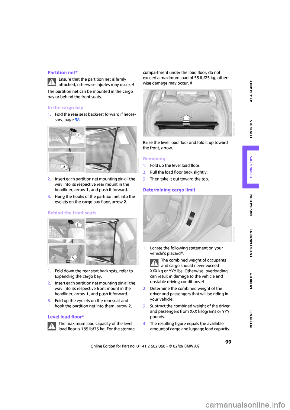
Partition net*
Ensure that the partition net is firmly
attached, otherwise injuries may occur.<
The partition net can be mounted in the cargo
bay or behind the front seats.
In the cargo bay
1.Fold the rear seat backrest forward if neces-
sary, page98.
2.Insert each partition net mounting pin all the
way into its respective rear mount in the
headliner, arrow 1, and push it forward.
3.Hang the hooks of the partition net into the
eyelets on the cargo bay floor, arrow2.
Behind the front seats
1.Fold down the rear seat backrests, refer to
Expanding the cargo bay.
2.Insert each partition net mounting pin all the
way into its respective front mount in the
headliner, arrow1, and push it forward.
3.Fold up the eyelets on the rear seat and
hook the partition net into them, arrow2.
Level load floor*
The maximum load capacity of the level
load floor is 165 lb/75 kg. For the storage compartment under the load floor, do not
exceed a maximum load of 55 lb/25 kg, other-
wise damage may occur.<
Raise the level load floor and fold it up toward
the front, arrow.
Removing
1.Fold up the level load floor.
2.Pull the load floor back slightly.
3.Then take it out toward the top.
Determining cargo limit
1.Locate the following statement on your
vehicle's placard
*:
The combined weight of occupants
and cargo should never exceed
XXX kg or YYY lbs. Otherwise, overloading
can result in damage to the vehicle and
unstable driving conditions.<
2.Determine the combined weight of the
driver and passengers that will be riding in
your vehicle.
3.Subtract the combined weight of the driver
and passengers from XXX kilograms or YYY
pounds.
4.The resulting figure equals the available
amount of cargo and luggage load capacity.