clock MINI Clubman 2010 Owner's Manual (Mini Connected)
[x] Cancel search | Manufacturer: MINI, Model Year: 2010, Model line: Clubman, Model: MINI Clubman 2010Pages: 218, PDF Size: 3.97 MB
Page 14 of 218
Cockpit
12
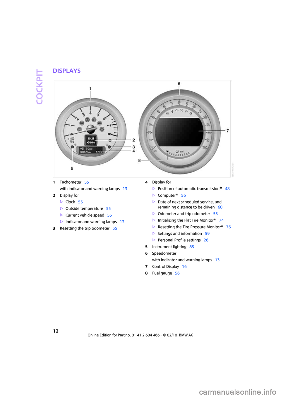
Displays
1Tachometer55
with indicator and warning lamps13
2Display for
>Clock55
>Outside temperature55
>Current vehicle speed55
>Indicator and warning lamps13
3Resetting the trip odometer554Display for
>Position of automatic transmission
*48
>Computer
*56
>Date of next scheduled service, and
remaining distance to be driven60
>Odometer and trip odometer55
>Initializing the Flat Tire Monitor
*74
>Resetting the Tire Pressure Monitor
*76
>Settings and information59
>Personal Profile settings26
5Instrument lighting83
6Speedometer
with indicator and warning lamps13
7Control Display16
8Fuel gauge56
Page 29 of 218
MOBILITYAT A GLANCE CONTROLS DRIVING TIPS ENTERTAINMENT
27
NAVIGATION REFERENCE
>Settings for the displays on the onboard
monitor, in the speedometer and in the
tachometer:
>12h/24h mode of the clock64
>Date format65
>Brightness of the Control Display69
>Language on the Control Display68
>Units of measure for fuel consumption,
distance covered/remaining distances
and temperature60
>Show visual warning for Park Distance Con-
trol PDC
*70
>Light settings:
>Pathway lighting81
>Daytime running lights82
>Automatic climate control: activating/deac-
tivating the AUTO program, setting the tem-
perature, air volume and air distribution86
>Entertainment:
>Audio volume133
>Tone control133
>Speed-dependent volume control133
Central locking system
The concept
The central locking system is ready for operation
whenever the driver's door is closed.
The system simultaneously engages and
releases the locks on the following:
>Doors
>Splitdoor
>Fuel filler flap
Operating from outside
>Via the remote control
>Via the door lock
*
>In cars with Comfort Access*, via the door
handles on the driver's and passenger's
sides.The anti-theft system is also operated at the
same time. It prevents the doors from being
unlocked using the lock buttons or door han-
dles. The remote control can also be used to
switch on/off the welcome lamps and interior
lamps. The alarm system
* is also activated or
deactivated, page31.
Operating from inside
Button for central locking system, page30.
In the event of a sufficiently severe accident, the
central locking system unlocks automatically. In
addition, the hazard warning flashers and inte-
rior lamps come on.
Opening and closing:
from outside
Persons or animals in a parked vehicle
could lock the doors from the inside. Take
the key with you when you leave the vehicle so
that the vehicle can be opened from the out-
side.<
Using the remote control
Unlocking
Press the button.
The welcome lamps and interior lamps come on.
Unlocking mode
You can also set which parts of the car are
unlocked. The setting is stored for the remote
control in use.
Onboard monitor, for operating principle refer
to page16.
1.Press the button.
This opens the start menu.
2.Move the MINI joystick to highlight "Setup"
and press the MINI joystick.
Page 39 of 218
MOBILITYAT A GLANCE CONTROLS DRIVING TIPS ENTERTAINMENT
37
NAVIGATION REFERENCE
Adjustments
Sitting safely
The ideal sitting position can make a vital contri-
bution to relaxed, fatigue-free driving. In con-
junction with the safety belts, the head restraints
and the airbags, the seated position has a major
influence on your safety in the event of an acci-
dent. To ensure that the safety systems operate
with optimal efficiency, we strongly urge you to
observe the instructions contained in the follow-
ing section.
For additional information on transporting chil-
dren safely, refer to page43.
Airbags
Always maintain an adequate distance
between yourself and the airbags. Always
grip the steering wheel on the rim, with your
hands in the 3 o'clock and 9 o'clock positions, to
minimize the risk of injury to the hands or arms
in the event of the airbag being triggered off.
No one and nothing should come between the
airbags and the seat occupant.
Do not use the cover of the front airbag on the
front passenger side as a storage area. Ensure
that the front passenger is correctly seated, e.g.
that no feet or legs are propped against the
dashboard. Otherwise, leg injury could result if
the front airbag suddenly deployed.
Make sure that occupants keep their heads
away from the side airbag and do not lean
against the head-level airbag; otherwise injuries
can occur when the airbag is triggered.<
Even if you follow all the instructions, injuries
resulting from contact with airbags cannot be
fully excluded, depending on the circumstances.
The ignition and inflation noise may provoke a
mild hearing loss in extremely sensitive individ-
uals. This effect is usually only temporary.
For airbag locations and additional information
on airbags, refer to page79.
Head restraint
A correctly adjusted head restraint reduces the
risk of neck injury in the event of an accident.
Adjust the head restraint in such a way
that its center is at approx. ear level. Oth-
erwise, there is an increased risk of injury in the
event of an accident.<
Head restraints, refer to page39.
Safety belt
Before every drive, make sure that all occupants
wear their safety belts. Airbags complement the
safety belt as an additional safety device, but
they do not represent a substitute.
Number of safety belts
Never allow more than one person to
wear a single safety belt. Never allow
infants or small children to ride in a passenger's
lap.
Make sure that the belt in the lap area sits low
across the hips and does not press against the
abdomen. The safety belt must not rest against
the throat, run across sharp edges, pass over
hard or fragile objects or be pinched. Fasten the
safety belt so that it is pulled taut across the lap
and shoulder, fitting the body snugly without
any twists. Otherwise, the belt could slide over
the hips in the event of a frontal collision and
injure the abdomen. Avoid wearing bulky cloth-
ing and regularly pull the belt in the upper-body
area taut; otherwise, its restraining effect could
be impaired.<
Safety belts, refer to page40.
Seats
Note before adjusting
Never attempt to adjust your seat while
the vehicle is moving. The seat could
respond with unexpected movement, and the
ensuing loss of vehicle control could lead to an
accident.
Page 57 of 218
MOBILITYAT A GLANCE CONTROLS DRIVING TIPS ENTERTAINMENT
55
NAVIGATION REFERENCE
Controls overview
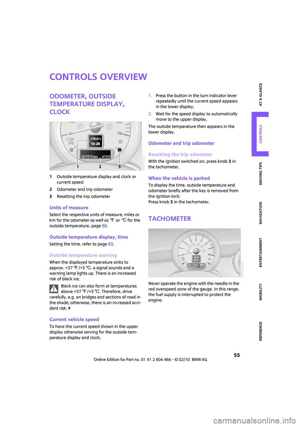
Odometer, outside
temperature display,
clock
1Outside temperature display and clock or
current speed
2Odometer and trip odometer
3Resetting the trip odometer
Units of measure
Select the respective units of measure, miles or
km for the odometer as well as 7 or 6 for the
outside temperature, page60.
Outside temperature display, time
Setting the time, refer to page63.
Outside temperature warning
When the displayed temperature sinks to
approx. +377/+36, a signal sounds and a
warning lamp lights up. There is an increased
risk of black ice.
Black ice can also form at temperatures
above +377/+36. Therefore, drive
carefully, e.g. on bridges and sections of road in
the shade; otherwise, there is an increased acci-
dent risk.<
Current vehicle speed
To have the current speed shown in the upper
display otherwise serving for the outside tem-
perature display and clock.1.Press the button in the turn indicator lever
repeatedly until the current speed appears
in the lower display.
2.Wait for the speed display to automatically
move to the upper display.
The outside temperature then appears in the
lower display.
Odometer and trip odometer
Resetting the trip odometer
With the ignition switched on, press knob 3 in
the tachometer.
When the vehicle is parked
To display the time, outside temperature and
odometer briefly after the key is removed from
the ignition lock:
Press knob 3 in the tachometer.
Tachometer
Never operate the engine with the needle in the
red overspeed zone of the gauge. In this range,
the fuel supply is interrupted to protect the
engine.
Page 59 of 218
MOBILITYAT A GLANCE CONTROLS DRIVING TIPS ENTERTAINMENT
57
NAVIGATION REFERENCE
To reset average fuel consumption: press the
button in the turn indicator lever for approx.
2seconds.
Current fuel consumption
Displays the current fuel consumption to allow
you to see whether your current driving style is
conducive to fuel economy with minimum
exhaust emissions.
Average speed
Periods with the vehicle parked and the engine
switched off are not included in the calculations
of average speed.
With the trip computer, page58, you can have
the average speed for another trip displayed.
To reset average speed: press the button in the
turn indicator lever for approx. 2 seconds.
Current vehicle speed
To have the current speed shown in the upper
display otherwise serving for the outside tem-
perature display and clock.
1.Press the button in the turn indicator lever
repeatedly until the current speed appears
in the lower display.
2.Wait for the speed display to automatically
move to the upper display.
The outside temperature then appears in the
lower display of the computer.
Displays on the Control Display
To access the computer via the onboard moni-
tor, basic operation on page16.
1.Press the button.
This opens the start menu.
2.Move the MINI joystick to highlight "Naviga-
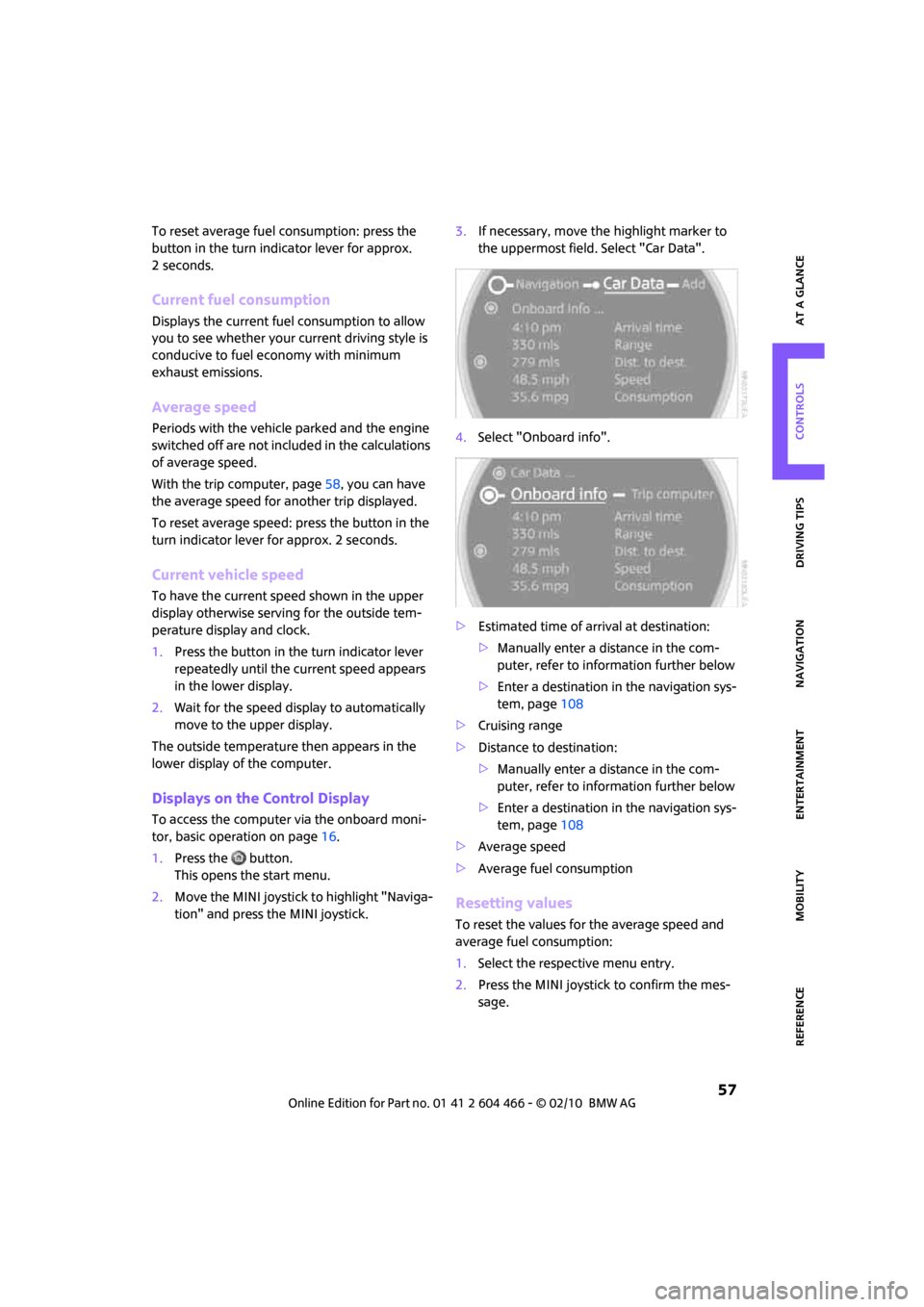
tion" and press the MINI joystick.3.If necessary, move the highlight marker to
the uppermost field. Select "Car Data".
4.Select "Onboard info".
>Estimated time of arrival at destination:
>Manually enter a distance in the com-
puter, refer to information further below
>Enter a destination in the navigation sys-
tem, page108
>Cruising range
>Distance to destination:
>Manually enter a distance in the com-
puter, refer to information further below
>Enter a destination in the navigation sys-
tem, page108
>Average speed
>Average fuel consumption
Resetting values
To reset the values for the average speed and
average fuel consumption:
1.Select the respective menu entry.
2.Press the MINI joystick to confirm the mes-
sage.
Page 65 of 218
MOBILITYAT A GLANCE CONTROLS DRIVING TIPS ENTERTAINMENT
63
NAVIGATION REFERENCE
Clock
In the tachometer
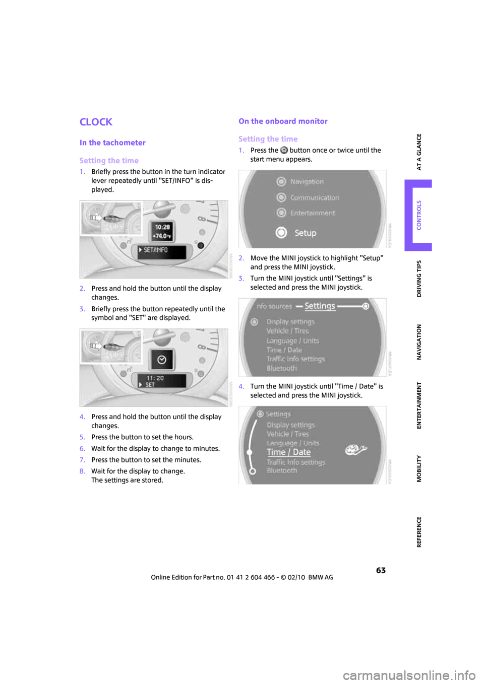
Setting the time
1.Briefly press the button in the turn indicator
lever repeatedly until "SET/INFO" is dis-
played.
2.Press and hold the button until the display
changes.
3.Briefly press the button repeatedly until the
symbol and "SET" are displayed.
4.Press and hold the button until the display
changes.
5.Press the button to set the hours.
6.Wait for the display to change to minutes.
7.Press the button to set the minutes.
8.Wait for the display to change.
The settings are stored.
On the onboard monitor
Setting the time
1.Press the button once or twice until the
start menu appears.
2.Move the MINI joystick to highlight "Setup"
and press the MINI joystick.
3.Turn the MINI joystick until "Settings" is
selected and press the MINI joystick.
4.Turn the MINI joystick until "Time / Date" is
selected and press the MINI joystick.
Page 158 of 218
Refueling
156
Refueling
Switch off the engine before refueling;
otherwise, fuel cannot be added to the
tank and a message will be displayed.<
Take all precautionary measures and
observe all applicable regulations when
handling fuel. Do not carry any spare fuel con-
tainers in your vehicle. They can develop a leak
and cause an explosion or cause a fire in the
event of an accident.<
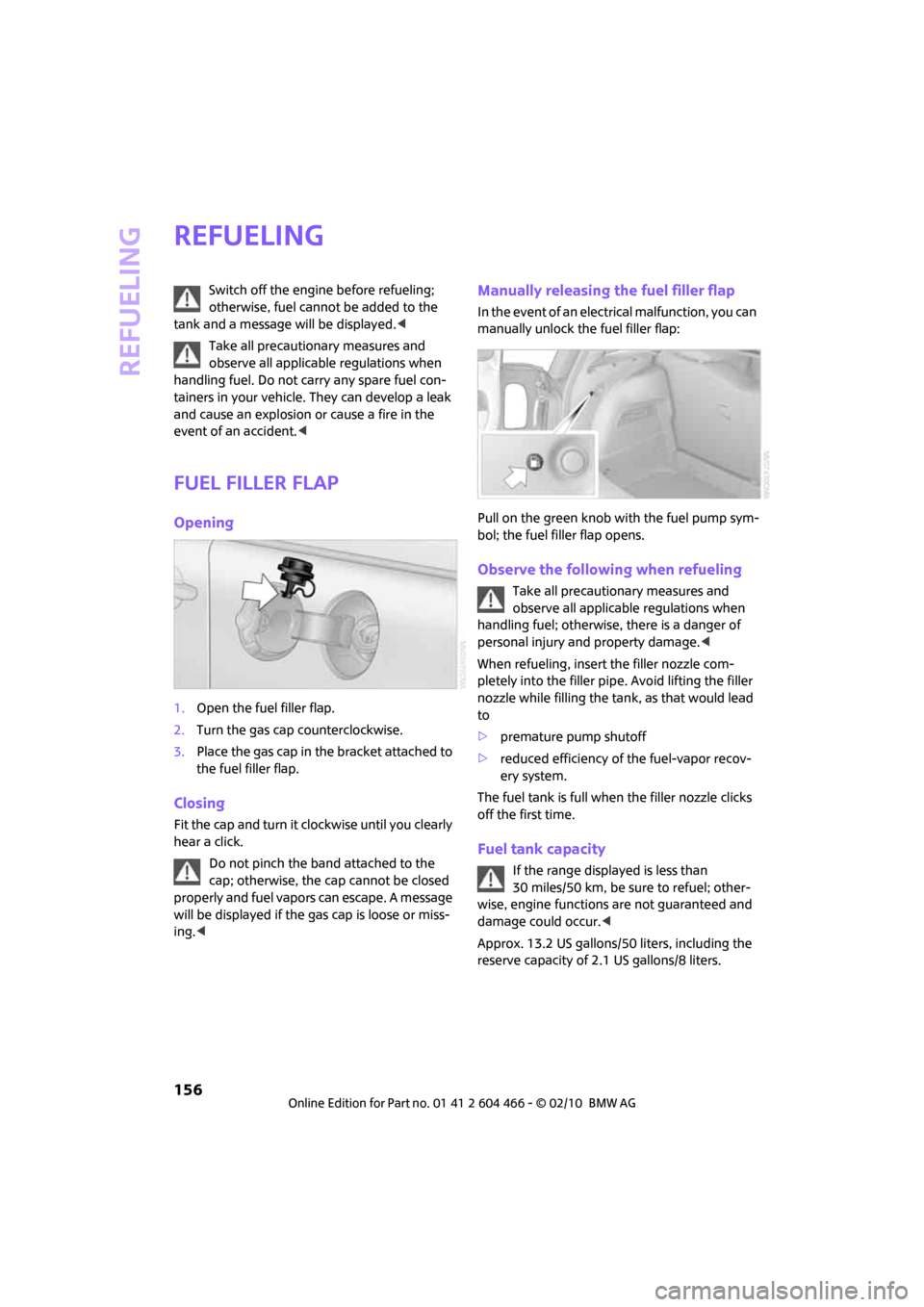
Fuel filler flap
Opening
1.Open the fuel filler flap.
2.Turn the gas cap counterclockwise.
3.Place the gas cap in the bracket attached to
the fuel filler flap.
Closing
Fit the cap and turn it clockwise until you clearly
hear a click.
Do not pinch the band attached to the
cap; otherwise, the cap cannot be closed
properly and fuel vapors can escape. A message
will be displayed if the gas cap is loose or miss-
ing.<
Manually releasing the fuel filler flap
In the event of an electrical malfunction, you can
manually unlock the fuel filler flap:
Pull on the green knob with the fuel pump sym-
bol; the fuel filler flap opens.
Observe the following when refueling
Take all precautionary measures and
observe all applicable regulations when
handling fuel; otherwise, there is a danger of
personal injury and property damage.<
When refueling, insert the filler nozzle com-
pletely into the filler pipe. Avoid lifting the filler
nozzle while filling the tank, as that would lead
to
>premature pump shutoff
>reduced efficiency of the fuel-vapor recov-
ery system.
The fuel tank is full when the filler nozzle clicks
off the first time.
Fuel tank capacity
If the range displayed is less than
30 miles/50 km, be sure to refuel; other-
wise, engine functions are not guaranteed and
damage could occur.<
Approx. 13.2 US gallons/50 liters, including the
reserve capacity of 2.1 US gallons/8 liters.
Page 171 of 218
MOBILITYAT A GLANCE CONTROLS DRIVING TIPS ENTERTAINMENT
169
NAVIGATION REFERENCE
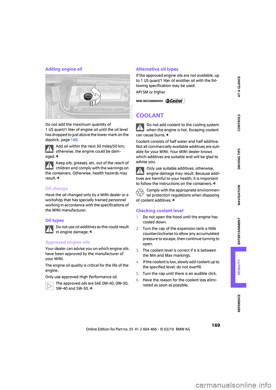
Adding engine oil
Do not add the maximum quantity of
1 US quart/1 liter of engine oil until the oil level
has dropped to just above the lower mark on the
dipstick, page168.
Add oil within the next 30 miles/50 km;
otherwise, the engine could be dam-
aged.<
Keep oils, greases, etc. out of the reach of
children and comply with the warnings on
the containers. Otherwise, health hazards may
result.<
Oil change
Have the oil changed only by a MINI dealer or a
workshop that has specially trained personnel
working in accordance with the specifications of
the MINI manufacturer.
Oil types
Do not use oil additives as this could result
in engine damage.<
Approved engine oils
Your dealer can advise you on which engine oils
have been approved by the manufacturer of
your MINI.
The engine oil quality is critical for the life of the
engine.
Only use approved High Performance oil.
The approved oils are SAE 0W-40, 0W-30,
5W-40 and 5W-30.<
Alternative oil types
If the approved engine oils are not available, up
to 1 US quart/1 liter of another oil with the fol-
lowing specification may be used:
API SM or higher
Coolant
Do not add coolant to the cooling system
when the engine is hot. Escaping coolant
can cause burns.<
Coolant consists of half water and half additive.
Not all commercially available additives are suit-
able for your MINI. Your MINI dealer knows
which additives are suitable and will be glad to
advise you.
Only use suitable additives; otherwise,
engine damage may result. Because addi-
tives are harmful to your health, it is important
to follow the instructions on the containers.<
Comply with the appropriate environmen-
tal protection regulations when disposing
of coolant additives.<
Checking coolant level
1.Do not open the hood until the engine has
cooled down.
2.Turn the cap of the expansion tank a little
counterclockwise to allow any accumulated
pressure to escape, then continue turning to
open.
3.The coolant level is correct if it is between
the Min and Max markings.
4.If the coolant is low, slowly add coolant up to
the specified level; do not overfill.
5.Turn the cap until there is an audible click.
6.Have the reason for the coolant loss elimi-
nated as soon as possible.
Page 180 of 218
Replacing components
178
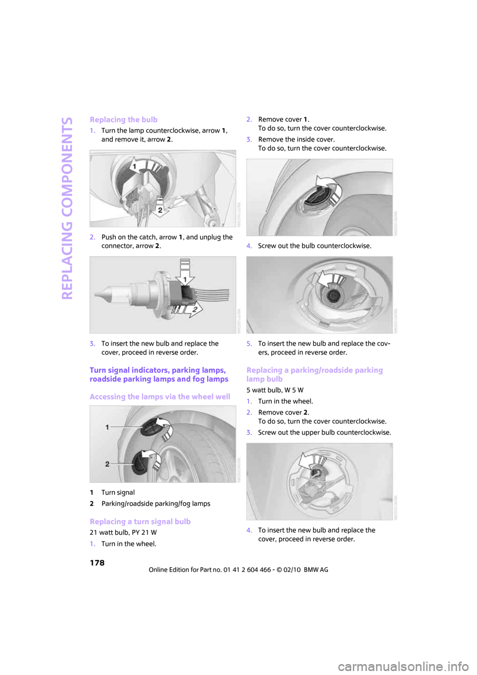
Replacing the bulb
1.Turn the lamp counterclockwise, arrow1,
and remove it, arrow2.
2.Push on the catch, arrow 1, and unplug the
connector, arrow2.
3.To insert the new bulb and replace the
cover, proceed in reverse order.
Turn signal indicators, parking lamps,
roadside parking lamps and fog lamps
Accessing the lamps via the wheel well
1Turn signal
2Parking/roadside parking/fog lamps
Replacing a turn signal bulb
21 watt bulb, PY 21 W
1.Turn in the wheel.2.Remove cover 1.
To do so, turn the cover counterclockwise.
3.Remove the inside cover.
To do so, turn the cover counterclockwise.
4.Screw out the bulb counterclockwise.
5.To insert the new bulb and replace the cov-
ers, proceed in reverse order.
Replacing a parking/roadside parking
lamp bulb
5 watt bulb, W 5 W
1.Turn in the wheel.
2.Remove cover 2.
To do so, turn the cover counterclockwise.
3.Screw out the upper bulb counterclockwise.
4.To insert the new bulb and replace the
cover, proceed in reverse order.
Page 181 of 218
MOBILITYAT A GLANCE CONTROLS DRIVING TIPS ENTERTAINMENT
179
NAVIGATION REFERENCE
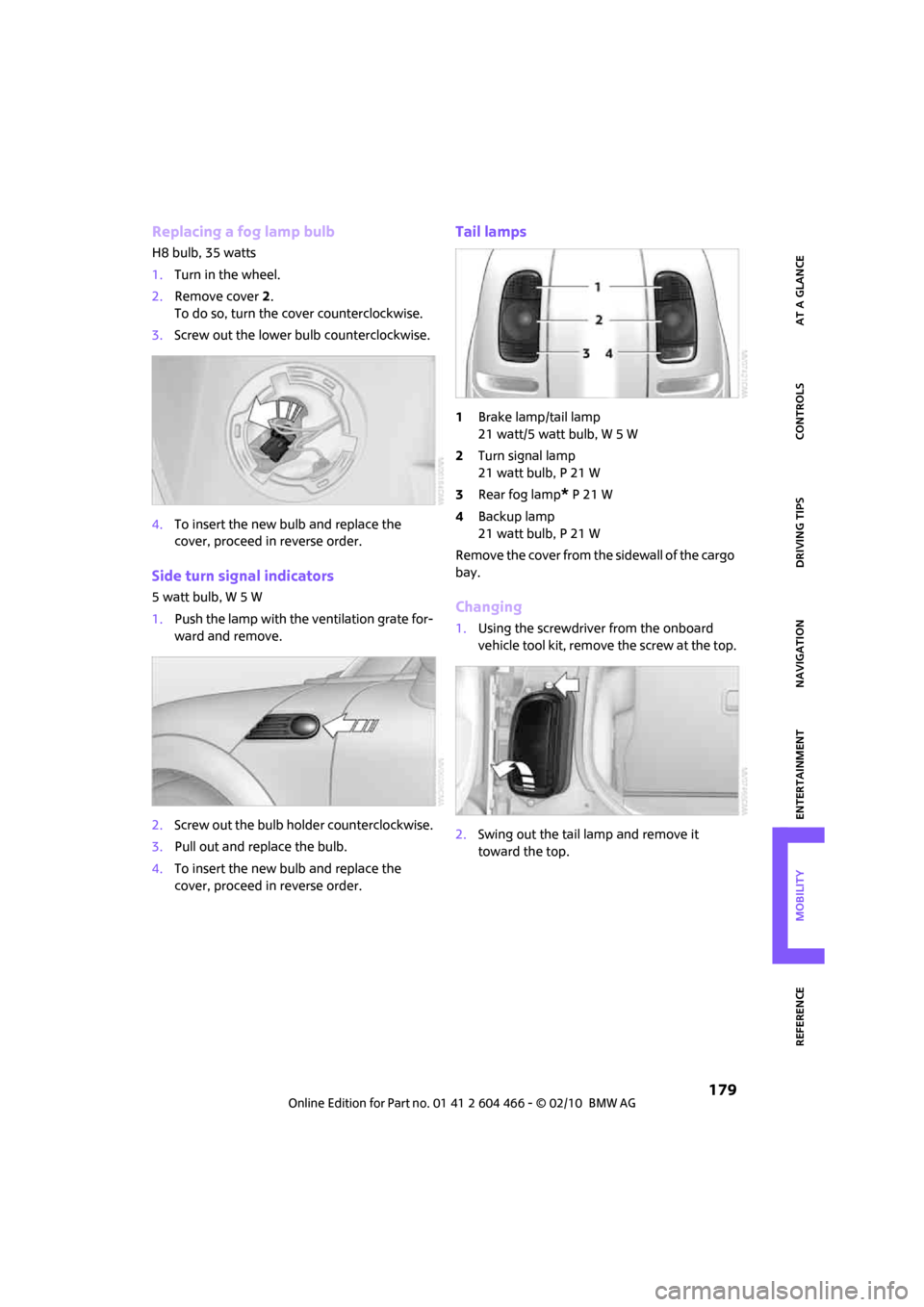
Replacing a fog lamp bulb
H8 bulb, 35 watts
1.Turn in the wheel.
2.Remove cover 2.
To do so, turn the cover counterclockwise.
3.Screw out the lower bulb counterclockwise.
4.To insert the new bulb and replace the
cover, proceed in reverse order.
Side turn signal indicators
5 watt bulb, W 5 W
1.Push the lamp with the ventilation grate for-
ward and remove.
2.Screw out the bulb holder counterclockwise.
3.Pull out and replace the bulb.
4.To insert the new bulb and replace the
cover, proceed in reverse order.
Tail lamps
1Brake lamp/tail lamp
21 watt/5 watt bulb, W 5 W
2Turn signal lamp
21 watt bulb, P 21 W
3Rear fog lamp
* P 21 W
4Backup lamp
21 watt bulb, P 21 W
Remove the cover from the sidewall of the cargo
bay.
Changing
1.Using the screwdriver from the onboard
vehicle tool kit, remove the screw at the top.
2.Swing out the tail lamp and remove it
toward the top.