change time MINI Clubman 2010 User Guide
[x] Cancel search | Manufacturer: MINI, Model Year: 2010, Model line: Clubman, Model: MINI Clubman 2010Pages: 160, PDF Size: 2.58 MB
Page 65 of 160
REFERENCEAT A GLANCE CONTROLS DRIVING TIPS MOBILITY
63
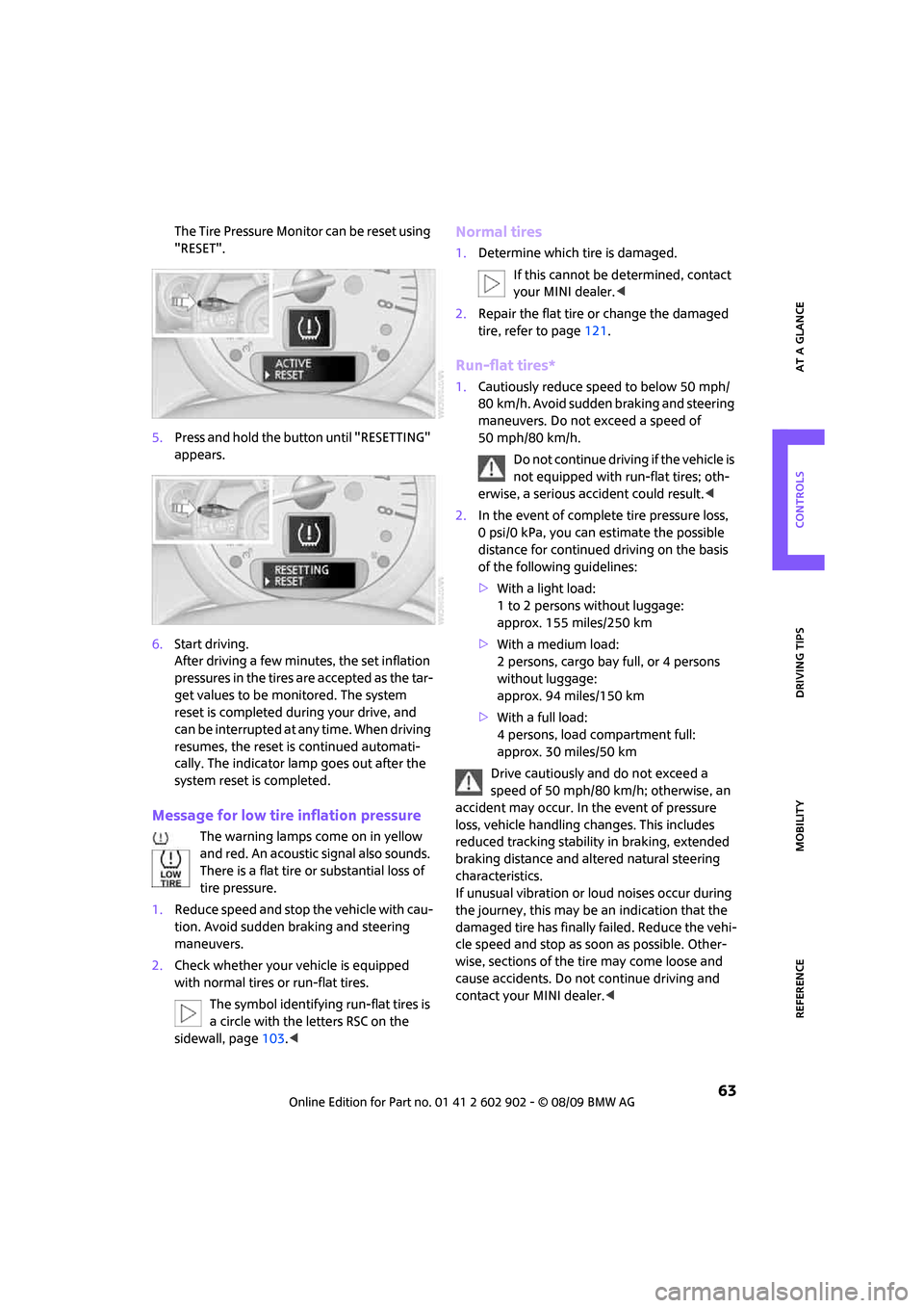
The Tire Pressure Monitor can be reset using
"RESET".
5.Press and hold the button until "RESETTING"
appears.
6.Start driving.
After driving a few minutes, the set inflation
pressures in the tires are accepted as the tar-
get values to be monitored. The system
reset is completed during your drive, and
can be interrupted at any time. When driving
resumes, the reset is continued automati-
cally. The indicator lamp goes out after the
system reset is completed.
Message for low tire inflation pressure
The warning lamps come on in yellow
and red. An acoustic signal also sounds.
There is a flat tire or substantial loss of
tire pressure.
1.Reduce speed and stop the vehicle with cau-
tion. Avoid sudden braking and steering
maneuvers.
2.Check whether your vehicle is equipped
with normal tires or run-flat tires.
The symbol identifying run-flat tires is
a circle with the letters RSC on the
sidewall, page103.<
Normal tires
1.Determine which tire is damaged.
If this cannot be determined, contact
your MINI dealer.<
2.Repair the flat tire or change the damaged
tire, refer to page121.
Run-flat tires*
1.Cautiously reduce speed to below 50 mph/
80 km/h. Avoid sudden braking and steering
maneuvers. Do not exceed a speed of
50 mph/80 km/h.
Do not continue driving if the vehicle is
not equipped with run-flat tires; oth-
erwise, a serious accident could result.<
2.In the event of complete tire pressure loss,
0 psi/0 kPa, you can estimate the possible
distance for continued driving on the basis
of the following guidelines:
>With a light load:
1 to 2 persons without luggage:
approx. 155 miles/250 km
>With a medium load:
2 persons, cargo bay full, or 4 persons
without luggage:
approx. 94 miles/150 km
>With a full load:
4 persons, load compartment full:
approx. 30 miles/50 km
Drive cautiously and do not exceed a
speed of 50 mph/80 km/h; otherwise, an
accident may occur. In the event of pressure
loss, vehicle handling changes. This includes
reduced tracking stability in braking, extended
braking distance and altered natural steering
characteristics.
If unusual vibration or loud noises occur during
the journey, this may be an indication that the
damaged tire has finally failed. Reduce the vehi-
cle speed and stop as soon as possible. Other-
wise, sections of the tire may come loose and
cause accidents. Do not continue driving and
contact your MINI dealer.<
Page 68 of 160
Technology for driving comfort and safety
66
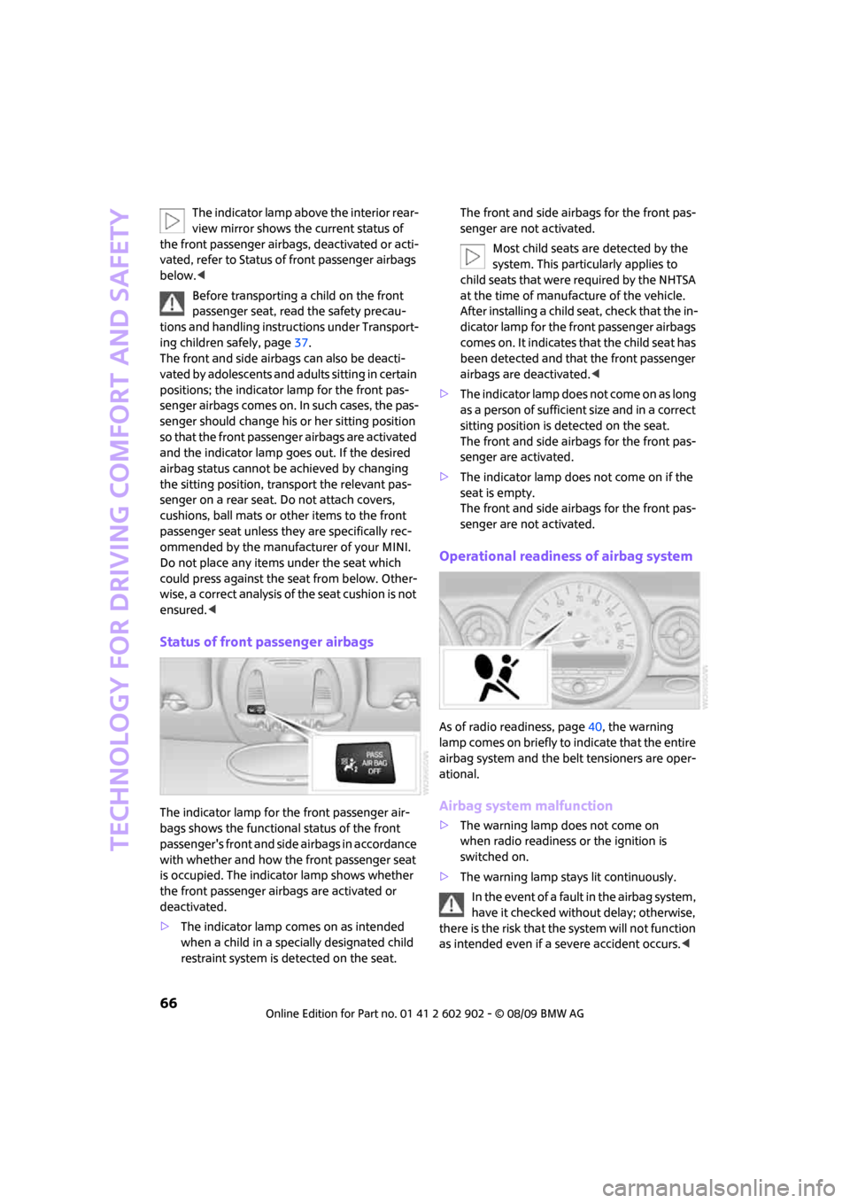
The indicator lamp above the interior rear-
view mirror shows the current status of
the front passenger airbags, deactivated or acti-
vated, refer to Status of front passenger airbags
below.<
Before transporting a child on the front
passenger seat, read the safety precau-
tions and handling instructions under Transport-
ing children safely, page37.
The front and side airbags can also be deacti-
vated by adolescents and adults sitting in certain
positions; the indicator lamp for the front pas-
senger airbags comes on. In such cases, the pas-
senger should change his or her sitting position
so that the front passenger airbags are activated
and the indicator lamp goes out. If the desired
airbag status cannot be achieved by changing
the sitting position, transport the relevant pas-
senger on a rear seat. Do not attach covers,
cushions, ball mats or other items to the front
passenger seat unless they are specifically rec-
ommended by the manufacturer of your MINI.
Do not place any items under the seat which
could press against the seat from below. Other-
wise, a correct analysis of the seat cushion is not
ensured.<
Status of front passenger airbags
The indicator lamp for the front passenger air-
bags shows the functional status of the front
passenger's front and side airbags in accordance
with whether and how the front passenger seat
is occupied. The indicator lamp shows whether
the front passenger airbags are activated or
deactivated.
>The indicator lamp comes on as intended
when a child in a specially designated child
restraint system is detected on the seat.The front and side airbags for the front pas-
senger are not activated.
Most child seats are detected by the
system. This particularly applies to
child seats that were required by the NHTSA
at the time of manufacture of the vehicle.
After installing a child seat, check that the in-
dicator lamp for the front passenger airbags
comes on. It indicates that the child seat has
been detected and that the front passenger
airbags are deactivated.<
>T h e i n d i c a t o r l a m p d o e s n o t c o m e o n a s l o n g
as a person of sufficient size and in a correct
sitting position is detected on the seat.
The front and side airbags for the front pas-
senger are activated.
>The indicator lamp does not come on if the
seat is empty.
The front and side airbags for the front pas-
senger are not activated.
Operational readiness of airbag system
As of radio readiness, page40, the warning
lamp comes on briefly to indicate that the entire
airbag system and the belt tensioners are oper-
ational.
Airbag system malfunction
>The warning lamp does not come on
when radio readiness or the ignition is
switched on.
>The warning lamp stays lit continuously.
In the event of a fault in the airbag system,
have it checked without delay; otherwise,
there is the risk that the system will not function
as intended even if a severe accident occurs.<
Page 70 of 160
Lamps
68
Setting the duration or deactivating the
function
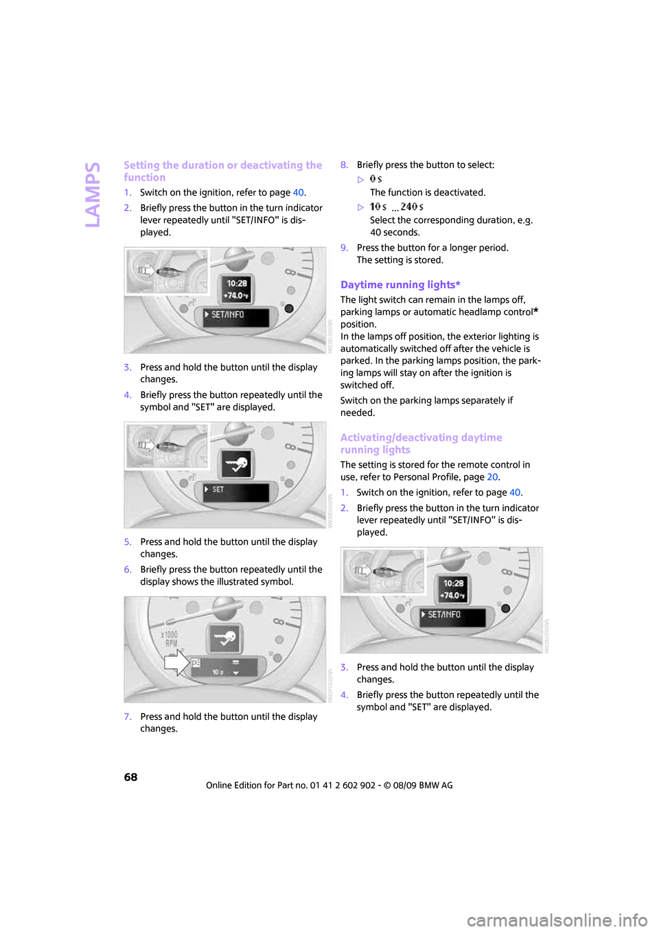
1.Switch on the ignition, refer to page40.
2.Briefly press the button in the turn indicator
lever repeatedly until "SET/INFO" is dis-
played.
3.Press and hold the button until the display
changes.
4.Briefly press the button repeatedly until the
symbol and "SET" are displayed.
5.Press and hold the button until the display
changes.
6.Briefly press the button repeatedly until the
display shows the illustrated symbol.
7.Press and hold the button until the display
changes.8.Briefly press the button to select:
>
The function is deactivated.
> ...
Select the corresponding duration, e.g.
40 seconds.
9.Press the button for a longer period.
The setting is stored.
Daytime running lights*
The light switch can remain in the lamps off,
parking lamps or automatic headlamp control
*
position.
In the lamps off position, the exterior lighting is
automatically switched off after the vehicle is
parked. In the parking lamps position, the park-
ing lamps will stay on after the ignition is
switched off.
Switch on the parking lamps separately if
needed.
Activating/deactivating daytime
running lights
The setting is stored for the remote control in
use, refer to Personal Profile, page20.
1.Switch on the ignition, refer to page40.
2.Briefly press the button in the turn indicator
lever repeatedly until "SET/INFO" is dis-
played.
3.Press and hold the button until the display
changes.
4.Briefly press the button repeatedly until the
symbol and "SET" are displayed.
Page 71 of 160
REFERENCEAT A GLANCE CONTROLS DRIVING TIPS MOBILITY
69
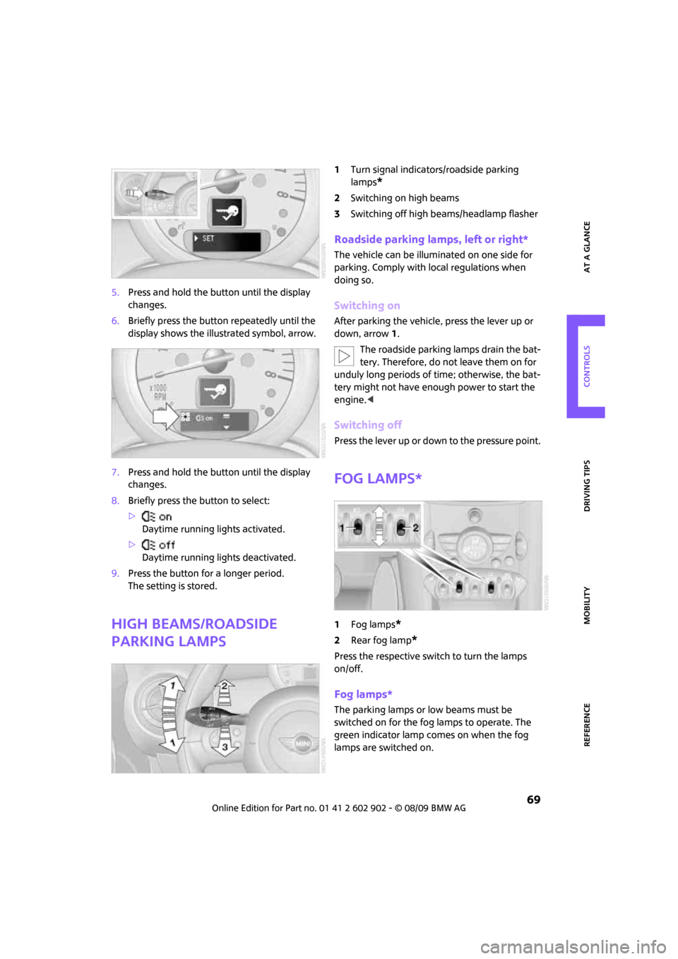
5.Press and hold the button until the display
changes.
6.Briefly press the button repeatedly until the
display shows the illustrated symbol, arrow.
7.Press and hold the button until the display
changes.
8.Briefly press the button to select:
>
Daytime running lights activated.
>
Daytime running lights deactivated.
9.Press the button for a longer period.
The setting is stored.
High beams/roadside
parking lamps
1Turn signal indicators/roadside parking
lamps
*
2Switching on high beams
3Switching off high beams/headlamp flasher
Roadside parking lamps, left or right*
The vehicle can be illuminated on one side for
parking. Comply with local regulations when
doing so.
Switching on
After parking the vehicle, press the lever up or
down, arrow 1.
The roadside parking lamps drain the bat-
tery. Therefore, do not leave them on for
unduly long periods of time; otherwise, the bat-
tery might not have enough power to start the
engine.<
Switching off
Press the lever up or down to the pressure point.
Fog lamps*
1Fog lamps*
2Rear fog lamp*
Press the respective switch to turn the lamps
on/off.
Fog lamps*
The parking lamps or low beams must be
switched on for the fog lamps to operate. The
green indicator lamp comes on when the fog
lamps are switched on.
Page 76 of 160
Climate
74
Air distribution
Direct the flow of air to the win-
dows , to the upper body area
or to the footwell . Interme-
diate settings are possible.
Windshield heating*
The windshield heating is switched
off automatically after a short time.
Defrosting windows and removing
condensation
1.Set air flow rate to the maximum level.
2.Set air distribution to position .
Condensation is removed from the windows more quickly when the cooling function
* is
also activated.
3.Set to the highest temperature, red.
4.Deactivate recirculated-air mode.
5.Turn on windshield heating if necessary.
6.Turn on rear window defroster if necessary.
Microfilter
The microfilter captures dust and pollen. The
microfilter is changed by your MINI dealer dur-
ing routine maintenance work.
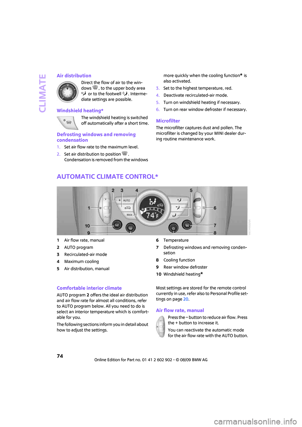
Automatic climate control*
1Air flow rate, manual
2AUTO program
3Recirculated-air mode
4Maximum cooling
5Air distribution, manual6Temperature
7Defrosting windows and removing conden-
sation
8Cooling function
9Rear window defroster
10Windshield heating
*
Comfortable interior climate
AUTO program2 offers the ideal air distribution
and air flow rate for almost all conditions, refer
to AUTO program below. All you need to do is
select an interior temperature which is comfort-
able for you.
The following sections inform you in detail about
how to adjust the settings.Most settings are stored for the remote control
currently in use, refer also to Personal Profile set-
tings on page20.
Air flow rate, manual
Press the – button to reduce air flow. Press
the + button to increase it.
You can reactivate the automatic mode
for the air flow rate with the AUTO button.
Page 77 of 160
REFERENCEAT A GLANCE CONTROLS DRIVING TIPS MOBILITY
75
The air flow rate is lowered or switched off
entirely to save on battery power. The display
remains the same.
Switching the system on/off
Reduce the air flow by pressing the – button
repeatedly until the system is switched off. All
indicators go out.
Press the AUTO button to switch the automatic
climate control back on.
AUTO program
The AUTO program adjusts the air
distribution to the windshield and
side windows, towards the upper body area and
into the footwell for you. The air flow rate and
your temperature specifications will be adapted
to outside influences in accordance with sea-
sonal changes, e.g. sunlight.
The cooling function is automatically switched
on along with the AUTO program.
Recirculated-air mode
Recirculated-air mode: the supply
of outside air is permanently shut
off. The system then recirculates
the air currently within the vehicle.
If condensation starts to form on the
inside window surfaces, press the AUTO
button or switch off the recirculated-air mode
and, if necessary, increase the air flow rate.
The recirculated-air mode should not be used
over an extended period of time; otherwise, the
air quality inside the car will deteriorate contin-
uously.<
Maximum cooling
At outside temperatures above
327/06 and when the engine is
running, you obtain a maximum
cooling effect as soon as possible.
The automatic climate control goes into recircu-
lated-air mode at the lowest temperature. Air
flows at maximum rate from the vents for the
upper body area. You should therefore open
them for maximum cooling.
Air distribution, manual
The flow of air is directed to the
windows, to the upper body area or
to the footwell as selected.
You can switch the automatic air
distribution back on by pressing the AUTO
button.
Temperature
Set the desired temperature individually.
The automatic climate control achieves
this temperature as quickly as possible
regardless of the season, using maximum
cooling or heating power if necessary, and then
maintains it.
If you switch between different tempera-
ture settings in quick succession, the auto-
matic climate control does not have enough
time to achieve the set temperature.<
Rear window defroster
The defroster is switched off auto-
matically after a certain time.
Depending on your vehicle's equip-
ment, the upper wires serve as an
antenna and are not part of the rear window
defroster.
Defrosting windows and removing
condensation
Quickly removes ice and condensa-
tion from the windshield and front
side windows.
For this purpose, also switch on the
cooling function.
The windshield heating
* is switched on auto-
matically.
Windshield heating*
The windshield heating is switched
off automatically after a certain
time.
Page 113 of 160
REFERENCEAT A GLANCE CONTROLS DRIVING TIPS MOBILITY
111
Steam jets/high-pressure washers
When using steam jets or high-pressure
washers, ensure that you maintain suffi-
cient clearance to the vehicle and do not exceed
a temperature of 1407/606.
If the distance is too close, the pressure too high,
or the temperature too high, parts of the vehicle
can be damaged, or water can penetrate.
Observe the operating instructions for high-
pressure washers.<
Do not spray sensors such as Park Dis-
tance Control with high-pressure washers
for a long time or at a distance of less than
1 ft/30 cm.<
Manual washing
Use a great deal of water and, if necessary, car
shampoo when washing your car by hand. Clean
the vehicle with a sponge or a washing brush
applying a slight amount of pressure.
Before cleaning the windshield, deacti-
vate the rain sensor or turn off the ignition
to prevent unintentional wiping.<
Observe local regulations regarding wash-
ing vehicles by hand.<
Headlamps
Do not wipe dry and do not use abrasive or cor-
rosive cleaning agents. Remove dirt and con-
tamination, such as insects, by soaking with
shampoo and then washing with plenty of
water.
Do not remove accumulated ice and snow with
an ice scraper; use window deicers instead.
Windows
Clean the outside and inside of the windows and
mirrors with a window cleaner.
Do not clean the mirrors with cleaners
containing quartz.<
Wiper blades
Clean with soapy water and change regularly to
prevent the formation of streaks.
Wax, preservatives and dirt on the win-
dows cause streaks when the windshield wipers are on, and can cause premature wear
of the wiper blades and interfere with the rain
sensor.<
Paintwork, care
Regular care helps your vehicle retain its value
and protects the paint from the long-term
effects of aggressive substances.
In some regions, environmental factors can
affect the vehicle paintwork and damage it. It is
therefore important to adjust the frequency and
extent of vehicle care correspondingly.
Immediately remove aggressive materials such
as spilled fuel, oil, grease, brake fluid, tree sap
or bird droppings to prevent damage to the
paintwork.
Removing paintwork damage
Depending on the severity of the damage,
immediately repair stone damage or
scratches to prevent rusting.<
The manufacturer of the MINI recommends
repairing paint damage professionally according
to factory specifications with original MINI
paints.
Preservation
Preservation is necessary when water no longer
beads on the clean paint surface. To preserve
the paint, only use preservatives that contain
carnauba or synthetic waxes.
Rubber seals
Only treat with water or rubber care products.
Do not use silicon sprays or other silicon-
containing care products on rubber seals;
otherwise, noise and damage could occur.<
Chrome parts*
Carefully clean vehicle parts such as the radiator
grill and door handles with copious quantities of
water and, if necessary, a shampoo additive,
especially when contaminated with road salt.
For additional treatment, use chrome polish.
Page 117 of 160
REFERENCEAT A GLANCE CONTROLS DRIVING TIPS MOBILITY
115
When working on electrical systems,
always begin by switching off the con-
sumer in question; otherwise, short circuits
could result. To avoid possible injury or equip-
ment damage when replacing bulbs, observe
any instructions provided by the bulb manufac-
turer.<
Caring for headlamps, refer to page111.
For any bulb replacement not described
below, contact a MINI dealer or a work-
shop that has specially trained personnel work-
ing in accordance with the specifications of the
MINI manufacturer.<
For checking and adjusting headlamp aim,
please contact your MINI dealer.<
Light-emitting diodes LEDs
Light-emitting diodes installed behind translu-
cent lenses serve as the light sources for many of
the controls and displays in your vehicle. These
light-emitting diodes are related to conven-
tional laser diodes, and legislation defines them
as Class 1 light-emitting diodes.
Do not remove the covers or expose the
eyes directly to the unfiltered light source
for several hours; otherwise, this could cause
irritation of the retina.<
Xenon lamps*
The service life of these bulbs is very long and
the probability of failure very low, provided that
they are not switched on and off an excessive
number of times. If a xenon lamp fails neverthe-
less, switch on the fog lamps and continue the
journey with great care, provided that local leg-
islation does not prohibit this.
Have any work on the xenon lamp system,
including bulb replacement, carried out
only by a MINI dealer or a workshop that has
specially trained personnel working in accor-
dance with the specifications of the MINI manu-
facturer. Due to high voltage, there is a risk of
fatal injury if work on the xenon lamps is carried
out improperly.<
Halogen low beams and high beams
H13 bulb, 60/55 watts
The H13 bulb is pressurized. Therefore,
wear safety glasses and protective gloves.
Otherwise, there is a risk of injury if the bulb is
damaged.<
Be careful when installing the cover; oth-
erwise, leaks could occur and cause dam-
age to the headlamp system.<
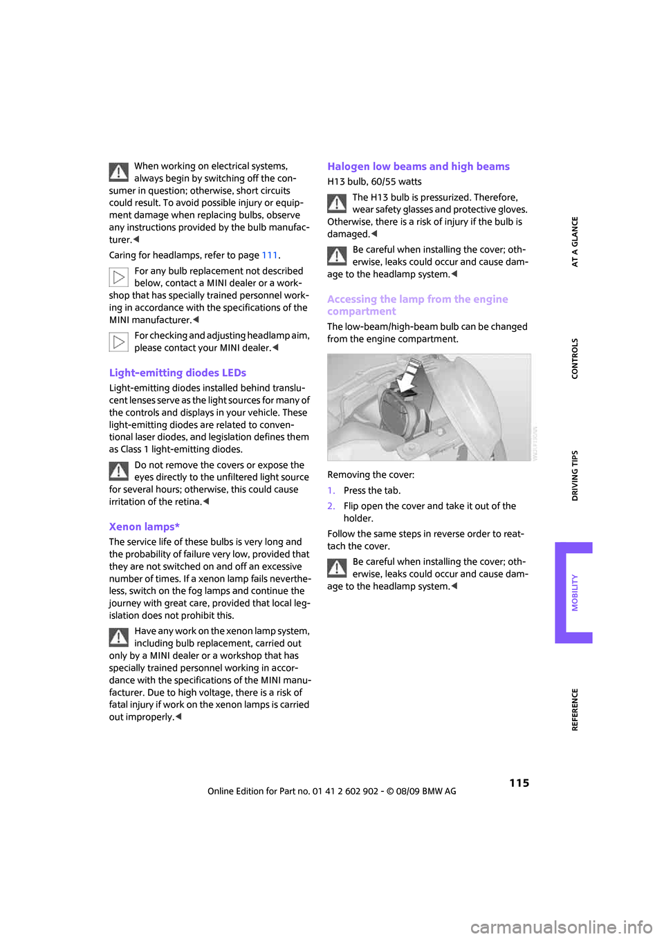
Accessing the lamp from the engine
compartment
The low-beam/high-beam bulb can be changed
from the engine compartment.
Removing the cover:
1.Press the tab.
2.Flip open the cover and take it out of the
holder.
Follow the same steps in reverse order to reat-
tach the cover.
Be careful when installing the cover; oth-
erwise, leaks could occur and cause dam-
age to the headlamp system.<
Page 123 of 160

REFERENCEAT A GLANCE CONTROLS DRIVING TIPS MOBILITY
121
Changing wheels
Space-saver spare tire*
To change a space-saver spare tire, proceed as
follows:
>Remove the space-saver spare tire,
page121
>Prepare for tire change, page121
>Jack up vehicle, page122
>Mount space-saver spare tire, page122
>Tighten lug bolts, page122
>Drive with space-saver spare tire, page121
Tire change set for a space-saver
spare tire*
In vehicles with the space-saver spare tire, the
tire change set with the onboard vehicle tool kit
is located beneath the floor mat or level load
floor in the cargo bay.
1Folding chock and cover for defective wheel
2Vehicle jack
3Wheel stud wrench
4Hub cover remover
5Flat screwdriver/Phillips screwdriver
6Torx insert bit for screwdriver
7Towing eyelet
The onboard vehicle tool kit includes a pouch
with a plastic bag in which you can place the
damaged wheel.
Removing the space-saver spare tire
The space-saver spare tire is located under the
tire change set in the cargo bay.
1.Fold up the floor mat.
2.Unscrew the nut, arrow, and remove the
space-saver spare tire.
Driving with the space-saver spare tire
Drive cautiously and do not exceed a
speed of 50 mph/80 km/h. Changes may
occur in vehicle handling such as lower track sta-
bility during braking, longer braking distances
and changes in self-steering properties when
close to the handling limit. These properties are
more noticeable with winter tires.<
Only one space-saver spare tire may be
mounted at one time. Mount a wheel and
tire of the original size as soon as possible, to
avoid any safety risks.<
Check the tire inflation pressure at the ear-
liest opportunity and correct it if neces-
sary. Replace the defective tire as soon as possi-
ble and have the new wheel/tire assembly
balanced.<
Preparing for a tire change
Observe the safety precautions regarding
flat tires on page118.<
Additional safety measures when chang-
ing tires:
Only change the tire when parked on a surface
that is level, firm and not slippery.
The vehicle or the jack could slip sideways on
soft or slippery support surfaces, such as snow,
ice, flagstones, etc.
Page 125 of 160
REFERENCEAT A GLANCE CONTROLS DRIVING TIPS MOBILITY
123
Vehicle battery
Maintenance
The battery is 100 % maintenance-free, the
electrolyte will last for the life of the battery
when the vehicle is operated in a temperate
climate.
Battery replacement
Only use vehicle batteries that have been
approved for your vehicle by the manu-
facturer; otherwise, the vehicle could be dam-
aged and systems or functions may not be fully
available.<
After a battery replacement, have the battery
registered on the vehicle by your dealer to
ensure that all comfort functions are fully
available.
Charging the battery
Only charge the battery in the vehicle when the
engine is off. Connections, refer to Jump-start-
ing on page124.
Disposal
After replacing old batteries, return the
used batteries to your MINI dealer or to a
recycling point. Maintain the battery in an
upright position for transport and storage.
Always secure the battery against tipping over
during transport.<
Power failure
After a temporary power loss, some equipment
may not be fully functional and may require ini-
tialization. Individual settings are also lost and
must be reprogrammed:
>Time and date
These values must be updated, page55.
>Radio
Stations must be stored again, refer to the
separate Owner's Manual for Radio.
>Glass sunroof
*, electric
It may only be possible to raise the sunroof,
if applicable. The system must be initialized.
Contact your nearest MINI dealer.
Fuses
Do not attempt to repair a blown fuse or
replace it with a fuse of a different color or
Ampere rating. To do this could cause a fire in
the vehicle resulting from a circuit overload.
Have the fuse changed only by a MINI dealer or
a workshop that has specially trained personnel
working in accordance with the specifications of
the MINI manufacturer.<
A fuse allocation diagram is located on the inside
of the fuse box cover panels.
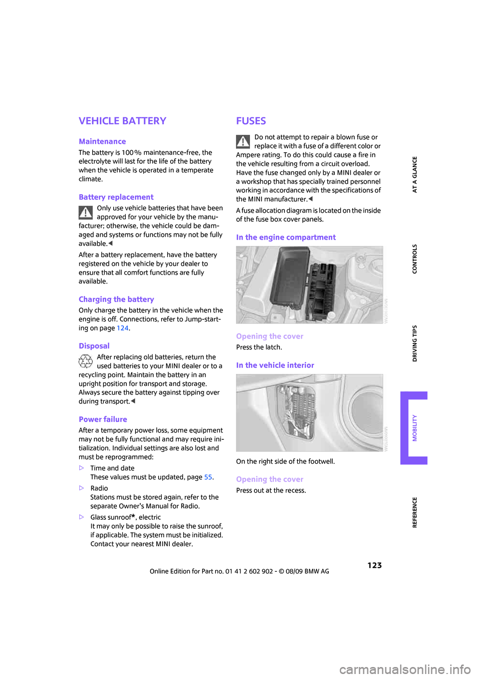
In the engine compartment
Opening the cover
Press the latch.
In the vehicle interior
On the right side of the footwell.
Opening the cover
Press out at the recess.