light MINI Clubman 2011 Owner's Manual (Mini Connected)
[x] Cancel search | Manufacturer: MINI, Model Year: 2011, Model line: Clubman, Model: MINI Clubman 2011Pages: 256, PDF Size: 3.75 MB
Page 12 of 256
AT A GLANCECockpit
10
Cockpit
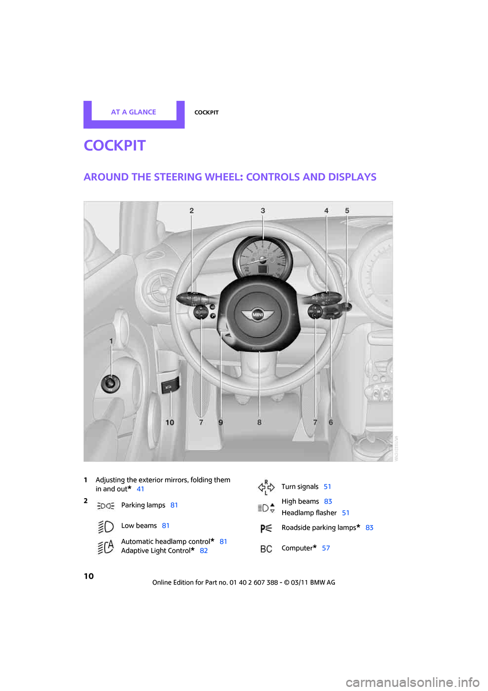
Around the steering wheel: controls and displays
1Adjusting the exterior mirrors, folding them
in and out
*41
2
Parking lamps 81
Low beams 81
Automatic headlamp control
*81
Adaptive Light Control
*82
Turn signals 51
High beams 83
Headlamp flasher 51
Roadside parking lamps
*83
Computer
*57
Page 13 of 256
CockpitAT A GLANCE
11
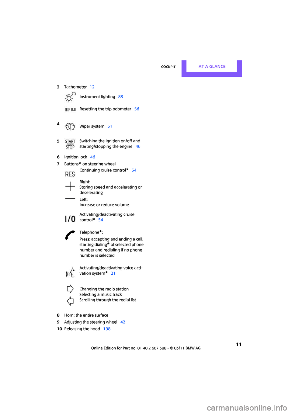
6Ignition lock 46
7 Buttons
* on steering wheel
8 Horn: the entire surface
9 Adjusting the steering wheel 42
10 Releasing the hood 198
3
Tachometer 12
Instrument lighting 83
Resetting the trip odometer 56
4 Wiper system 51
5 Switching the ignition on/off and
starting/stopping the engine
46
Continuing cruise control
*54
Right:
Storing speed and accelerating or
decelerating
Left:
Increase or reduce volume
Activating/deactivating cruise
control
*54
Telephone
*:
Press: accepting an d ending a call,
starting dialing
* of selected phone
number and redialing if no phone
number is selected
Activating/deactivating voice acti-
vation system
*21
Changing the radio station
Selecting a music track
Scrolling through the redial list
Page 14 of 256
AT A GLANCECockpit
12
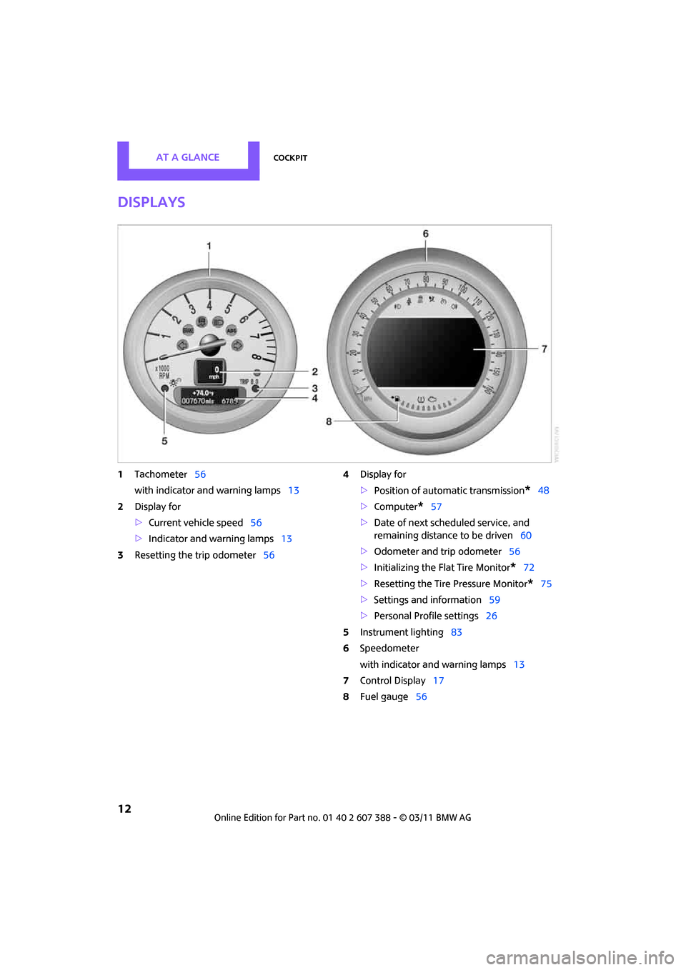
Displays
1Tachometer 56
with indicator and warning lamps 13
2 Display for
>Current vehicle speed 56
> Indicator and warning lamps 13
3 Resetting the trip odometer 564
Display for
>Position of automatic transmission
*48
> Computer
*57
> Date of next scheduled service, and
remaining distance to be driven 60
> Odometer and trip odometer 56
> Initializing the Flat Tire Monitor
*72
> Resetting the Tire Pressure Monitor
*75
> Settings and information 59
> Personal Prof ile settings26
5 Instrument lighting 83
6 Speedometer
with indicator and warning lamps 13
7 Control Display 17
8 Fuel gauge 56
Page 15 of 256
CockpitAT A GLANCE
13
Indicator and warning
lamps
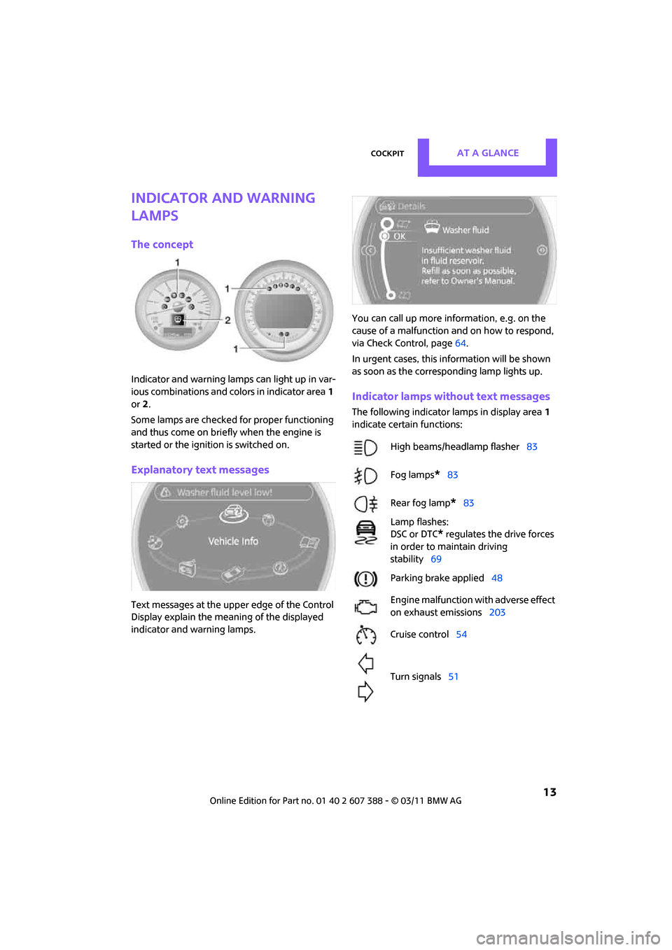
The concept
Indicator and warning lamps can light up in var-
ious combinations and colors in indicator area1
or 2.
Some lamps are checked for proper functioning
and thus come on briefly when the engine is
started or the ignition is switched on.
Explanatory text messages
Text messages at the uppe r edge of the Control
Display explain the mean ing of the displayed
indicator and warning lamps. You can call up more information, e.g. on the
cause of a malfunction and on how to respond,
via Check Control, page
64.
In urgent cases, this information will be shown
as soon as the corresponding lamp lights up.
Indicator lamps without text messages
The following indicator lamps in display area 1
indicate certain functions:
High beams/headlamp flasher 83
Fog lamps
*83
Rear fog lamp
*83
Lamp flashes:
DSC or DTC
* regulates the drive forces
in order to maintain driving
stability 69
Parking brake applied 48
Engine malfunction with adverse effect
on exhaust emissions 203
Cruise control 54
Turn signals 51
Page 17 of 256
CockpitAT A GLANCE
15
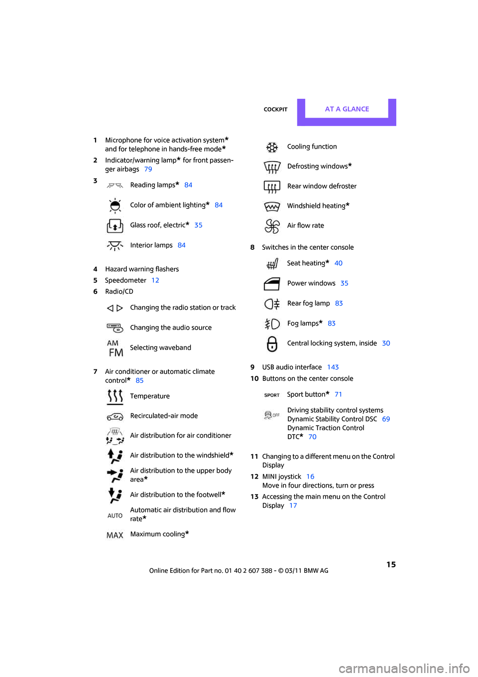
1Microphone for voice activation system*
and for telephone in hands-free mode*
2Indicator/warning lamp* for front passen-
ger airbags 79
4 Hazard warning flashers
5 Speedometer 12
6 Radio/CD
7 Air conditioner or automatic climate
control
*85 8
Switches in the center console
9 USB audio interface 143
10 Buttons on the center console
11 Changing to a differen t menu on the Control
Display
12 MINI joystick 16
Move in four directions, turn or press
13 Accessing the main me nu on the Control
Display 17
3
Reading lamps
*84
Color of ambient lighting
*84
Glass roof, electric
*35
Interior lamps 84
Changing the radio station or track
Changing the audio source
Selecting waveband
Temperature
Recirculated-air mode
Air distribution for air conditioner
Air distribution to the windshield
*
Air distribution to the upper body
area
*
Air distribution to the footwell*
Automatic air distribution and flow
rate
*
Maximum cooling*
Cooling function
Defrosting windows
*
Rear window defroster
Windshield heating
*
Air flow rate
Seat heating
*40
Power windows 35
Rear fog lamp 83
Fog lamps
*83
Central locking system, inside 30
Sport button
*71
Driving stability control systems
Dynamic Stability Control DSC 69
Dynamic Traction Control
DTC*70
Page 19 of 256
On-board computerAT A GLANCE
17
Operating principle
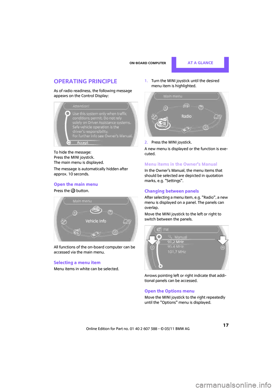
As of radio readiness, the following message
appears on the Control Display:
To hide the message:
Press the MINI joystick.
The main menu is displayed.
The message is automatically hidden after
approx. 10 seconds.
Open the main menu
Press the button.
All functions of the on-board computer can be
accessed via the main menu.
Selecting a menu item
Menu items in white can be selected. 1.
Turn the MINI joystick until the desired
menu item is highlighted.
2. Press the MINI joystick.
A new menu is displayed or the function is exe-
cuted.
Menu items in the Owner's Manual
In the Owner's Manual, the menu items that
should be selected are depicted in quotation
marks, e.g. "Settings".
Changing between panels
After selecting a menu item, e.g. "Radio", a new
menu is displayed on a panel. The panels can
overlap.
Move the MINI joystick to the left or right to
switch between the panels.
Arrows pointing left or right indicate that addi-
tional panels can be accessed.
Open the Options menu
Move the MINI joystick to the right repeatedly
until the "Options" menu is displayed.
Page 29 of 256
Opening and closingCONTROLS
27
>Triple turn signal activation 51
> Settings for the displa ys on the on-board
computer, in the speedometer and in the
tachometer:
> 12 h/24 h mode of the clock 63
> Date format 63
> Brightness of the Control Display 67
> Language on the Control Display 66
> Units of measure for fuel consumption,
distance covered/re maining distances
and temperature 60
> Show visual warning for Park Distance Con-
trol PDC
*68
> Light settings:
>Pathway lighting 81
> Daytime running lights 82
> Automatic climate control: activating/deac-
tivating the AUTO program, setting the tem-
perature, air volume and air distribution 87
> Entertainment:
>Tone control 131
> Adjusting vo lume levels 130
Central lock ing system
The concept
The central locking system is ready for operation
whenever the driver's door is closed.
The system simultaneously engages and
releases the locks on the following:
>Doors
> Split Rear Barn Doors
> Fuel filler flap
Operating from outside
>Via the remote control
> Via the door lock
*
>In cars with Comfort Access*, via the door
handles on the driver's and passenger's
sides
The anti-theft system is also operated at the
same time. It prevents the doors from being
unlocked using the lock buttons or door han-
dles. The remote control can also be used to
switch on/off the welcome lamps and interior
lamps. The alarm system
* is also activated or
deactivated, page 31.
Operating from inside
Button for central locking system, page 30.
In the event of a sufficiently severe accident, the
central locking system unlocks automatically. In
addition, the hazard warning flashers and inte-
rior lamps come on.
Opening and closing:
from outside
Persons or animals in a parked vehicle
could lock the doors from the inside. Take
the key with you when you leave the vehicle so
that the vehicle can be opened from the out-
side. <
Using the remote control
Unlocking
Press the button.
The welcome lamps and interior lamps come on.
Unlocking mode
You can also set which parts of the car are
unlocked. The setting is stored for the remote
control in use.
Page 36 of 256
CONTROLSOpening and closing
34
Unlocking the Split Rear Barn Doors
separately
Press the button on the outside of the Split Rear
Barn Doors.If the vehicle detects that a remote control
has been accidentally left inside the
locked vehicle's cargo area after the Split Rear
Barn Doors are closed, the Split Rear Barn Doors
will reopen slightly. The hazard warning flashers
flash and an acoustic signal
* sounds. <
Windows and glass roof, electric*
If the engine is switched off, you can still operate
the windows and glass roof so long as a door or
the Split Rear Barn Doors have not been opened.
If the doors and Split Rear Barn Doors are closed
again and the remote cont rol is located inside
the vehicle, the windows and the glass roof can
be operated again.
Insert the remote control into the ignition lock to
be able to operate the windows or glass roof
when the engine is switched off and the doors
are open.
Switching on radio readiness
Switch on radio readiness by briefly pressing the
Start/Stop button, page 46.
Do not depress the brake or the clutch;
otherwise, the engine will start. <
Starting the engine
The engine can be started or the ignition can be
switched on when a remote control is inside the
vehicle. It is not necessary to insert a remote
control into the ignition lock, page 46.
Switching off the engine in cars with
automatic transmission
The engine can only be switched off when the
selector lever is in position P, page 48.
To switch the engine off when the selector lever
is in position N, the remote control must be in
the ignition lock.
Before driving a vehicle with automatic
transmission into a car wash
1. Insert remote control into ignition lock.
2. Depress the brake.
3. Move the selector le ver to position N.
4. Switch off the engine.
The vehicle can roll.
Malfunction
Comfort Access may malf unction due to local
radio waves.
If this happens, open or close the vehicle via the
buttons on the remote control or using the inte-
grated key.
Insert the remote control into the ignition lock
and start the engine.
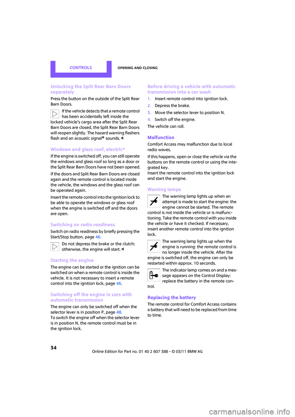
Warning lamps
The warning lamp lights up when an
attempt is made to start the engine: the
engine cannot be started. The remote
control is not inside the vehicle or is malfunc-
tioning. Take the remote control with you inside
the vehicle or have it checked. If necessary,
insert another remote co ntrol into the ignition
lock.
The warning lamp lights up when the
engine is running: the remote control is
no longer inside the vehicle. After the
engine is switched off, the engine can only be
restarted within approx. 10 seconds.
The indicator lamp comes on and a mes-
sage appears on the Control Display:
replace the battery in the remote con-
trol.
Replacing the battery
The remote control for Comfort Access contains
a b a t t e r y t h a t w i l l n e e d t o b e r e p l a c e d f r o m t i m e
to time.
Page 38 of 256
CONTROLSOpening and closing
36
Opening, closing
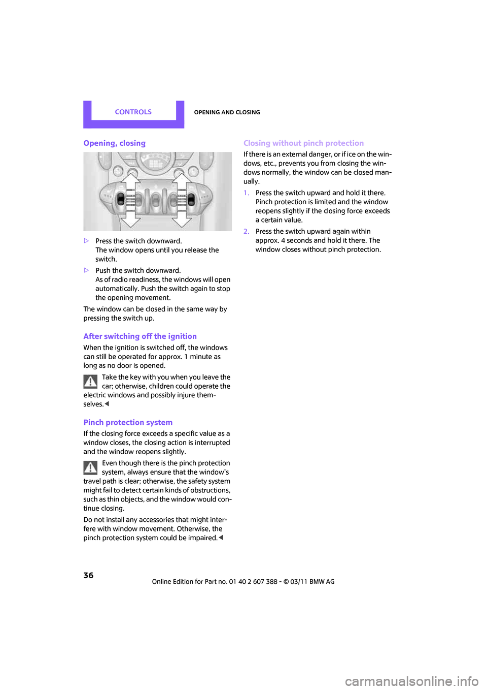
>Press the switch downward.
The window opens until you release the
switch.
> Push the switch downward.
As of radio readiness, the windows will open
automatically. Push the switch again to stop
the opening movement.
The window can be closed in the same way by
pressing the switch up.
After switching off the ignition
When the ignition is switched off, the windows
can still be operated for approx. 1 minute as
long as no door is opened.
Take the key with you when you leave the
car; otherwise, children could operate the
electric windows and possibly injure them-
selves. <
Pinch protection system
If the closing force exceeds a specific value as a
window closes, the closin g action is interrupted
and the window reopens slightly.
Even though there is the pinch protection
system, always ensure that the window's
travel path is clear; otherwise, the safety system
might fail to detect certain kinds of obstructions,
such as thin objects, and the window would con-
tinue closing.
Do not install any accessories that might inter-
fere with window movement. Otherwise, the
pinch protection system could be impaired. <
Closing without pinch protection
If there is an external danger, or if ice on the win-
dows, etc., prevents you from closing the win-
dows normally, the window can be closed man-
ually.
1.Press the switch upward and hold it there.
Pinch protection is limited and the window
reopens slightly if th e closing force exceeds
a certain value.
2. Press the switch upward again within
approx. 4 seconds and hold it there. The
window closes without pinch protection.
Page 40 of 256
CONTROLSAdjustments
38
Seats
Note before adjusting
Never attempt to adjust your seat while
the vehicle is moving. The seat could
respond with unexpected movement, and the
ensuing loss of vehicle control could lead to an
accident.
On the front passenger seat as well, do not
incline the backrest too far to the rear while the
vehicle is being driven; otherwise, there is a dan-
ger in the event of an accident of sliding under
the safety belt, eliminat ing the protection nor-
mally provided by the belt. <
Comply with the instruct ions on head restraint
height on page 39 and on damaged safety belts
on page 41.
Seat adjustment
Observe the instructions on page 38 to
ensure the best possible personal protec-
tion. <
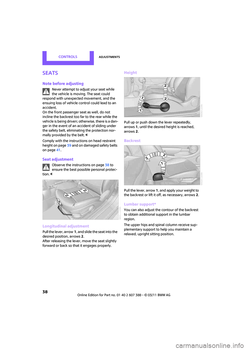
Longitudinal adjustment
Pull the lever, arrow 1, and slide the seat into the
desired position, arrows 2.
After releasing the lever, move the seat slightly
forward or back so that it engages properly.
Height
Pull up or push down the lever repeatedly,
arrows 1, until the desired he ight is reached,
arrows 2.
Backrest
Pull the lever, arrow 1, and apply your weight to
the backrest or lift it off, as necessary, arrows 2.
Lumbar support*
You can also adjust the contour of the backrest
to obtain additional support in the lumbar
region.
The upper hips and spinal column receive sup-
plementary support to help you maintain a
relaxed, upright sitting position.