low beam MINI Clubman 2011 Owner's Manual (Mini Connected)
[x] Cancel search | Manufacturer: MINI, Model Year: 2011, Model line: Clubman, Model: MINI Clubman 2011Pages: 256, PDF Size: 3.75 MB
Page 12 of 256
AT A GLANCECockpit
10
Cockpit
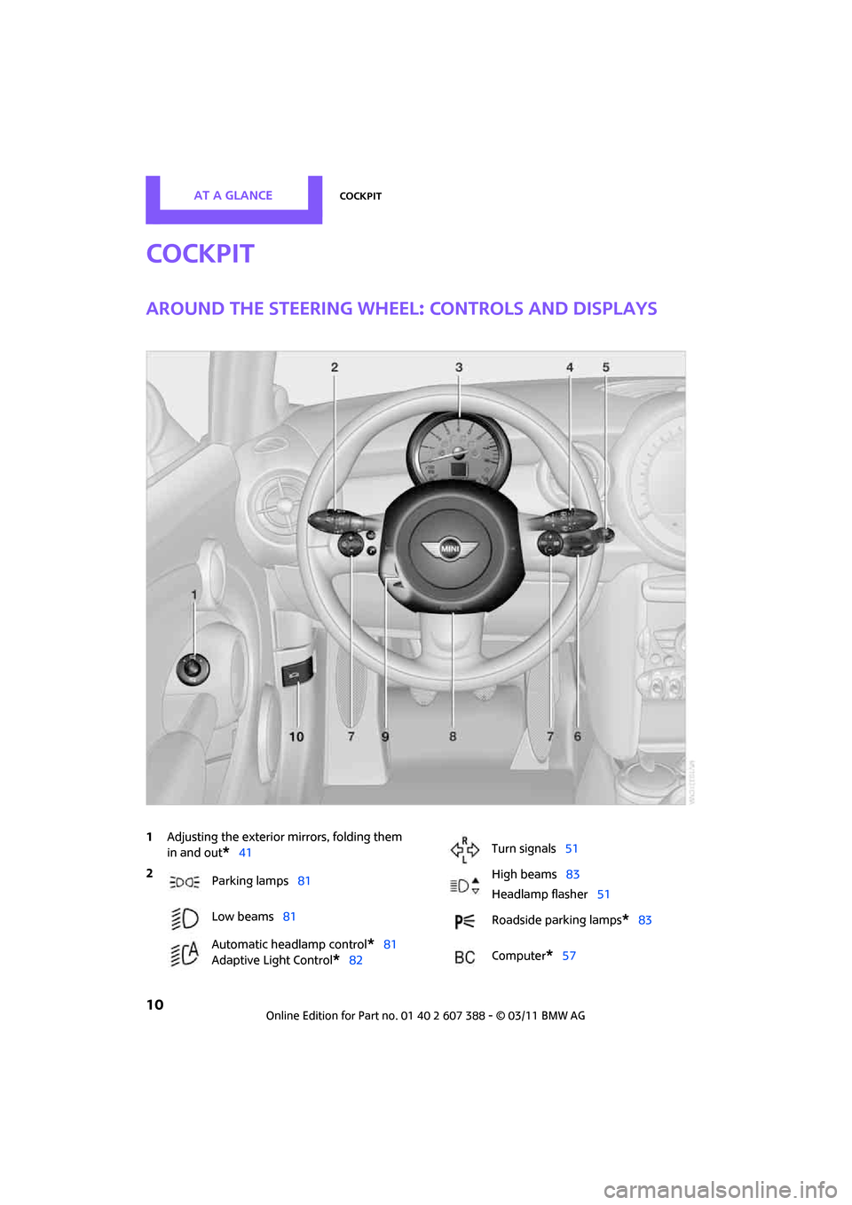
Around the steering wheel: controls and displays
1Adjusting the exterior mirrors, folding them
in and out
*41
2
Parking lamps 81
Low beams 81
Automatic headlamp control
*81
Adaptive Light Control
*82
Turn signals 51
High beams 83
Headlamp flasher 51
Roadside parking lamps
*83
Computer
*57
Page 15 of 256
CockpitAT A GLANCE
13
Indicator and warning
lamps
The concept
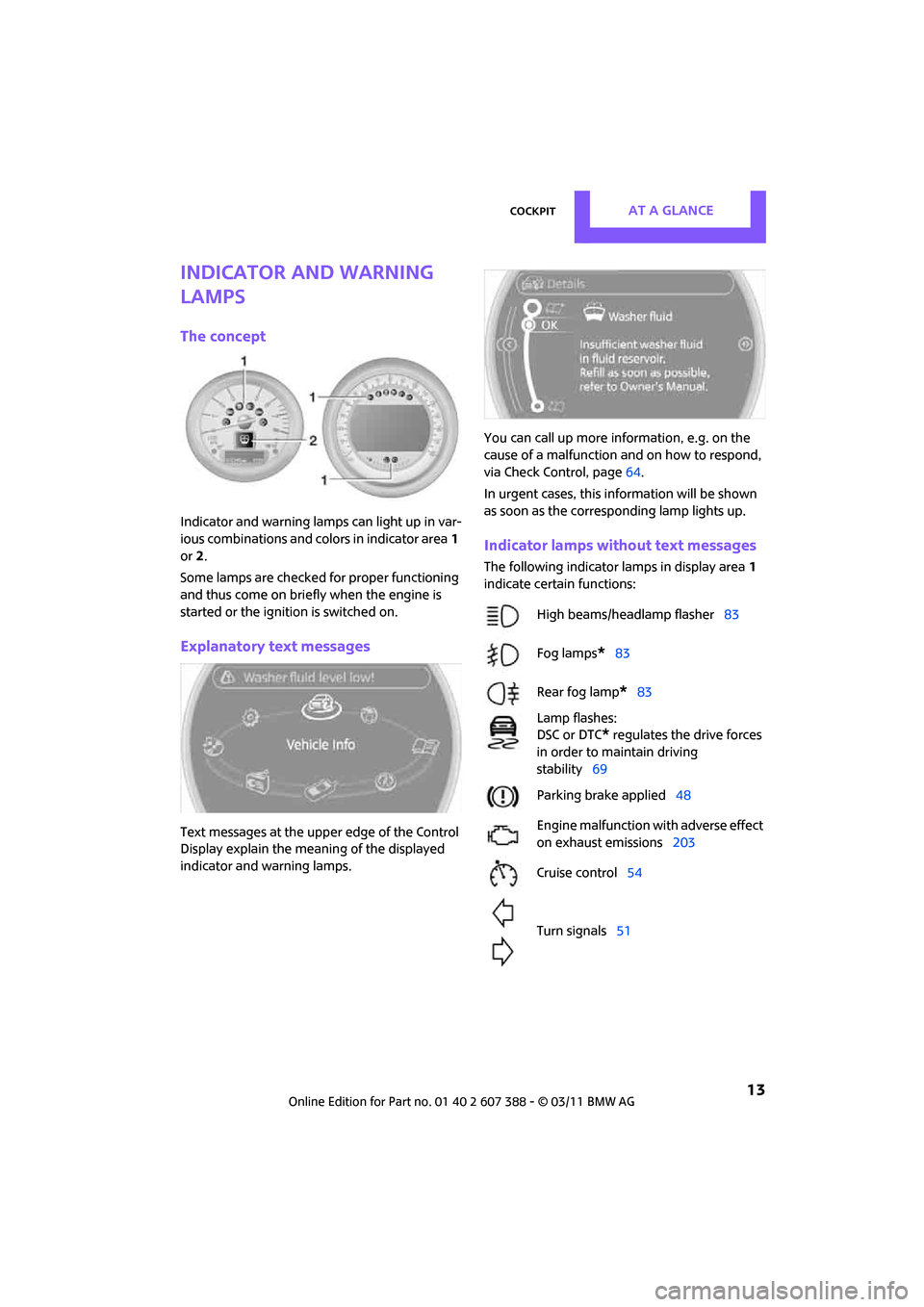
Indicator and warning lamps can light up in var-
ious combinations and colors in indicator area1
or 2.
Some lamps are checked for proper functioning
and thus come on briefly when the engine is
started or the ignition is switched on.
Explanatory text messages
Text messages at the uppe r edge of the Control
Display explain the mean ing of the displayed
indicator and warning lamps. You can call up more information, e.g. on the
cause of a malfunction and on how to respond,
via Check Control, page
64.
In urgent cases, this information will be shown
as soon as the corresponding lamp lights up.
Indicator lamps without text messages
The following indicator lamps in display area 1
indicate certain functions:
High beams/headlamp flasher 83
Fog lamps
*83
Rear fog lamp
*83
Lamp flashes:
DSC or DTC
* regulates the drive forces
in order to maintain driving
stability 69
Parking brake applied 48
Engine malfunction with adverse effect
on exhaust emissions 203
Cruise control 54
Turn signals 51
Page 49 of 256
DrivingCONTROLS
47
Radio readiness and ignition off
All indicator and warning lamps in the displays
go out.
The ignition automatically turns off
* when the
driver's door is opened. Pressing the Start/Stop
button again switches the ignition back on.
The ignition is not switched off in situations such
as the following:
> The clutch or brake is depressed
> The low beams are switched on
Starting the engine
Do not allow the engine to run in enclosed
areas; otherwise, inhalation of the noxious
exhaust gases can lead to loss of consciousness
and death. Exhaust gases contain carbon mon-
oxide, an odorless and colorless, but highly toxic
gas. Never leave an unattended vehicle with the
engine running; otherwise, such a vehicle repre-
sents a potential safety hazard.
Before leaving the car while the engine is run-
ning, place the transmission in neutral or move
the selector lever to position P and forcefully
apply the parking brake to prevent the car from
moving. <
Avoid frequent starting in quick succes-
sion or repeated start attempts in which
the engine does not start. Otherwise, the fuel is
not burned or inadequately burned and there is
a danger of overheating and damaging the cat-
alytic converter. <
Do not let the engine warm up with the vehicle
at a standstill. Move of f immediately at a moder-
ate engine speed.
When starting the engine, do not depress the
accelerator pedal.
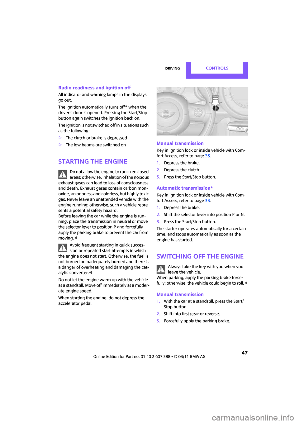
Manual transmission
Key in ignition lock or inside vehicle with Com-
fort Access, refer to page 33.
1. Depress the brake.
2. Depress the clutch.
3. Press the Start/Stop button.
Automatic transmission*
Key in ignition lock or inside vehicle with Com-
fort Access, refer to page 33.
1. Depress the brake.
2. Shift the selector lever into position P or N.
3. Press the Start/Stop button.
The starter operates auto matically for a certain
time, and stops automatically as soon as the
engine has started.
Switching off the engine
Always take the key with you when you
leave the vehicle.
When parking, apply the parking brake force-
fully; otherwise, the vehicle could begin to roll. <
Manual transmission
1.With the car at a standstill, press the Start/
Stop button.
2. Shift into first gear or reverse.
3. Forcefully apply the parking brake.
Page 69 of 256
Controls overviewCONTROLS
67
Setting the voice dialog
Switch between a standard dialog and a short
dialog.
1."Settings"
2. "Language/Units"
3. "Speech mode:"
4. Select the desired dialog.
The setting is stored for the remote control cur-
rently in use.
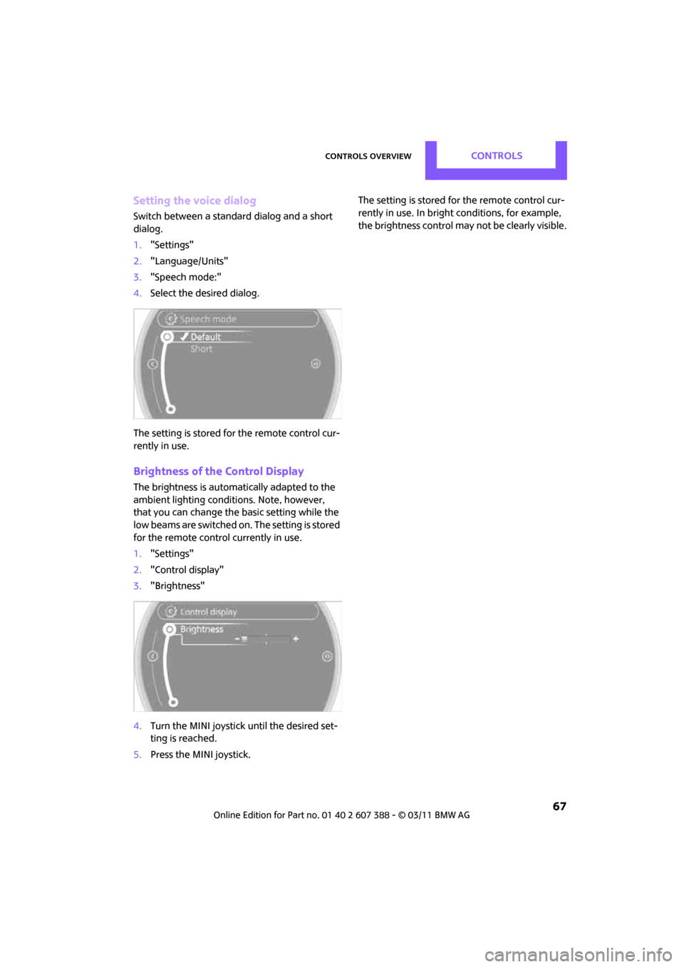
Brightness of the Control Display
The brightness is automatically adapted to the
ambient lighting conditions. Note, however,
that you can change the basic setting while the
low beams are switched on . The setting is stored
for the remote control currently in use.
1. "Settings"
2. "Control display"
3. "Brightness"
4. Turn the MINI joystick until the desired set-
ting is reached.
5. Press the MINI joystick. The setting is stored for the remote control cur-
rently in use. In bright
conditions, for example,
the brightness control may not be clearly visible.
Page 83 of 256
LampsCONTROLS
81
Lamps
Parking lamps/low beams
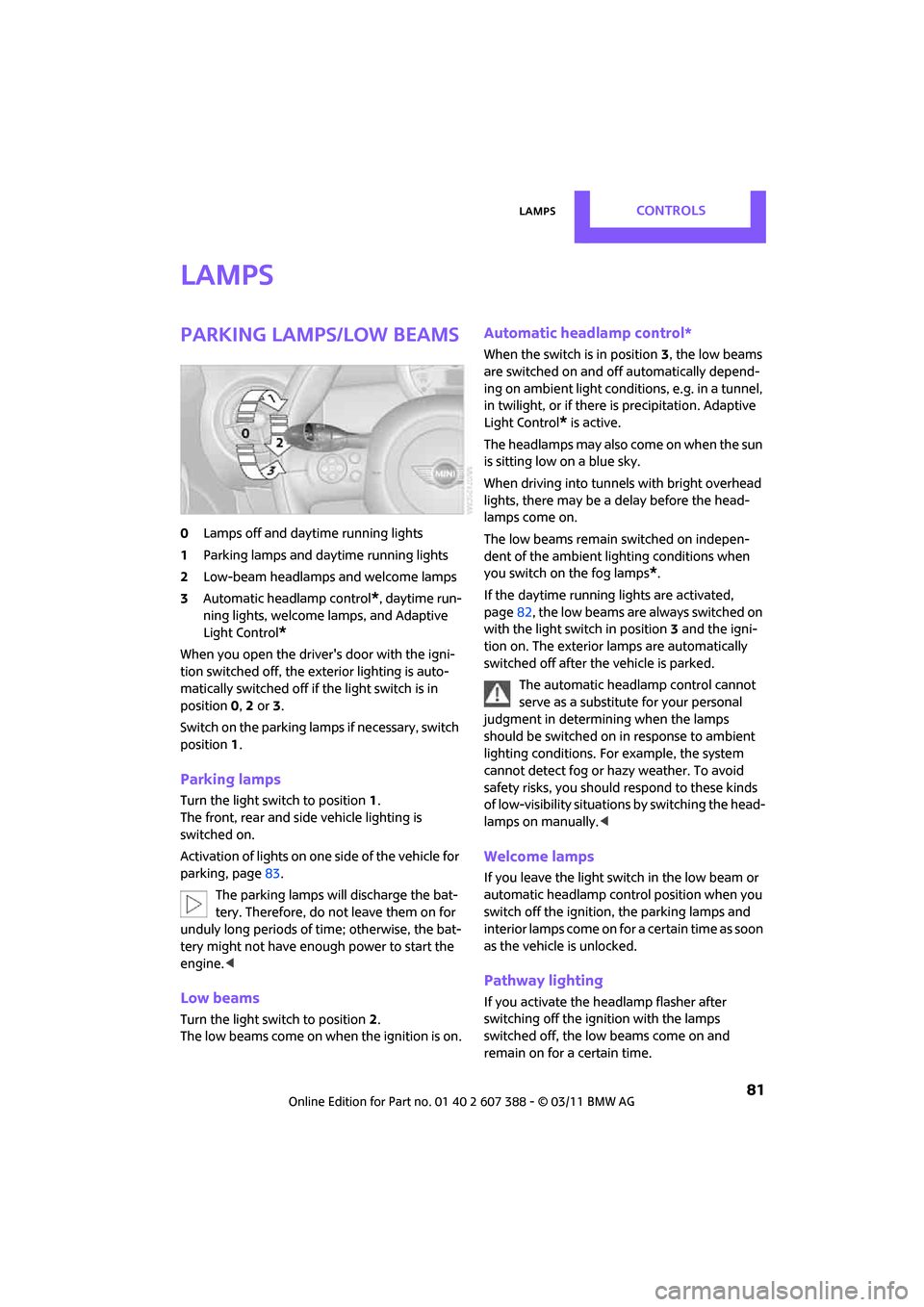
0Lamps off and daytime running lights
1 Parking lamps and daytime running lights
2 Low-beam headlamps and welcome lamps
3 Automatic headlamp control
*, daytime run-
ning lights, welcome lamps, and Adaptive
Light Control
*
When you open the driver's door with the igni-
tion switched off, the exterior lighting is auto-
matically switched off if the light switch is in
position 0, 2 or 3.
Switch on the parking lamps if necessary, switch
position 1.
Parking lamps
Turn the light switch to position 1.
The front, rear and side vehicle lighting is
switched on.
Activation of lights on one side of the vehicle for
parking, page 83.
The parking lamps will discharge the bat-
tery. Therefore, do not leave them on for
unduly long periods of time; otherwise, the bat-
tery might not have enough power to start the
engine. <
Low beams
Turn the light switch to position 2.
The low beams come on when the ignition is on.
Automatic headlamp control*
When the switch is in position 3, the low beams
are switched on and of f automatically depend-
ing on ambient light condit ions, e.g. in a tunnel,
in twilight, or if there is precipitation. Adaptive
Light Control
* is active.
The headlamps may also come on when the sun
is sitting low on a blue sky.
When driving into tunnels with bright overhead
lights, there may be a delay before the head-
lamps come on.
The low beams remain switched on indepen-
dent of the ambient lighting conditions when
you switch on the fog lamps
*.
If the daytime running lights are activated,
page 82, the low beams are al ways switched on
with the light switch in position 3 and the igni-
tion on. The exterior lamps are automatically
switched off after the vehicle is parked.
The automatic headlamp control cannot
serve as a substitute for your personal
judgment in determin ing when the lamps
should be switched on in response to ambient
lighting conditions. For example, the system
cannot detect fog or hazy weather. To avoid
safety risks, you should respond to these kinds
of low-visibility situations by switching the head-
lamps on manually. <
Welcome lamps
If you leave the light switch in the low beam or
automatic headlamp control position when you
switch off the ignition, the parking lamps and
interior lamps come on fo r a certain time as soon
as the vehicle is unlocked.
Pathway lighting
If you activate the headlamp flasher after
switching off the ignition with the lamps
switched off, the lo w beams come on and
remain on for a certain time.
Page 85 of 256
LampsCONTROLS
83
High beams/
roadside parking lamps
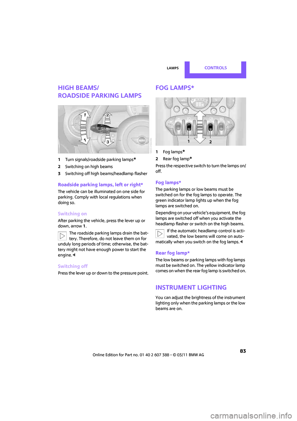
1Turn signals/roadside parking lamps*
2Switching on high beams
3 Switching off high be ams/headlamp flasher
Roadside parking lamps, left or right*
The vehicle can be illumi nated on one side for
parking. Comply with local regulations when
doing so.
Switching on
After parking the vehicle, press the lever up or
down, arrow 1.
The roadside parking lamps drain the bat-
tery. Therefore, do not leave them on for
unduly long periods of time; otherwise, the bat-
tery might not have enough power to start the
engine. <
Switching off
Press the lever up or down to the pressure point.
Fog lamps*
1Fog lamps*
2Rear fog lamp*
Press the respective switch to turn the lamps on/
off.
Fog lamps*
The parking lamps or low beams must be
switched on for the fog lamps to operate. The
green indicator lamp lights up when the fog
lamps are switched on.
Depending on your vehicle's equipment, the fog
lamps are switched off when you activate the
headlamp flasher or switch on the high beams.
If the automatic headlamp control is acti-
vated, the low beams will come on auto-
matically when you switch on the fog lamps. <
Rear fog lamp*
The low beams or parking lamps with fog lamps
must be switched on. The yellow indicator lamp
comes on when the rear fog lamp is switched on.
Instrument lighting
You can adjust the brightness of the instrument
lighting only when the parking lamps or the low
beams are on.
Page 212 of 256
MOBILITYReplacing components
210
Xenon lamps*
The service life of these bulbs is very long and
the probability of failure very low, provided that
they are not switched on and off an excessive
number of times. If a xenon lamp fails neverthe-
less, switch on the fog lamps and continue the
journey with great care, provided that local leg-
islation does not prohibit this.
Have any work on the xenon lamp system,
including bulb replacement, carried out
only by a MINI dealer or a workshop that has
specially trained personnel working in accor-
dance with the specifications of the MINI manu-
facturer. Due to high voltage, there is a risk of
fatal injury if work on the xenon lamps is carried
out improperly.<
Halogen low beams and high beams
H13 bulb, 60/55 watts
The H13 bulb is pressurized. Therefore,
wear safety glasses and protective gloves.
Otherwise, there is a risk of injury if the bulb is
damaged. <
Be careful when insta lling the cover; oth-
erwise, leaks could occur and cause dam-
age to the headlamp system. <
Accessing the lamp from the engine
compartment
The low-beam/high-beam bulb can be changed
from the engine compartment.
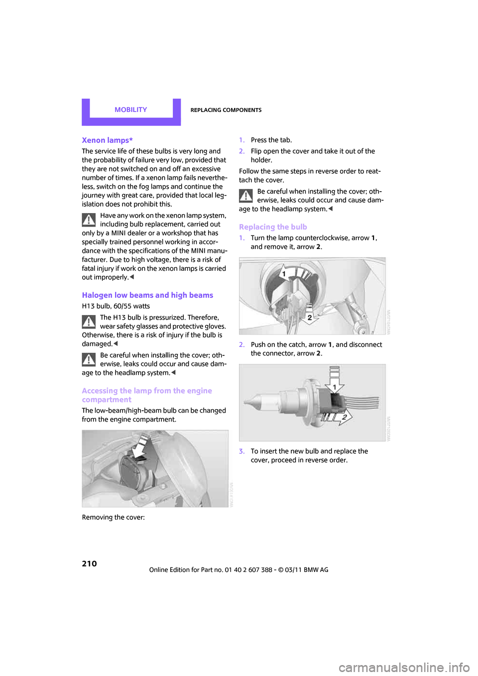
Removing the cover: 1.
Press the tab.
2. Flip open the cover and take it out of the
holder.
Follow the same steps in reverse order to reat-
tach the cover. Be careful when insta lling the cover; oth-
erwise, leaks could occur and cause dam-
age to the headlamp system. <
Replacing the bulb
1.Turn the lamp counterclockwise, arrow 1,
and remove it, arrow 2.
2. Push on the catch, arrow 1, and disconnect
the connector, arrow 2.
3. To insert the new bulb and replace the
cover, proceed in reverse order.
Page 223 of 256
Giving and receiving assistanceMOBILITY
221
Using a tow fitting
The screw-in tow fitting must always be carried
in the car. It can be screwed in at the front or
rear of the MINI.
It is stored in the onboard vehicle toolkit in the
cargo area underneath the cover on the right-
hand side, page 208.
Use only the tow fitting provided with the
vehicle and screw it all the way in. Use the
tow fitting for towing on paved roads only. Avoid
lateral loading of the tow fitting, e.g. do not lift
the vehicle by the tow fitting. Otherwise, the tow
fitting and the vehicle could be damaged. <
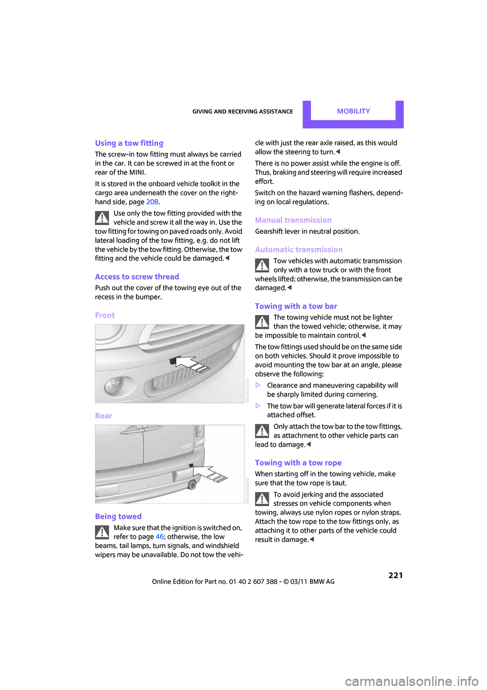
Access to screw thread
Push out the cover of the towing eye out of the
recess in the bumper.
Front
Rear
Being towed
M a k e s u r e t h a t t h e i g n i t i o n i s s w i t c h e d o n ,
refer to page46; otherwise, the low
beams, tail lamps, turn signals, and windshield
wipers may be unavailable. Do not tow the vehi- cle with just the rear ax
le raised, as this would
allow the steering to turn. <
There is no power assist while the engine is off.
Thus, braking and steering will require increased
effort.
Switch on the hazard warning flashers, depend-
ing on local regulations.
Manual transmission
Gearshift lever in neutral position.
Automatic transmission
Tow vehicles with automatic transmission
only with a tow truck or with the front
wheels lifted; otherwise, the transmission can be
damaged. <
Towing with a tow bar
The towing vehicle must not be lighter
than the towed vehicle; otherwise, it may
be impossible to maintain control. <
The tow fittings used should be on the same side
on both vehicles. Should it prove impossible to
avoid mounting the tow bar at an angle, please
observe the following:
> Clearance and maneuvering capability will
be sharply limited during cornering.
> The tow bar will generate lateral forces if it is
attached offset.
Only attach the tow bar to the tow fittings,
as attachment to ot her vehicle parts can
lead to damage. <
Towing with a tow rope
When starting off in the towing vehicle, make
sure that the tow rope is taut.
To avoid jerking and the associated
stresses on vehicle components when
towing, always use nylon ropes or nylon straps.
Attach the tow rope to the tow fittings only, as
attaching it to other parts of the vehicle could
result in damage. <
Page 243 of 256
Everything from A to ZREFERENCE
241
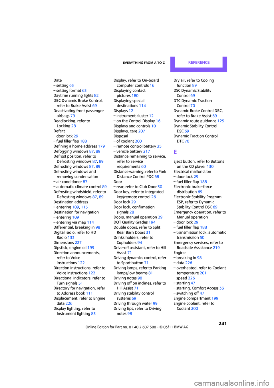
Date
– setting63
– setting format 63
Daytime running lights 82
DBC Dynamic Brake Control, refer to Brake Assist 69
Deactivating front passenger
airbags 79
Deadlocking, refer to Locking 28
Defect
– door lock 29
– fuel filler flap 188
Defining a home address 179
Defogging windows 87,89
Defrost position, refer to
Defrosting windows 87,89
Defrosting windows 87,89
Defrosting windows and
removing condensation
– air conditioner 87
– automatic climate control 89
Defrosting windshield, refer to Defrosting windows 87,89
Destination address
– entering 109,115
Destination for navigation
– entering 109
– entering via map 114
Differential, breaking in 98
Digital radio, refer to HD Radio 133
Dimensions 227
Dipstick, engine oil 199
Direction announcements, refer to Voice
instructions 122
Direction instructions, refer to Voice instructions 122
Directional indicators, refer to Turn signals 51
Directory for navigation, refer
to Address book 111
Displacement, refer to Engine data 226
Display lighting, refer to Instrument lighting 83Display, refer to On-board
computer controls 16
Displaying contact pictures 180
Displaying special destinations 114
Displays 12
– instrument cluster 12
– on the Control Display 16
Displays and controls 10
Displays, care 207
Disp
osal
– of coolant 200
– remote control battery 35
– vehicle battery 217
Distance remaining to service,
refer to Service
requirements 60
Distance warning, refer to Park
Distance Control PDC 68
Door
– rear, refer to Club Door 30
Door key, refer to Integrated key/remote control 26
Door lock 29
Door lock, confirmation signals 28
Doors, manual operation 29
DOT Quality Grades 194
Double doors, refer to Split
Rear Barn Doors 31
Drinks holders, refer to Cupholders 94
Drive-off assistant, refer to Hill
Assist 71
Driving dynamics control, refer
to Sport button 71
Driving lamps, refer to Parking lamps/low beams 81
Driving notes 98
Driving off on inclines, refer to Hill Assist 71
Driving stability control systems 69
Driving through water 99
Driving tips, refer to Driving notes 98 Dry air, refer to Cooling
function 89
DSC Dynamic Stability Control 69
DTC Dynamic Traction Control 70
Dynamic Brake Control DBC,
refer to Brake Assist 69
Dynamic route guidance 125
Dynamic Stability Control
DSC 69
Dynamic Traction Control DTC 70
E
Eject button, refer to Buttons
on the CD player 130
Electrical malfunction
– door lock 29
– fuel filler flap 188
Electronic brake-force
distribution 69
Electronic Stability Program ESP, refer to Dynamic
Stability Control DSC 69
Emergency operation, refer to Manual operation
– door lock 29
– fuel filler flap 188
– transmission lock, automatic transmission 50
Emergency services, refer to
Roadside Assistance 219
Engine
– breaking in 98
– data 226
– overheated, refer to Coolant temperature 201
– speed 226
– starting 47
– starting, Comfort Access 33
– switching off 47
Engine compartment 199
Engine coolant, refer to
Coolant 200
Page 246 of 256
REFERENCEEverything from A to Z
244
Internet page4
J
Jacking points 216
Jets, refer to Window washer nozzles 53
Joystick, refer to On-board computer 16
Jumpering, refer to Jump-
starting 219
Jump-starting 219
K
Key Memory, refer to Personal
Profile 26
Key, refer to Keys/remote controls 26
Keyless opening and closing, refer to Comfort Access 33
Keyless-Go, refer to Comfort
Access 33
Keypad dialing 159,171
Kickdown 49
– automatic transmission with Steptronic 49
Knock control 189
L
Lamps and bulbs, replacing
bulbs 209
Lamps, refer to Parking lamps/ Low beams 81
Lashing eyes, refer to Securing
cargo 103
Last destinations 112
LATCH child restraint fixing
system 44
Leather care 206
LEDs light-emitting diodes 209
Length, refer to Dimensions 227
License plate lamp
– bulb replacement 213Liftgate
– Comfort Access
34
Liftgate, refer to Split Rear Barn Doors 28
Light alloy wheels, care 206
Light switch 81
Light-emitting diodes
LEDs 209
Lighter 94
– socket 94
Lighting
– lamps and bulbs 209
– of the instruments 83
– of vehicle, refer to Lamps 81
Limit, refer to Speed limit 65
Load 102
Load securing equipment, refer to Securing cargo 103
Lock buttons of doors, refer to
Locking 30
Locking
– adjusting confirmation
signal 28
– from inside 30
– from outside 28
– without remote control, refer
to Comfort Access 33
Locking and unlocking doors
– confirmation signals 28
– from inside 30
– from outside 27
Longlife oils
– approved motor oils 200
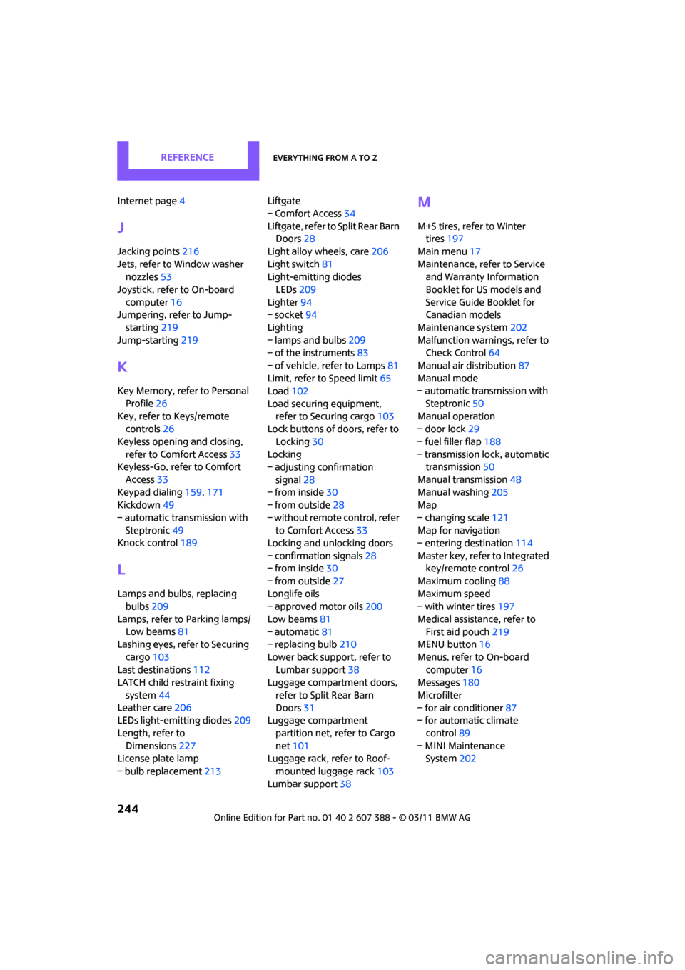
Low beams 81
– automatic 81
– replacing bulb 210
Lower back support, refer to Lumbar support 38
Luggage compartment doors,
refer to Split Rear Barn
Doors 31
Luggage compartment
partition net, refer to Cargo
net 101
Luggage rack, refer to Roof-
mounted luggage rack 103
Lumbar support 38
M
M+S tires, refer to Winter
tires 197
Main menu 17
Maintenance, refer to Service and Warranty Information
Booklet for US models and
Service Guide Booklet for
Canadian models
Maintenance system 202
Malfunction warnings, refer to Check Control 64
Manual air distribution 87
Manual mode
– automatic transmission with
Steptronic 50
Manual operation
– door lock 29
– fuel filler flap 188
– transmission lock, automatic transmission 50
Manual transmission 48
Manual washing 205
Map
– changing scale 121
Map for navigation
– entering destination 114
Master key, refer to Integrated key/remote control 26
Maximum cooling 88
Maximum speed
– with winter tires 197
Medical assistance, refer to First aid pouch 219
MENU button 16
Menus, refer to On-board computer 16
Messages 180
Microfilter
– for air conditioner 87
– for automatic climate
control 89
– MINI Maintenance System 202