tow MINI Clubman 2012 User Guide
[x] Cancel search | Manufacturer: MINI, Model Year: 2012, Model line: Clubman, Model: MINI Clubman 2012Pages: 207, PDF Size: 3.26 MB
Page 99 of 207
DRIVING TIPSThings to remember when driving
98
MINI Clubman: cargo net
Ensure that the cargo net is firmly
attached; otherwise, injuries may occur.<
The cargo net can be mounted in the cargo area
or behind the front seats.
In the cargo area
1. Fold the rear seat backrest forward if neces-
sary, page 97.
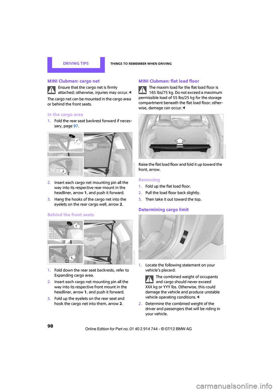
2. Insert each cargo net mounting pin all the
way into its respective rear mount in the
headliner, arrow 1, and push it forward.
3. Hang the hooks of the cargo net into the
eyelets on the rear cargo well, arrow2.
Behind the front seats
1. Fold down the rear seat backrests, refer to
Expanding cargo area.
2. Insert each cargo net mounting pin all the
way into its respective front mount in the
headliner, arrow 1, and push it forward.
3. Fold up the eyelets on the rear seat and
hook the cargo net into them, arrow 2.
MINI Clubman: flat load floor
The maxim load for the flat load floor is
165 lbs/75 kg. Do not exceed a maximum
permissible load of 55 lbs/25 kg for the storage
compartment beneath the flat load floor; other-
wise, damage can occur. <
Raise the flat load floor an d fold it up toward the
front, arrow.
Removing
1. Fold up the flat load floor.
2. Pull the load floor back slightly.
3. Then take it out toward the top.
Determining cargo limit
1.Locate the following statement on your
vehicle's placard:
The combined weight of occupants
and cargo should never exceed
XXX kg or YYY lbs. Otherwise, this could
damage the vehicle and produce unstable
vehicle operating conditions. <
2. Determine the combined weight of the
driver and passengers that will be riding in
your vehicle.
Online Edition for Part no. 01 40 2 914 744 - \251 07/12 BMW AG
Page 100 of 207
Things to remember when drivingDRIVING TIPS
99
3.Subtract the combined weight of the driver
and passengers from XXX pounds or YYY
kilograms.
4. The resulting figure equals the available
amount of cargo and luggage load capacity.
For example, if the XXX amount equals
1,400 lbs and there will be four 150 lbs
passengers in your vehicle, the amount of
available cargo and luggage load capacity is
650 lbs:
1,400 lbs minus 750 lbs = 650 lbs.
5. Determine the combined weight of luggage
and cargo being loaded on the vehicle. That
weight may not safely exceed the available
cargo and luggage load capacity calculated
in step 4.
6. If your vehicle will be towing a trailer, part of
the load from your trail er will be transferred
to your vehicle. Consult the manual for
transporting a trailer to determine how this
may reduce the available cargo and luggage
load capacity of your vehicle.
Load
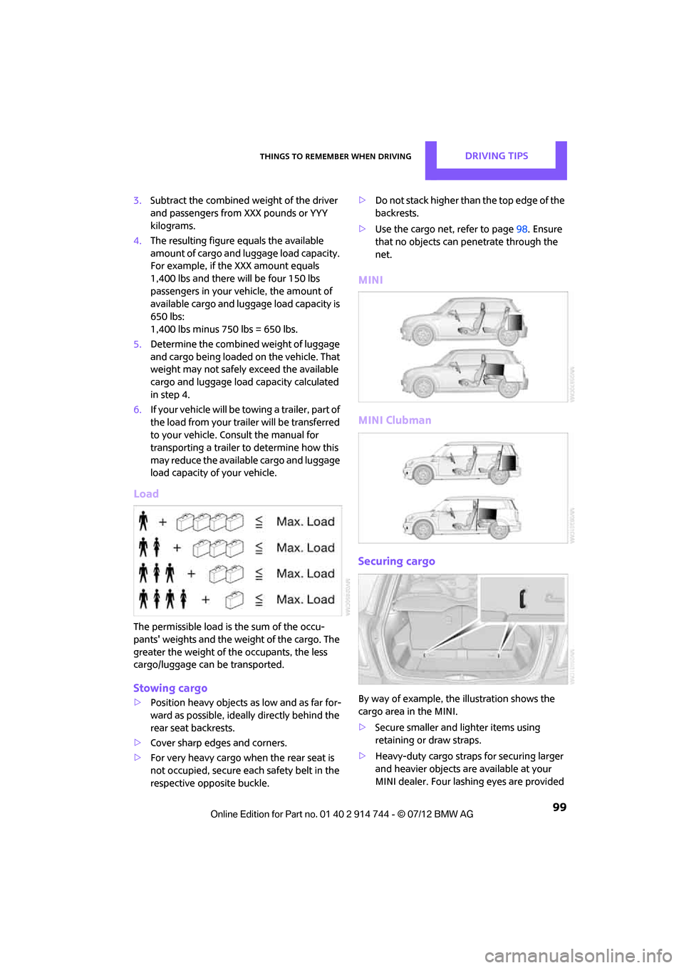
The permissible load is the sum of the occu-
pants' weights and the weight of the cargo. The
greater the weight of the occupants, the less
cargo/luggage can be transported.
Stowing cargo
> Position heavy objects as low and as far for-
ward as possible, ideally directly behind the
rear seat backrests.
> Cover sharp edges and corners.
> For very heavy cargo when the rear seat is
not occupied, secure each safety belt in the
respective opposite buckle. >
Do not stack higher than the top edge of the
backrests.
> Use the cargo net, refer to page 98. Ensure
that no objects can penetrate through the
net.
MINI
MINI Clubman
Securing cargo
By way of example, the illustration shows the
cargo area in the MINI.
> Secure smaller and lighter items using
retaining or draw straps.
> Heavy-duty cargo straps for securing larger
and heavier objects ar e available at your
MINI dealer. Four lashing eyes are provided
Online Edition for Part no. 01 40 2 914 744 - \251 07/12 BMW AG
Page 126 of 207

TelephoneCOMMUNICATIONS
125
General information
Detailed information on snap-in adapters that
compatibly support mobile phone functions can
be found at your MINI dealer.
Do not expose your mobile phone to extreme
ambient conditions, for ex ample, very high tem-
peratures; otherwise, functions on your mobile
phone may not work. Follow the operating
instructions for your mobile phone.
Installation location
In the center armrest.
Inserting snap-in adapter
1. Press the button an d remove the cover.
2. Insert the snap-in adapter at the front,
arrow 1, and press downward, arrow 2, until
it clicks into place.
Inserting mobile phone
1. Depending on the mobile phone, it may be
necessary to remove the protective cap of
the antenna connector and from the USB
connection of the mobile phone.
2. Push the mobile phone with the buttons
facing upward toward the electrical connec-
tions and press down until it engages.
Removing mobile phone
Press the button and remove the mobile phone.
Online Edition for Part no. 01 40 2 914 744 - \251 07/12 BMW AG
Page 141 of 207
MOBILITYWheels and tires
140
Winter tires
When winter tires wear down past a tread depth
of 0.16 in/4 mm, they become perceptibly less
suitable for winter conditions. In the interest of
safety, new tires should be installed.
Minimum tread depth
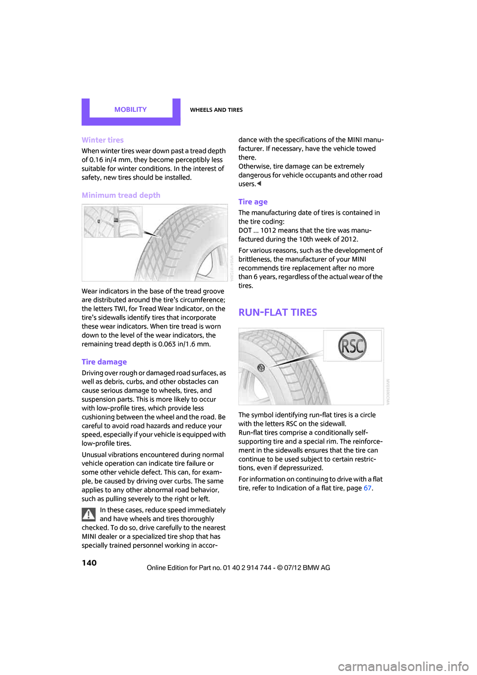
Wear indicators in the base of the tread groove
are distributed around the tire's circumference;
the letters TWI, for Tread Wear Indicator, on the
tire's sidewalls identify tires that incorporate
these wear indicators. When tire tread is worn
down to the level of the wear indicators, the
remaining tread dept h is 0.063 in/1.6 mm.
Tire damage
Driving over rough or damaged road surfaces, as
well as debris, curbs, and other obstacles can
cause serious damage to wheels, tires, and
suspension parts. This is more likely to occur
with low-profile tire s, which provide less
cushioning between the wheel and the road. Be
careful to avoid road hazards and reduce your
speed, especially if your vehicle is equipped with
low-profile tires.
Unusual vibrations encountered during normal
vehicle operation can indicate tire failure or
some other vehicle defect . This can, for exam-
ple, be caused by drivin g over curbs. The same
applies to any other abnormal road behavior,
such as pulling severely to the right or left.
In these cases, reduce speed immediately
and have wheels and tires thoroughly
checked. To do so, drive carefully to the nearest
MINI dealer or a specialized tire shop that has
specially trained personnel working in accor- dance with the specifications of the MINI manu-
facturer. If necessary, have the vehicle towed
there.
Otherwise, tire damage can be extremely
dangerous for vehicle occupants and other road
users.
<
Tire age
The manufacturing date of tires is contained in
the tire coding:
DOT ... 1012 means that the tire was manu-
factured during the 10th week of 2012.
For various reasons, such as the development of
brittleness, the manufacturer of your MINI
recommends tire replac ement after no more
than 6 years, regardless of the actual wear of the
tires.
Run-flat tires
The symbol identifying run-flat tires is a circle
with the letters RSC on the sidewall.
Run-flat tires comprise a conditionally self-
supporting tire and a spec ial rim. The reinforce-
ment in the sidewalls ensures that the tire can
continue to be used subject to certain restric-
tions, even if depressurized.
For information on continuing to drive with a flat
tire, refer to Indication of a flat tire, page 67.
Online Edition for Part no. 01 40 2 914 744 - \251 07/12 BMW AG
Page 145 of 207
MOBILITYEngine compartment
144
Hood
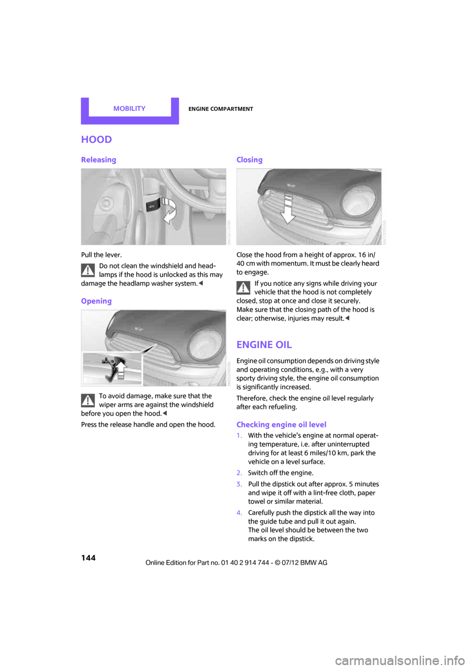
Releasing
Pull the lever.Do not clean the windshield and head-
lamps if the hood is unlocked as this may
damage the headlamp washer system. <
Opening
To avoid damage, make sure that the
wiper arms are against the windshield
before you open the hood. <
Press the release handle and open the hood.
Closing
Close the hood from a height of approx. 16 in/
40 cm with momentum. It must be clearly heard
to engage.
If you notice any signs while driving your
vehicle that the hood is not completely
closed, stop at once and close it securely.
Make sure that the closing path of the hood is
clear; otherwise, injuries may result. <
Engine oil
Engine oil consumption depends on driving style
and operating conditions, e.g., with a very
sporty driving style, the engine oil consumption
is significantly increased.
Therefore, check the engine oil level regularly
after each refueling.
Checking engine oil level
1. With the vehicle's engine at normal operat-
ing temperature, i.e. after uninterrupted
driving for at least 6 miles/10 km, park the
vehicle on a level surface.
2. Switch off the engine.
3. Pull the dipstick out after approx. 5 minutes
and wipe it off with a lint-free cloth, paper
towel or similar material.
4. Carefully push the dipstick all the way into
the guide tube and pull it out again.
The oil level should be between the two
marks on the dipstick.
Online Edition for Part no. 01 40 2 914 744 - \251 07/12 BMW AG
Page 154 of 207
Replacing componentsMOBILITY
153
Replacing components
Vehicle equipment
In this chapter, all production, country, and
optional equipment that is offered in the model
range is described. Equipment is also described
that is not available because of, for example,
selected options or count ry version. This also
applies to safety related functions and systems.
Toolkit
Your vehicle comes with a toolkit that varies
with the equipment version; it is stored under-
neath the flat load floor.
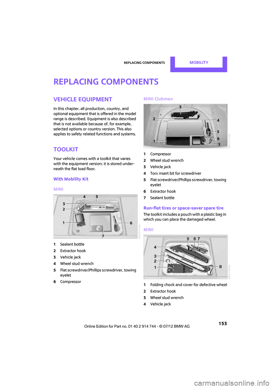
With Mobility Kit
MINI
1 Sealant bottle
2 Extractor hook
3 Vehicle jack
4 Wheel stud wrench
5 Flat screwdriver/Phillips screwdriver, towing
eyelet
6 Compressor
MINI Clubman
1Compressor
2 Wheel stud wrench
3 Vehicle jack
4 Torx insert bit for screwdriver
5 Flat screwdriver/Phillips screwdriver, towing
eyelet
6 Extractor hook
7 Sealant bottle
Run-flat tires or space-saver spare tire
The toolkit includes a pouch with a plastic bag in
which you can place the damaged wheel.
MINI
1Folding chock and cove r for defective wheel
2 Extractor hook
3 Wheel stud wrench
4 Vehicle jack
Online Edition for Part no. 01 40 2 914 744 - \251 07/12 BMW AG
Page 155 of 207
MOBILITYReplacing components
154
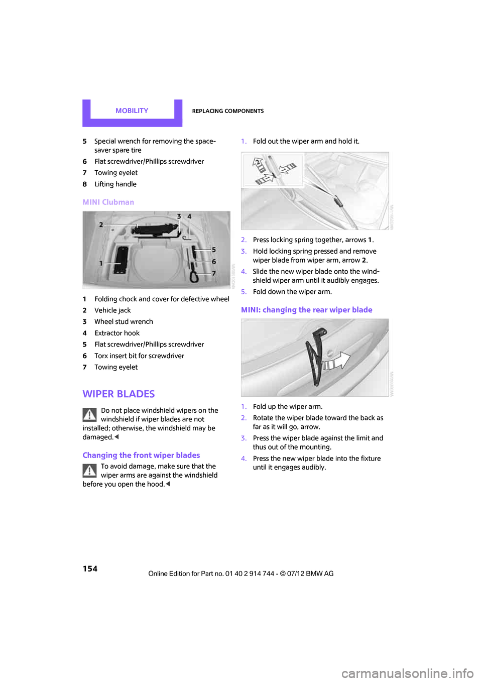
5Special wrench for removing the space-
saver spare tire
6 Flat screwdriver/Phillips screwdriver
7 Towing eyelet
8 Lifting handle
MINI Clubman
1Folding chock and cover for defective wheel
2 Vehicle jack
3 Wheel stud wrench
4 Extractor hook
5 Flat screwdriver/Phillips screwdriver
6 Torx insert bit for screwdriver
7 Towing eyelet
Wiper blades
Do not place windshield wipers on the
windshield if wiper blades are not
installed; otherwise, the windshield may be
damaged. <
Changing the front wiper blades
To avoid damage, make sure that the
wiper arms are against the windshield
before you open the hood. <1.
Fold out the wiper arm and hold it.
2. Press locking spring together, arrows1.
3. Hold locking spring pressed and remove
wiper blade from wiper arm, arrow 2.
4. Slide the new wiper blade onto the wind-
shield wiper arm until it audibly engages.
5. Fold down the wiper arm.
MINI: changing the rear wiper blade
1.Fold up the wiper arm.
2. Rotate the wiper blade toward the back as
far as it will go, arrow.
3. Press the wiper blade against the limit and
thus out of the mounting.
4. Press the new wiper blade into the fixture
until it engages audibly.
Online Edition for Part no. 01 40 2 914 744 - \251 07/12 BMW AG
Page 160 of 207

Replacing componentsMOBILITY
159
MINI Clubman: changing
1.Using the screwdriver from the toolkit,
remove the screw at the top.
2. Swing out the tail la mp and remove it
toward the top.
3. Disconnect the cable connector if necessary,
arrow 1.
4. Unscrew the corresponding bulb counter-
clockwise, arrow 2, and remove it.
5. To insert the new bulb and reinstall the tail
lamp, proceed in reverse order.
MINI: rear fog lamps/reverse lights
Bulbs 16 Watt, W 16W
Access the lamps via the rear or underside of the
bumper. 1.
Press fastening clips, arrows, together and
remove the lamp holder.
2. Remove the bulb and replace it.
3. To insert the new bulb and bulb holder, pro-
ceed in reverse order.
4. Re-engage the bulb holder so that it audibly
clicks into place.
John Cooper Works: aerodynamic
bumper
1.Unscrew the bulb holder counterclockwise,
arrow.
2. Remove the bulb and replace it.
3. To insert the new bulb and bulb holder,
proceed in reverse order.
MINI Clubman: the rear fog lamp is located
in the left tail lamp, refer to Tail lamps
page 158.<
MINI: license plate lamps
5watt bulb, C5W
1. Using a screwdriver, push the lamp to the
left in the tab of the lamp housing, arrow 1.
2. Remove the lamp, arrow 2.
Online Edition for Part no. 01 40 2 914 744 - \251 07/12 BMW AG
Page 163 of 207
MOBILITYReplacing components
162
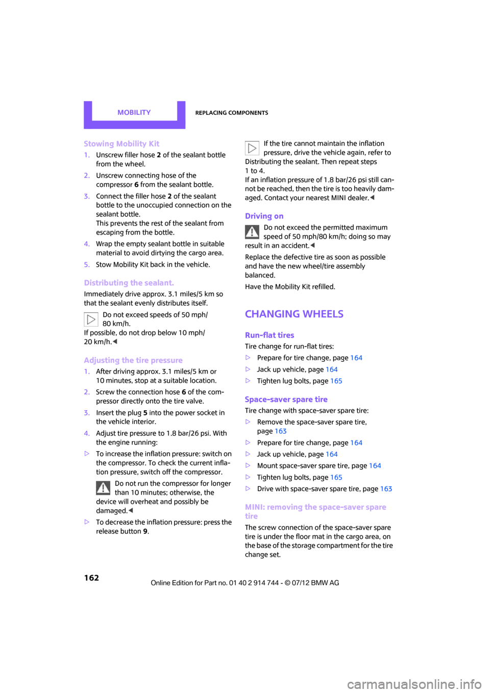
Stowing Mobility Kit
1.Unscrew filler hose 2 of the sealant bottle
from the wheel.
2. Unscrew connecting hose of the
compressor 6 from the sealant bottle.
3. Connect the filler hose 2 of the sealant
bottle to the unoccupied connection on the
sealant bottle.
This prevents the rest of the sealant from
escaping from the bottle.
4. Wrap the empty sealant bottle in suitable
material to avoid dirt ying the cargo area.
5. Stow Mobility Kit back in the vehicle.
Distributing the sealant.
Immediately drive approx. 3.1 miles/5 km so
that the sealant evenly distributes itself.
Do not exceed speeds of 50 mph/
80 km/h.
If possible, do not drop below 10 mph/
20 km/h. <
Adjusting the tire pressure
1.After driving approx. 3.1 miles/5 km or
10 minutes, stop at a suitable location.
2. Screw the connection hose 6 of the com-
pressor directly onto the tire valve.
3. Insert the plug 5 into the power socket in
the vehicle interior.
4. Adjust tire pressure to 1.8 bar/26 psi. With
the engine running:
> To increase the inflatio n pressure: switch on
the compressor. To ch eck the current infla-
tion pressure, switch off the compressor.
Do not run the comp ressor for longer
than 10 minutes; otherwise, the
device will overheat and possibly be
damaged.<
> To decrease the inflation pressure: press the
release button 9. If the tire cannot m
aintain the inflation
pressure, drive the vehicle again, refer to
Distributing the sealan t. Then repeat steps
1to4.
If an inflation pressure of 1.8 bar/26 psi still can-
not be reached, then the tire is too heavily dam-
aged. Contact your ne arest MINI dealer.<
Driving on
Do not exceed the permitted maximum
speed of 50 mph/80 km/h; doing so may
result in an accident. <
Replace the defective tire as soon as possible
and have the new wheel/tire assembly
balanced.
Have the Mobility Kit refilled.
Changing wheels
Run-flat tires
Tire change for run-flat tires:
> Prepare for tire change, page 164
> Jack up vehicle, page 164
> Tighten lug bolts, page 165
Space-saver spare tire
Tire change with space-saver spare tire:
>Remove the space-saver spare tire,
page 163
> Prepare for tire change, page 164
> Jack up vehicle, page 164
> Mount space-saver spare tire, page 164
> Tighten lug bolts, page 165
> Drive with space-saver spare tire, page 163
MINI: removing the space-saver spare
tire
The screw connection of the space-saver spare
tire is under the floor mat in the cargo area, on
the base of the storage compartment for the tire
change set.
Online Edition for Part no. 01 40 2 914 744 - \251 07/12 BMW AG
Page 164 of 207

Replacing componentsMOBILITY
163
1.Unscrew the screw connection with the
special wrench.
2. Take out the cover panel.
3. Screw the lifting handle from the toolkit onto
the thread.
4. Raise the lifting handle slightly.
5. Squeeze the securing spring.
6. The space-saver spare tire is released and
must be held by the lifting handle.
7. Lower the space-saver spare tire with the
lifting handle.
8. Unscrew the lifting handle. 9.
Pull the space-saver spare tire underneath
the vehicle out toward the rear.
10. Position the space-saver spare tire with the
valve facing upward.
11. Unscrew the valve extension from the valve
of the space-saver spare tire.
12. Unscrew the dust cap from the extension
and place it on the va lve of the space-saver
spare tire.
Due to its different dimensions, the
damaged wheel cannot be placed in the
recess for the space-saver spare tire. <
MINI Clubman: removing the space-
saver spare tire
The space-saver spare tire is located under the
tire change set in the cargo area.
1.Fold up the floor mat.
2. Unscrew the nut, arrow, and remove the
space-saver spare tire.
Driving with the space-saver spare tire
Drive cautiously and do not exceed a
speed of 50 mph/80 km/h. Changes may
occur in vehicle handling such as lower track
Online Edition for Part no. 01 40 2 914 744 - \251 07/12 BMW AG