engine MINI Clubman 2013 Owner's Guide
[x] Cancel search | Manufacturer: MINI, Model Year: 2013, Model line: Clubman, Model: MINI Clubman 2013Pages: 267, PDF Size: 3.63 MB
Page 62 of 267

Controls overviewCONTROLS
61
1."Settings"
2. "Language/Units"
3. Select the desired menu item.
4. Select the desired unit.
Service requirements
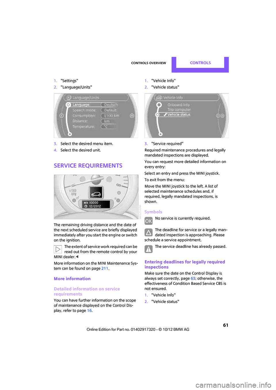
The remaining driving dist ance and the date of
the next scheduled service are briefly displayed
immediately after you start the engine or switch
on the ignition.
The extent of service work required can be
read out from the remo te control by your
MINI dealer. <
More information on th e MINI Maintenance Sys-
tem can be found on page 211.
More information
Detailed information on service
requirements
You can have further information on the scope
of maintenance displayed on the Control Dis-
play, refer to page 16. 1.
"Vehicle Info"
2. "Vehicle status"
3. "Service required"
Required maintenance procedures and legally
mandated inspections are displayed.
You can request more de tailed information on
every entry:
Select an entry and press the MINI joystick.
To exit from the menu:
Move the MINI joystick to the left. A list of
selected maintenance schedules and, if
required, legally mandated inspections, is
shown.
Symbols
No service is currently required.
The deadline for service or a legally man-
dated inspection is approaching. Please
schedule a service appointment.
The service deadline has already passed.
Entering deadlines for legally required
inspections
Make sure the date on the Control Display is
always set correctly, page 63; otherwise, the
effectiveness of Condition Based Service CBS is
not ensured.
1. "Vehicle Info"
2. "Vehicle status"
00320051004F004C00510048000300280047004C0057004C005200510003
Page 69 of 267

CONTROLSTechnology for driving comfort and safety
68
Technology for driving comfort and
safety
Vehicle equipment
In this chapter, all production, country, and
optional equipment that is offered in the model
range is described. Equipment is also described
that is not available because of, for example,
selected options or coun try version. This also
applies to safety relate d functions and systems.
Park Distance Control
PDC
The concept
PDC assists you with parking in reverse. Acoustic
signals and a visual indi cator warn you of the
presence of an object behind the vehicle. To
measure the distance, there are four ultrasonic
sensors in either bumper.
These sensors have a range of approx.
6.5 ft/2 m. However, an acoustic warning
does not sound until an object is approx. 24 in/
60 cm from the rear corner sensors, or approx.
5 ft/1.50 m from the rear center sensors.PDC is a
parking aid that can indicate objects when they
are approached slowly, as is usually the case
when parking. Avoid appr oaching an object at
high speed; otherwise, physical circumstances
may lead to the system warning being issued
too late. <
Automatic mode
With the engine running or the ignition switched
on, the system is activated automatically after
approx. 1 second when you engage reverse
gear or move the automatic transmission selec-
tor lever to position R. Wait this short period
before driving.
Acoustic signals
As the distance between vehicle and object
decreases, the intervals between the tones
become shorter. If the distance to the nearest
object falls to below roughly 1 ft/30 cm, then a
continuous tone sounds.
If the distance remains co nstant, e.g. when driv-
ing parallel to a wall, the acoustic signal stops
after approx. 3 seconds.
Malfunction
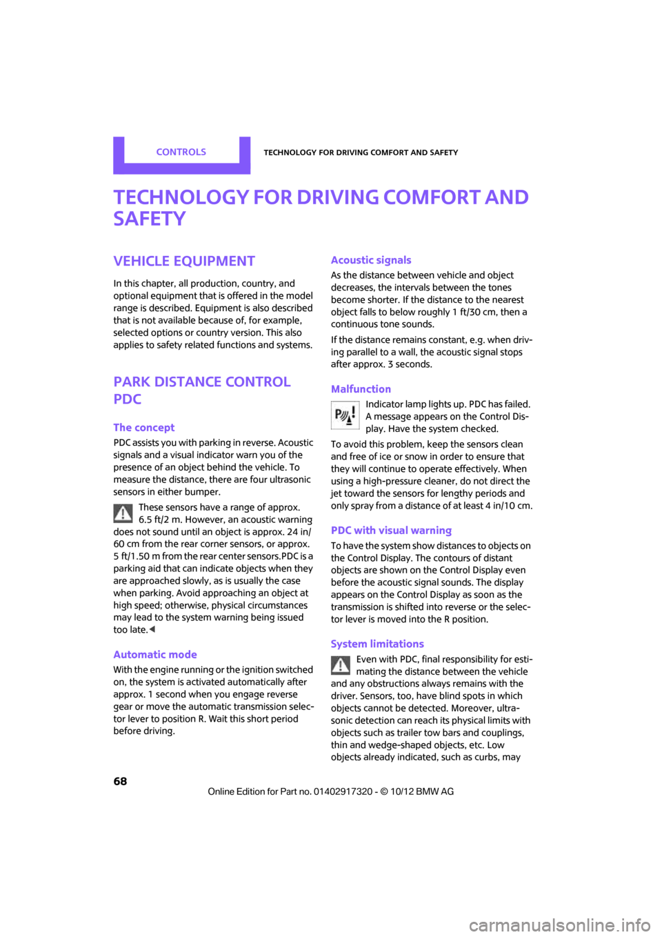
Indicator lamp lights up. PDC has failed.
A message appears on the Control Dis-
play. Have the system checked.
To avoid this problem, keep the sensors clean
and free of ice or snow in order to ensure that
they will continue to operate effectively. When
using a high-pressure cleaner, do not direct the
jet toward the sensors for lengthy periods and
only spray from a distance of at least 4 in/10 cm.
PDC with visual warning
To have the system show distances to objects on
the Control Display. The contours of distant
objects are shown on the Control Display even
before the acoustic sign al sounds. The display
appears on the Control Display as soon as the
transmission is shifted into reverse or the selec-
tor lever is moved into the R position.
System limitations
Even with PDC, final responsibility for esti-
mating the distance between the vehicle
and any obstructions always remains with the
driver. Sensors, too, have blind spots in which
objects cannot be dete cted. Moreover, ultra-
sonic detection can reach its physical limits with
objects such as trailer tow bars and couplings,
thin and wedge-shaped objects, etc. Low
objects already indicated, such as curbs, may
00320051004F004C00510048000300280047004C0057004C005200510003
Page 70 of 267

Technology for driving comfort and safetyCONTROLS
69
enter the sensors' blind spots before or after a
continuous audible signal is given. Higher, pro-
truding objects, such as wall ledges, may not be
detectable. Therefore, always drive cautiously;
otherwise, there is a risk of personal injury or
property damage. Loud sound sources outside
or inside the car can drown out the PDC signal. <
Driving stability control
systems
Your MINI has a number of systems that help to
maintain the vehicle's st ability even in adverse
driving conditions.
The laws of physics cannot be repealed,
even with driving stability control systems.
An appropriate driving style always remains the
responsibility of the driver. Therefore do not
reduce the additional safety margin by engaging
in hazardous driving thereby running the risk of
an accident. <
Antilock Brake System ABS
ABS prevents locking of the wheels during brak-
ing. Safe steering respon se is maintained even
during full braking. Act ive safety is thus
increased.
Braking safely, refer to page 101.
ABS is operational every time you start the
engine.
Cornering Brake Control CBC
Driving stability and steering characteristics are
further enhanced while braking in turns or dur-
ing a lane change.
Electronic brake-forc e distribution EBV
The system controls the brake pressure in the
rear wheels to ensure stable braking behavior.
Brake Assist
Rapidly depressing the brake causes this system
to automatically develop maximum braking force. Thus, the system helps keep braking dis-
tance to a minimum. At the same time, all the
benefits provided by ABS are exploited.
Do not reduce the pressure on the brake for the
duration of the full braking application.
Dynamic Stability Control DSC
The concept
DSC prevents the driving wheels from losing
traction when you pull away from rest or accel-
erate.
DSC also detects unstable driving conditions
such as when the vehicle'
s rear end fishtails or
the vehicle is sliding on its front wheels. In these
cases, DSC helps the vehicle maintain a safe
course within physical limits by reducing engine
output and through brakin g actions at the indi-
vidual wheels.
Every time that the engine is started, DSC is
ready to operate.
Deactivating DSC
Press the button until the DSC OFF indicator
lamp on the speedometer is on and DSC OFF is
displayed on the tachometer. DSC is deacti-
vated. Stabilizing and propulsion promoting
actions are no longer executed.
When driving with snow chains or to 'rock free'
in snow, it can be helpfu l to switch off DSC for a
brief period.
To increase vehicle stability, activate DSC again
as soon as possible.
00320051004F004C00510048000300280047004C0057004C005200510003
Page 72 of 267

Technology for driving comfort and safetyCONTROLS
71
Deactivating both DTC and DSC
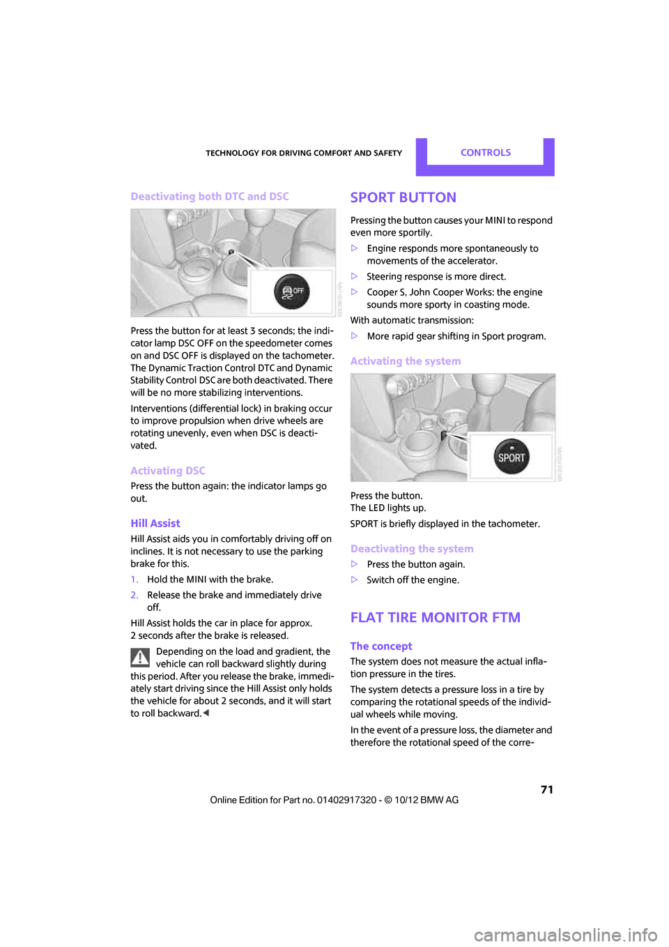
Press the button for at least 3 seconds; the indi-
cator lamp DSC OFF on the speedometer comes
on and DSC OFF is displayed on the tachometer.
The Dynamic Traction Control DTC and Dynamic
Stability Control DSC are both deactivated. There
will be no more stab ilizing interventions.
Interventions (differentia l lock) in braking occur
to improve propulsion when drive wheels are
rotating unevenly, even when DSC is deacti-
vated.
Activating DSC
Press the button again: the indicator lamps go
out.
Hill Assist
Hill Assist aids you in co mfortably driving off on
inclines. It is not necessary to use the parking
brake for this.
1. Hold the MINI with the brake.
2. Release the brake and immediately drive
off.
Hill Assist holds the car in place for approx.
2 seconds after the brake is released. Depending on the load and gradient, the
vehicle can roll backwa rd slightly during
this period. After you release the brake, immedi-
ately start driving since the Hill Assist only holds
the vehicle for about 2 seconds, and it will start
to roll backward. <
Sport button
Pressing the button causes your MINI to respond
even more sportily.
>Engine responds more spontaneously to
movements of the accelerator.
> Steering response is more direct.
> Cooper S, John Cooper Works: the engine
sounds more sporty in coasting mode.
With automatic transmission:
> More rapid gear shifting in Sport program.
Activating the system
Press the button.
The LED lights up.
SPORT is briefly displayed in the tachometer.
Deactivating the system
>Press the button again.
> Switch off the engine.
Flat Tire Monitor FTM
The concept
The system does not me asure the actual infla-
tion pressure in the tires.
The system detects a pre ssure loss in a tire by
comparing the rotational speeds of the individ-
ual wheels while moving.
In the event of a pressure loss, the diameter and
therefore the rotational speed of the corre-
00320051004F004C00510048000300280047004C0057004C005200510003
Page 73 of 267

CONTROLSTechnology for driving comfort and safety
72
sponding wheel change. This is detected and
reported as a flat tire.
Functional requirement
The system must have been initialized while the
tire inflation pressure was correct; otherwise,
reliable signaling of a fl at tire is not ensured.
Initialize the system afte r every correction of the
tire inflation pressure and after every tire or
wheel change.
System limitations
Sudden serious tire damage caused by
external influences cannot be indicated in
advance. <
A natural, even pressure loss in all four tires can-
not be detected. Therefore, check the tire infla-
tion pressure regularly.
In the following situations, the system could be
delayed or malfunction:
> System has not been initialized.
> Driving on snowy or sl ippery road surface.
> Performance-oriented style of driving: slip in
the drive wheels, high lateral acceleration.
> Snow chains are attached.
When the vehicle is driven with a space-saver
spare tire, page 228, the Flat Tire Monitor can-
not function.
Status display
The current status of the Flat Tire Monitor can be
displayed on the Control Display, e.g. whether or
not the FTM is active.
1. "Vehicle Info"
2. "Vehicle status" 3.
"Flat Tire Monitor"
The status is displayed.
Initializing the system
The initialization process adopts the set inflation
tire pressures as refere nce values for the detec-
tion of a flat tire. Initia lization is started by con-
firming the inflation pressures.
Do not initialize the syst em when driving with
snow chains.
1. "Vehicle Info"
2. "Vehicle status"
3. "Reset"
4. Start the engine, but do not start driving.
5. Select "Reset" to start the initialization.
6. Start to drive.
The initialization is completed during driv-
ing, which can be interrupted at any time.
When driving resumes, the initialization is con-
tinued automatically. <
00320051004F004C00510048000300280047004C0057004C005200510003
Page 76 of 267

Technology for driving comfort and safetyCONTROLS
75
>Interference from systems or devices with
the same transmission frequency.
> Malfunction.
Resetting the system
Reset the system again after each correction of
the tire inflation pressure and after every tire or
wheel change.
1. "Vehicle Info"
2. "Vehicle status"
3. "Reset"
4. Start the engine – do not drive away.
5. Select "Reset" to start the initialization.
6. Start to drive.
The tires are shown in gray and "Resetting
TPM..." is displayed.
After driving a few minutes, the set inflation
pressures in the tires are accepted as the target
values to be monitored. The resetting process is
completed automatically as you drive. The tires
are depicted in green on the Control Display and
"Status: TPM active" is displayed again.
The trip can be interrupted at any time. When
driving resumes, resetting is continued auto-
matically. If a flat tire is detected while the system is
resetting, all tires on the Control Display
are displayed in yellow. The message "Low tire!"
is displayed. <
Message for low tire inflation pressure
The warning lamps come on in yellow
and red. A message appears on the
onboard computer. An acoustic signal
also sounds.
> There is a flat tire or substantial loss of tire
pressure in the indicated wheel.
> The system was not reset after a wheel
change and thus issues a warning based on
the inflation pressures initialized last.
1. Reduce speed and stop the vehicle with cau-
tion. Avoid sudden braking and steering
maneuvers.
2. Check whether the vehicle is equipped with
normal tires or with run-flat tires.
Run-flat tires, refer to page 205, are identi-
fied by a circular symbol containing the let-
ters RSC on the tire sidewall.
When a low inflation pressure is reported, the
Dynamic Stability Control DSC is activated.
Actions in the event of a flat tire
Normal tires
1. Identify the damaged tire.
To do so, check the inflation pressure in all
four tires. The inflation pressure display of
the Mobility Kit, refer to page 224, can be
used for this.
If the inflation pressure is correct in all four
tires, then the Tire Pressure Monitor may not
have been reset. The system must then be
reset.
If it is not possible to identify the damaged
tire, contact your MINI dealer.
2. Use the Mobility Kit to remedy the flat tire on
the damaged wheel, refer to page 224, or to
replace the damaged wheel, refer to
page. 227.
The use of tire sealant, e.g. Mobility Kit, can
damage the TPM wheel electronics. In this
case, have the electronics checked and
00320051004F004C00510048000300280047004C0057004C005200510003
Page 82 of 267

LampsCONTROLS
81
Lamps
Vehicle equipment
In this chapter, all production, country, and
optional equipment that is offered in the model
range is described. Equipment is also described
that is not available because of, for example,
selected options or count ry version. This also
applies to safety related functions and systems.
Parking lamps/low beams
0 Lamps off / daytime running lights
1 Parking lamps and daytime running lights
2 Low-beam headlamps and welcome lamps
3 Automatic headlamp control, daytime run-
ning lights, welcome lamps, and Adaptive
Light Control
When you open the driver's door with the igni-
tion switched off, the exterior lighting is auto-
matically switched off if the light switch is in
position 0, 2 or 3.
Switch on the parking lamps if necessary, switch
position 1.
Parking lamps
Turn the light switch to position 1.
The front, rear and side vehicle lighting is
switched on.
Activation of lights on one side of the vehicle for
parking, page 83. The parking lamps will discharge the bat-
tery. Therefore, do not leave them on for
unduly long periods of time; otherwise, the bat-
tery might not have enough power to start the
engine. <
Low beams
Turn the light switch to position 2.
The low beams come on when the ignition is on.
Automatic headlamp control
When the switch is in position 3, the low beams
are switched on and of f automatically depend-
ing on ambient light condit ions, e.g. in a tunnel,
in twilight, or if there is precipitation. Adaptive
Light Control is active.
The headlamps may also come on when the sun
is sitting low on a blue sky.
When driving into tunnels with bright overhead
lights, there may be a delay before the head-
lamps come on.
The low beams remain switched on indepen-
dent of the ambient lighting conditions when
you switch on the fog lamps.
If the daytime running lights are activated,
page 82, the low beams are al ways switched on
with the light switch in position 3 and the igni-
tion on. The exterior lamps are automatically
switched off after the vehicle is parked.
The automatic headlamp control cannot
serve as a substitute for your personal
judgment in determin ing when the lamps
should be switched on in response to ambient
lighting conditions. For example, the system
cannot detect fog or hazy weather. To avoid
safety risks, you should respond to these kinds
of low-visibility situations by switching the head-
lamps on manually. <
00320051004F004C00510048000300280047004C0057004C005200510003
Page 84 of 267

LampsCONTROLS
83
In reverse, the Adaptive Light Control is not acti-
vated.
Malfunction
A message is displayed.
The Adaptive Light Control is malfunctioning or
failed. Have the system checked as soon as pos-
sible.
High beams/roadside
parking lamps
1 Turn signals/roadside parking lamps
2 Switching on high beams
3 Switching off high be ams/headlamp flasher
Roadside parking lamps, left or right
The vehicle can be illumi nated on one side for
parking. Comply with local regulations when
doing so.
Switching on
After parking the vehicle, press the lever up or
down, arrow 1 .
The roadside parking lamps drain the bat-
tery. Therefore, do not leave them on for
unduly long periods of time; otherwise, the bat-
tery might not have enough power to start the
engine. <
Switching off
Press the lever up or down to the pressure point.
Front fog lamps
1Front fog lamps
2 Rear fog lamp
Press the respective switch to turn the lamps on/
off.
Front fog lamps
The parking lamps or low beams must be
switched on for the fog lamps to operate. The
green indicator lamp lights up when the fog
lamps are switched on.
Depending on your vehicle's equipment, the fog
lamps are switched off when you activate the
headlamp flasher or switch on the high beams.
If the automatic headlamp control is acti-
vated, the low beams will come on auto-
matically when you switch on the fog lamps. <
Rear fog lamp
The low beams or parking lamps with fog lamps
must be switched on. The yellow indicator lamp
comes on when the rear fog lamp is switched on.
Instrument lighting
You can adjust the brightness of the instrument
lighting only when the parking lamps or the low
beams are on.
The intensity of the brightness changes up to a
predetermined end point, and then decreases.
00320051004F004C00510048000300280047004C0057004C005200510003
Page 87 of 267

CONTROLSClimate
86
Air vents
3Airflow directed toward the windshield and
side windows 4
Air to the upper body area, draft-free venti-
lation
5 Air to the footwell
Air conditioner
1Air flow rate
2 Cooling function
3 Recirculated-air mode
4 Temperature 5
Rear window defroster
6 Air distribution
7 Windshield heating
Air flow rate
Adjust the air flow rate. The higher the
rate, the more effective the heating or
cooling will be.
The air flow rate is lowered or switched off
entirely to reduce the drain on the battery.
Switching the system on/off
Turn the air flow rate rota ry switch to 0. Blower
and air conditioner are co mpletely switched off
and the air supply is cut off.
Set any desired air flow rate to switch on the air
conditioner.
Cooling function
When the cooling function is on,
the air is cooled, dried, then
reheated according to the temper-
ature setting. The passenger compartment can
only be cooled while the engine is running.
The cooling function helps prevent condensa-
tion on the windows or removes it quickly. Depending on the weather, the windshield may
fog over briefly when the engine is started.
To cool the air more quickly and intensely
when the external temperature is high,
you can switch on the recirculated-air mode.<
Recirculated-air mode
If the air outside the car has an
unpleasant odor or contains pollut-
ants, shut off the supply to the inte-
rior of the car temporarily. The system then
recirculates the air currently within the vehicle.
If condensation starts to form on the inside win-
dow surfaces, press the AUTO button or switch
off the recirculated-air mode and, if necessary,
increase the air flow ra te. Ensure that air can
flow onto the windshield.
The recirculated-air mode is automatically deac-
tivated at low outside temperatures.
The recirculated-air mode should not be
used over an extended period of time;
00320051004F004C00510048000300280047004C0057004C005200510003
Page 90 of 267

ClimateCONTROLS
89
Temperature
Set the desired temperature individually.
The automatic climate control achieves
this temperature as quickly as possible
regardless of the season, using maximum
cooling or heating power if necessary, and then
maintains it.
If you switch between different tempera-
ture settings in quic k succession, the auto-
matic climate control do es not have enough
time to achieve the set temperature. <
Rear window defroster
The defroster is switched off auto-
matically after a certain time.
Defrosting windows and removing
condensation
Quickly removes ice and condensa-
tion from the windshield and front
side windows.
For this purpose, also switch on the
cooling function.
The windshield heating is switched on automat-
ically.
Windshield heating
The windshield heating is switched
off automatically after a certain
time.
Cooling function
When the cooling function is on,
the air is cooled, dried, then
reheated according to the temper-
ature setting. The passenger com-
partment can only be cooled while
the engine is running.
The cooling function helps prevent condensa-
tion on the windows or removes it quickly. Depending on the weather, the windshield may
fog over briefly when the engine is started. The
recirculated-air mode may be switched on auto-
matically.
When the AUTO button is pressed, the cooling
function switches on automatically.
Microfilter/activated-charcoal filter
The microfilter captures dust and pollen. The
activated-charcoal filter provides additional pro-
tection by filtering gase
ous pollutants from the
outside air. Your MINI dealer replaces this com-
bined filter as a standard part of your scheduled
maintenance.
You can call up further information in the service
requirements display, page 61.
Ventilation
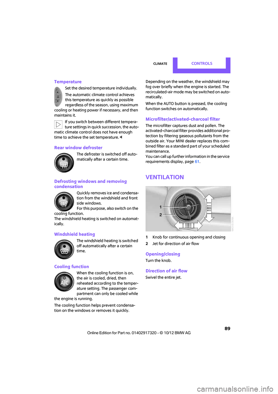
1 Knob for continuous opening and closing
2 Jet for direction of air flow
Opening/closing
Turn the knob.
Direction of air flow
Swivel the entire jet.
00320051004F004C00510048000300280047004C0057004C005200510003