lock MINI Clubman 2014 (Mini Connected) Owner's Guide
[x] Cancel search | Manufacturer: MINI, Model Year: 2014, Model line: Clubman, Model: MINI Clubman 2014Pages: 276, PDF Size: 6.44 MB
Page 63 of 276
Manually unlocking the selector lever
lock
If the selector lever is locked in position P al‐
though the ignition is switched on, the brake is
depressed, and the button on the selector lever
is pressed, the selector lever lock can be over‐
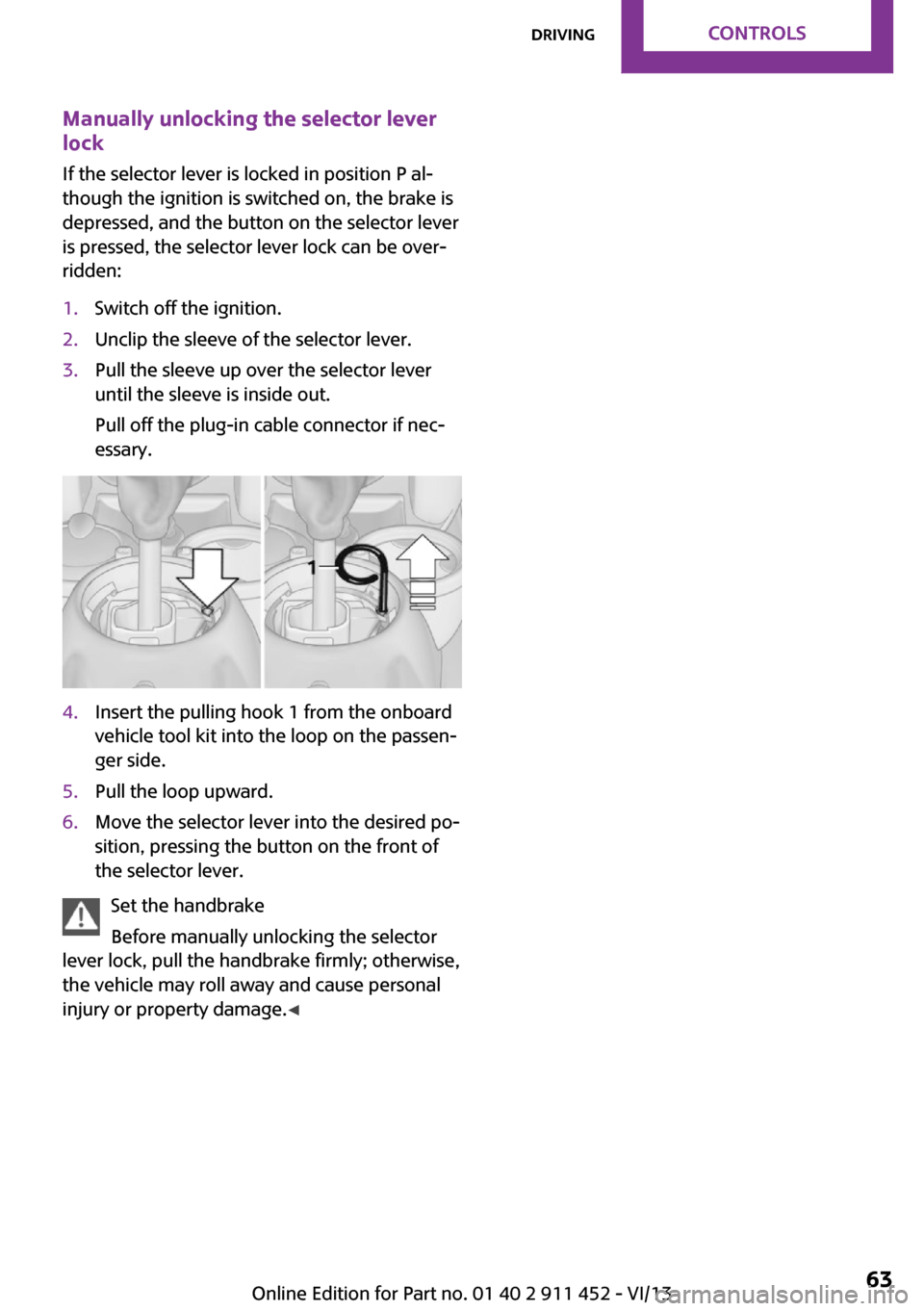
ridden:1.Switch off the ignition.2.Unclip the sleeve of the selector lever.3.Pull the sleeve up over the selector lever
until the sleeve is inside out.
Pull off the plug-in cable connector if nec‐
essary.4.Insert the pulling hook 1 from the onboard
vehicle tool kit into the loop on the passen‐
ger side.5.Pull the loop upward.6.Move the selector lever into the desired po‐
sition, pressing the button on the front of
the selector lever.
Set the handbrake
Before manually unlocking the selector
lever lock, pull the handbrake firmly; otherwise,
the vehicle may roll away and cause personal
injury or property damage. ◀
Seite 63DrivingControls63
Online Edition for Part no. 01 40 2 911 452 - VI/13
Page 64 of 276
DisplaysVehicle equipment
This chapter describes all series equipment as
well as country-specific and special equipment
offered for this model series.Therefore, it also
describes equipment that may not be found in
your vehicle, for instance due to the selected
special equipment or the country version. This
also applies to safety-related functions and sys‐
tems.
Odometer, external tem‐
perature display, clock
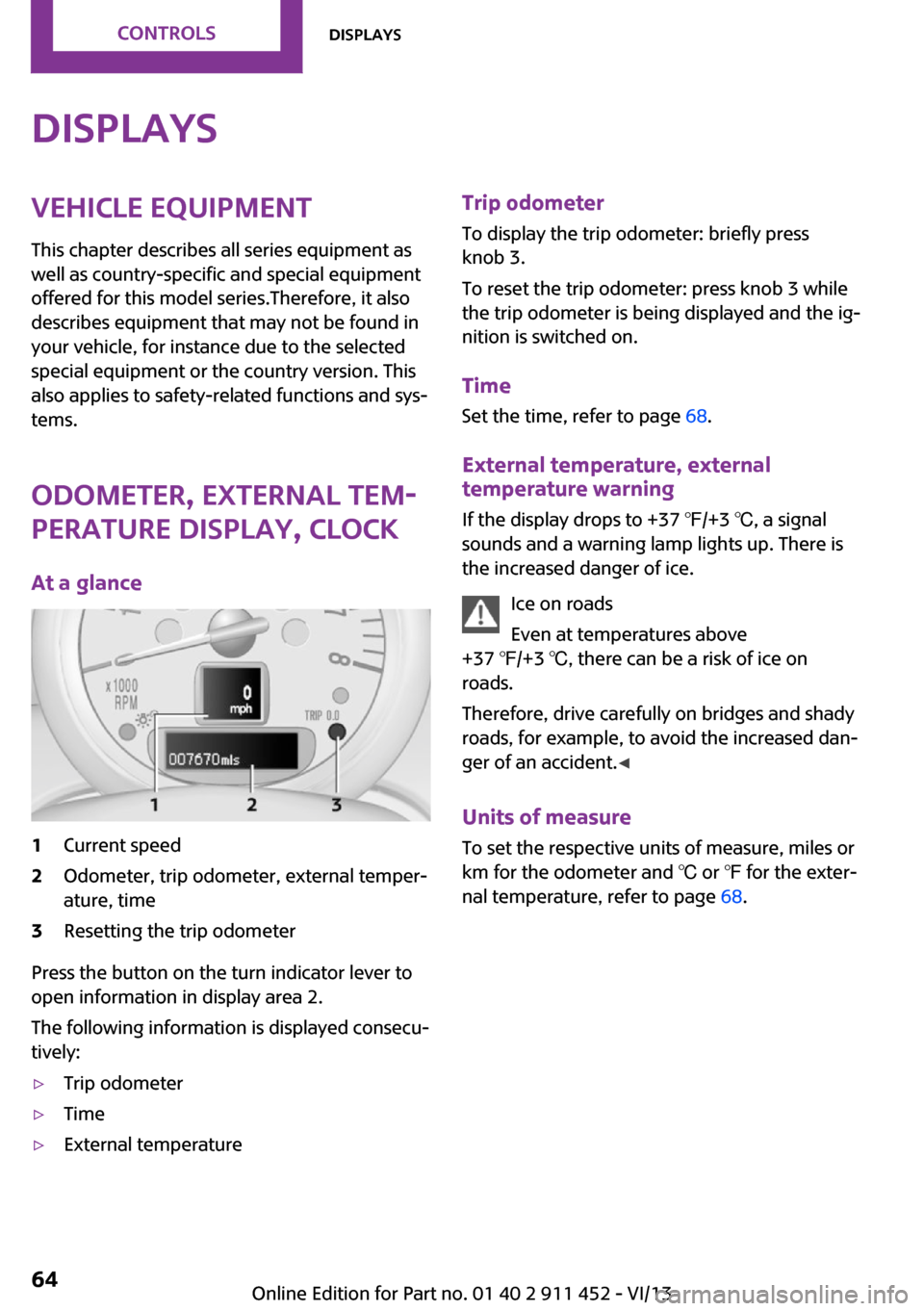
At a glance1Current speed2Odometer, trip odometer, external temper‐
ature, time3Resetting the trip odometer
Press the button on the turn indicator lever to
open information in display area 2.
The following information is displayed consecu‐
tively:
▷Trip odometer▷Time▷External temperatureTrip odometer
To display the trip odometer: briefly press
knob 3.
To reset the trip odometer: press knob 3 while
the trip odometer is being displayed and the ig‐
nition is switched on.
Time Set the time, refer to page 68.
External temperature, external temperature warning
If the display drops to +37 ℉/+3 ℃, a signal
sounds and a warning lamp lights up. There is
the increased danger of ice.
Ice on roads
Even at temperatures above
+37 ℉/+3 ℃, there can be a risk of ice on
roads.
Therefore, drive carefully on bridges and shady
roads, for example, to avoid the increased dan‐
ger of an accident. ◀
Units of measure
To set the respective units of measure, miles or
km for the odometer and ℃ or ℉ for the exter‐
nal temperature, refer to page 68.Seite 64ControlsDisplays64
Online Edition for Part no. 01 40 2 911 452 - VI/13
Page 68 of 276
Next setting or information1.Within a setting or information display,
press the button on the turn indicator lever
repeatedly until "NEXT" is displayed.2.Hold the button down.
Direct change to the next setting or piece of in‐
formation.
Units of measure
The units of measure, such as for fuel consump‐
tion, route/distance, and temperature, can be
changed. The settings are stored for the remote
control currently in use.
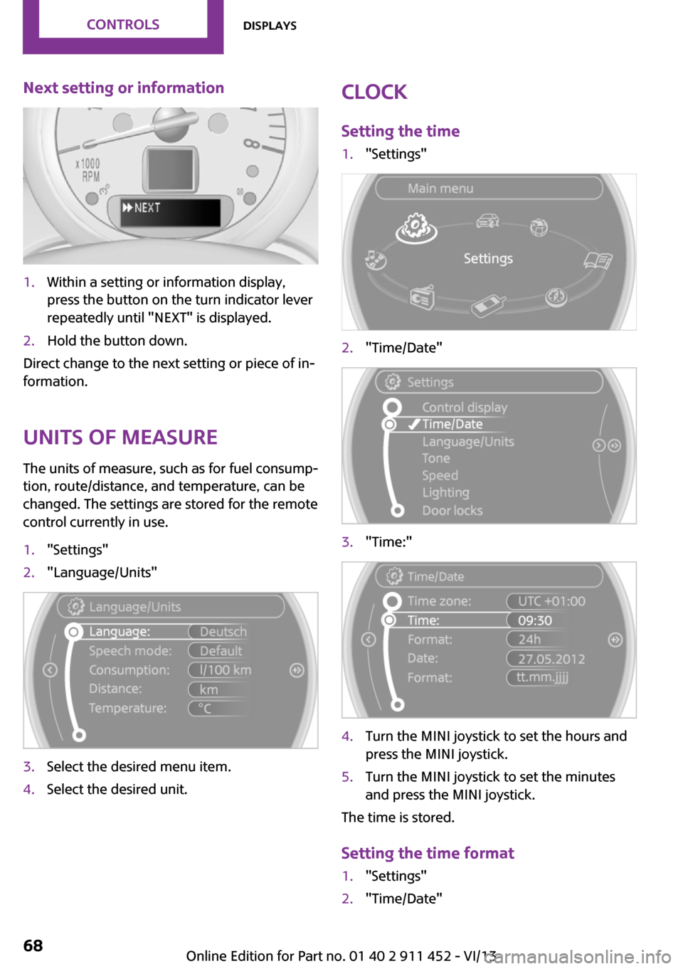
1."Settings"2."Language/Units"3.Select the desired menu item.4.Select the desired unit.Clock
Setting the time1."Settings"2."Time/Date"3."Time:"4.Turn the MINI joystick to set the hours and
press the MINI joystick.5.Turn the MINI joystick to set the minutes
and press the MINI joystick.
The time is stored.
Setting the time format
1."Settings"2."Time/Date"Seite 68ControlsDisplays68
Online Edition for Part no. 01 40 2 911 452 - VI/13
Page 75 of 276

When the daytime running lights are activated,
the low beams are always switched on in
switch position 3 when the ignition is switched
on.
The exterior lighting goes out automatically af‐
ter the vehicle is switched off.
High beams/roadside parking lamps1Turn signal/roadside parking lamp2Switching on the high beams3Switching off the high beams/headlamp
flasher
To assist in parking, the vehicle can be illumi‐
nated on one side; note the country-specific
regulations.
The roadside parking lamps drain the battery.
Therefore, do not leave them on for unduly
long periods of time; otherwise, the battery
might not have enough power to start the en‐
gine.
Switching on the roadside parking lamp
To switch on the roadside parking lamp on the
left or right, press the turn indicator lever up or
down after switching off the vehicle, arrow 1.
Switching off the roadside parking lamp
Press the lever up or down to the resistance
point.
Daytime running lights
The daytime running lights light up in switch
position 0, 1, or 3 when the ignition is switched
on.
The exterior lighting goes out automatically af‐
ter the vehicle is switched off.
In switch position 1, the parking lamps light up
after the ignition is switched off.
Activating/deactivating1."Settings"2."Lighting"3."Daytime running lamps"
The setting is stored for the remote control cur‐
rently in use.
Welcome lamps If the light switch stays in switch position 2 or 3
after the vehicle is switched off, the parking
lamps and the interior lamps light up for a cer‐
tain period when the vehicle is unlocked.
Headlamp courtesy delay feature The low beams stay lit for a short while after
the ignition is switched off, if the lamps are
switched off and the headlamp flasher is
switched on.
Setting the duration
1."Settings"2."Lighting"Seite 75LampsControls75
Online Edition for Part no. 01 40 2 911 452 - VI/13
Page 78 of 276

SafetyVehicle equipment
This chapter describes all series equipment as
well as country-specific and special equipment
offered for this model series.Therefore, it also
describes equipment that may not be found in
your vehicle, for instance due to the selected
special equipment or the country version. This
also applies to safety-related functions and sys‐
tems.
Airbags1Front airbags2Side airbags3Head airbags
Front airbags
Front airbags help protect the driver and front
passenger by responding to frontal impacts in
which safety belts alone cannot provide ade‐
quate restraint.
Side airbags
In a lateral impact, the side airbag supports the
side of the body in the chest and lap area.
Head airbags
In a lateral impact, the head airbag supports
the head.
Protective action
Airbags are not triggered in every impact situa‐
tion, e.g., in less severe accidents or rear-end
collisions.
Information on how to ensure the opti‐
mal protective effect of the airbags▷Keep at a distance from the airbags.▷Always grasp the steering wheel on the
steering wheel rim, holding your hands at
the 3 o'clock and 9 o'clock positions, to
keep the danger of injury to your hands or
arms as low as possible if the airbag is trig‐
gered.▷There should be no people, animals, or ob‐
jects between an airbag and a person.▷Do not use the cover of the front airbag on
the front passenger side as a storage area.▷Keep the dashboard and window on the
front passenger side clear, i.e., do not cover
with adhesive labels or coverings, and do
not attach holders such as for navigation in‐
struments and mobile phones.▷Make sure that the front passenger is sitting
correctly, i.e., keeps his or her feet and legs
in the footwell; otherwise, leg injuries can
occur if the front airbag is triggered.▷Do not place slip covers, seat cushions or
other objects on the front passenger seat
that are not approved specifically for seats
with integrated side airbags.▷Do not hang pieces of clothing, such as
jackets, over the backrests.▷Make sure that occupants keep their heads
away from the side airbag and do not rest
against the head airbag; otherwise, injuries
can occur if the airbags are triggered.▷Do not remove the airbag restraint system.▷Do not remove the steering wheel.Seite 78ControlsSafety78
Online Edition for Part no. 01 40 2 911 452 - VI/13
Page 88 of 276
Driving stability control systemsVehicle equipment
This chapter describes all series equipment as
well as country-specific and special equipment
offered for this model series.Therefore, it also
describes equipment that may not be found in
your vehicle, for instance due to the selected
special equipment or the country version. This
also applies to safety-related functions and sys‐
tems.
Antilock Brake System
ABS
ABS prevents locking of the wheels duringbraking.
Steerability is maintained even during full brak‐
ing. This increases active driving safety.
ABS is operational every time you start the en‐
gine.
Electronic brake-force distribution EBVThe system controls the brake pressure in the
rear wheels to ensure stable braking behavior.
CBC Cornering Brake Control
When braking in curves or during a lane
change, driving stability and steering response
are improved further.
Brake assistant When the brakes are applied rapidly, this sys‐
tem automatically produces the maximum
braking force boost. In this way, the system
helps keep the braking distance as short as
possible. This system utilizes all of the benefits
provided by ABS.Do not reduce the pressure on the brake pedal
for the duration of full braking.
Dynamic Stability Con‐
trol DSC
The concept
DSC prevents traction loss in the driving wheels
when driving away and accelerating.
DSC also recognizes unstable vehicle condi‐
tions, such as fishtailing or nose-diving. Subject
to physical limits, DSC helps to keep the vehicle
on a steady course by reducing engine speed
and by applying brakes to the individual
wheels.
DSC is operational every time you start the en‐
gine.
Adjust your driving style to the situation
An appropriate driving style is always the
responsibility of the driver.
The laws of physics cannot be repealed, even
with DSC.
Do not reduce the additional safety margin
with a risky driving style, as otherwise there is a
risk of an accident. ◀
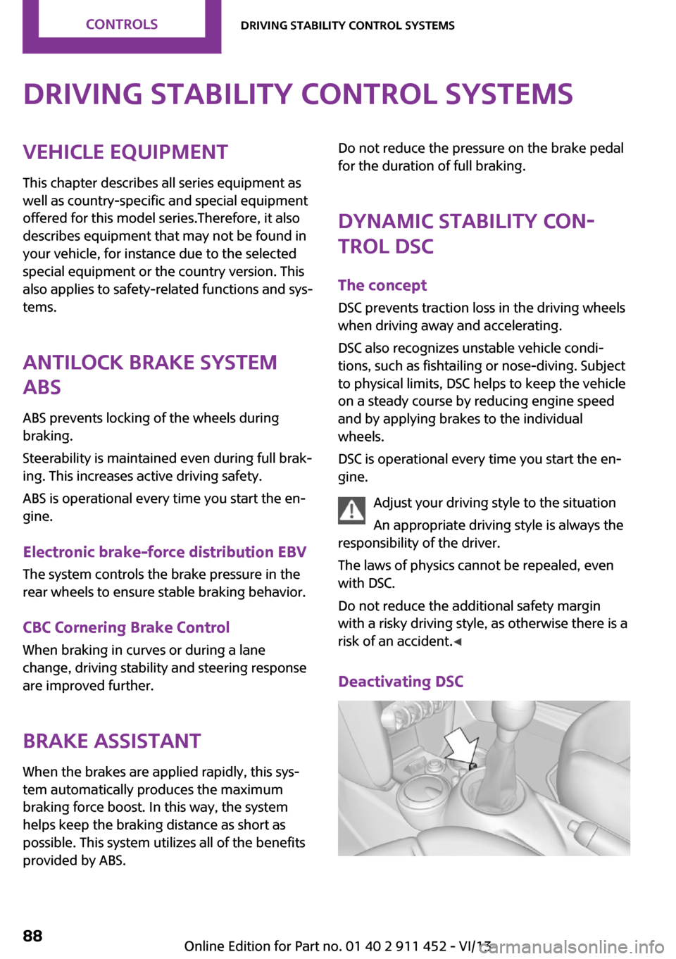
Deactivating DSCSeite 88ControlsDriving stability control systems88
Online Edition for Part no. 01 40 2 911 452 - VI/13
Page 105 of 276
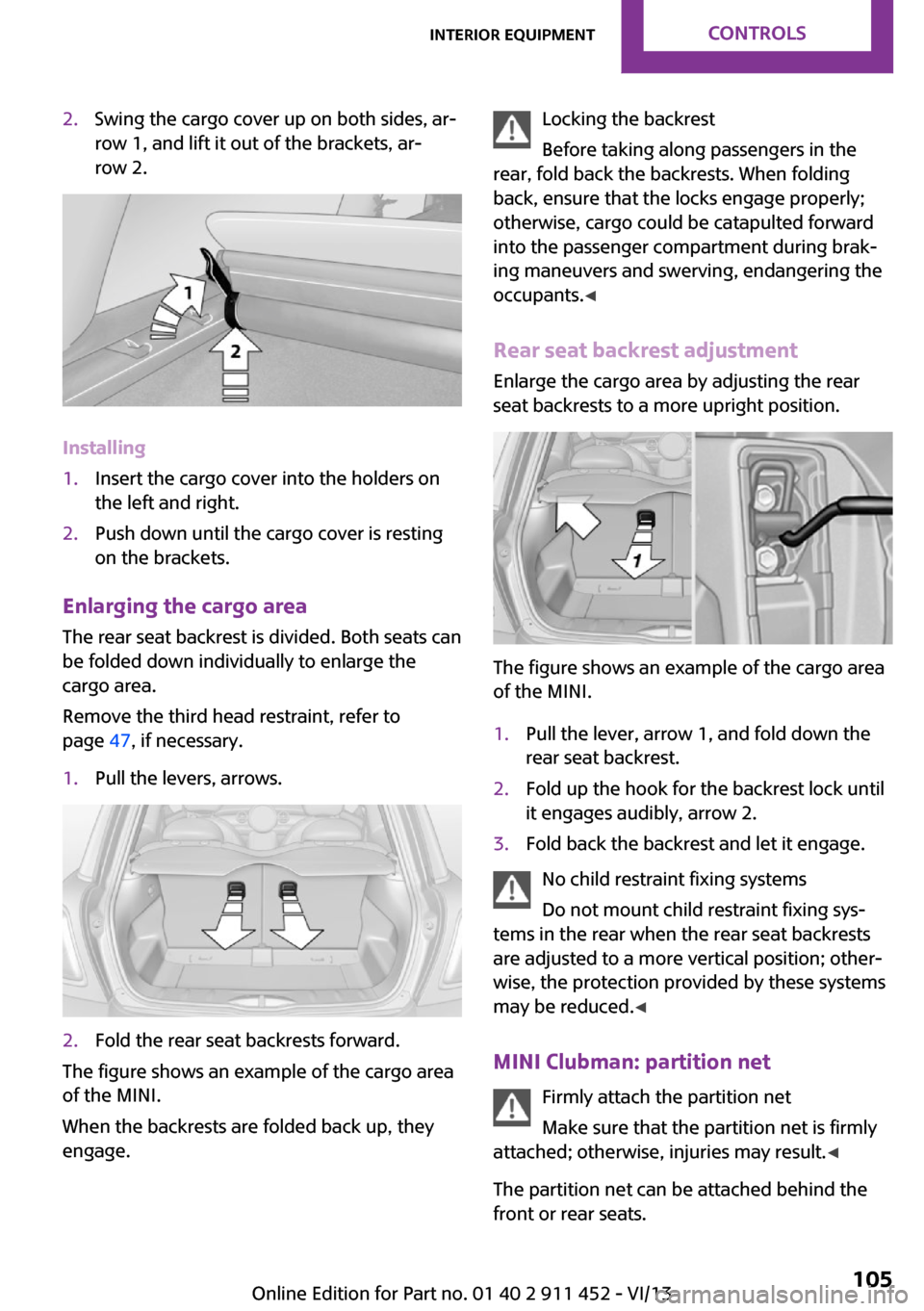
2.Swing the cargo cover up on both sides, ar‐
row 1, and lift it out of the brackets, ar‐
row 2.
Installing
1.Insert the cargo cover into the holders on
the left and right.2.Push down until the cargo cover is resting
on the brackets.
Enlarging the cargo area
The rear seat backrest is divided. Both seats can
be folded down individually to enlarge the
cargo area.
Remove the third head restraint, refer to
page 47, if necessary.
1.Pull the levers, arrows.2.Fold the rear seat backrests forward.
The figure shows an example of the cargo area
of the MINI.
When the backrests are folded back up, they
engage.
Locking the backrest
Before taking along passengers in the
rear, fold back the backrests. When folding
back, ensure that the locks engage properly;
otherwise, cargo could be catapulted forward
into the passenger compartment during brak‐
ing maneuvers and swerving, endangering the
occupants. ◀
Rear seat backrest adjustment
Enlarge the cargo area by adjusting the rear
seat backrests to a more upright position.
The figure shows an example of the cargo area
of the MINI.
1.Pull the lever, arrow 1, and fold down the
rear seat backrest.2.Fold up the hook for the backrest lock until
it engages audibly, arrow 2.3.Fold back the backrest and let it engage.
No child restraint fixing systems
Do not mount child restraint fixing sys‐
tems in the rear when the rear seat backrests
are adjusted to a more vertical position; other‐
wise, the protection provided by these systems
may be reduced. ◀
MINI Clubman: partition net Firmly attach the partition net
Make sure that the partition net is firmly
attached; otherwise, injuries may result. ◀
The partition net can be attached behind the
front or rear seats.
Seite 105Interior equipmentControls105
Online Edition for Part no. 01 40 2 911 452 - VI/13
Page 137 of 276

3."New route for"4.Turn the MINI joystick. Enter the number of
kilometers within which you would like to
return to the original route.5.Press the MINI joystick.
Resuming the original route
If the route section should no longer be by‐
passed:
1."Navigation"2."Route information"3."New route for:"4."Remove blocking"
Gas station recommenda‐
tion
The remaining range is calculated and gas sta‐
tions along the route are displayed if needed.
Even with the latest navigation data, informa‐
tion on individual special destinations may
have changed; for example, gas stations might
not be in operation.
1."Navigation"2."Route information"3."Recommended refuel"
A list of the gas stations is displayed.4.Highlight a gas station.5.Select the gas station.6. Select the symbol.7."Start guidance": destination guidance to
the selected gas station is started.
"Add as another destination": the gas sta‐
tion is added to the route.
Destination guidance
through voice instruc‐
tions
Switching spoken instructions on/off The spoken instructions can be switched on or
off during destination guidance.
The setting is stored for the remote control cur‐
rently in use.
1."Navigation"2."Map"3. Select the symbol.SymbolFunction The spoken instructions are switched
on. Spoken instructions are switched off.
Repeating a spoken instruction
1."Navigation"2."Map"3. Highlight the symbol.4.Press the MINI joystick twice.
Volume of spoken instructions
Turn the volume knob while giving an instruc‐
tion until the desired volume is set.
Seite 137Destination guidanceNavigation137
Online Edition for Part no. 01 40 2 911 452 - VI/13
Page 206 of 276

RefuelingVehicle equipmentThis chapter describes all series equipment as
well as country-specific and special equipment
offered for this model series.Therefore, it also
describes equipment that may not be found in
your vehicle, for instance due to the selected
special equipment or the country version. This
also applies to safety-related functions and sys‐
tems.
General information Refuel promptly
At the latest, refuel at a range below
30 miles/50 km; otherwise, the engine function
is not ensured and damage may occur. ◀
Notes Switch off the engine before refueling
Always switch off the engine before refu‐
eling; otherwise, fuel cannot be added to the
tank and a message will be displayed. ◀
Observe when handling fuel▷Take all precautionary measures and
observe all applicable regulations
when handling fuel.▷Do not carry any spare fuel containers in
your vehicle. They can develop a leak and
cause an explosion or cause a fire in the
event of an accident. ◀
Fuel cap
Opening
1.Open fuel filler flap.2.Turn the fuel cap counterclockwise.3.Place the fuel cap in the bracket attached
to the fuel filler flap.
Closing
1.Fit the fuel cap and turn it clockwise until
you clearly hear a click.2.Close the fuel filler flap.
Do not pinch the retaining strap
Do not pinch the retaining strap attached
to the cap; otherwise, the cap cannot be closed
properly and fuel vapors can escape. ◀
A message is displayed if the cap is loose or
missing.
Manually unlocking fuel filler flap In the event of a malfunction, the fuel filler flap
can be released manually:
Seite 206MobilityRefueling206
Online Edition for Part no. 01 40 2 911 452 - VI/13
Page 219 of 276

Run-flat tiresLabel
The symbol identifying run-flat tires is a circle
with the letters RSC on the sidewall.
Run-flat tires are tires with special rims that
support themselves for a limited period of time.
The sidewall reinforcement ensures that the
tire can continue to be used to a limited extent
if it has lost pressure and even if it has become
completely depressurized.
For continued driving in the event of a flat tire,
refer to page 82.
Correcting a flat tire Safety measures in case of a breakdown
▷Park the vehicle as far as possible
from passing traffic and on solid
ground. Switch on the hazard warn‐
ing system.▷Let the steering wheel lock engage with the
wheels in the straight-ahead position, set
the handbrake, and engage first gear or re‐
verse, or engage selector lever position P.▷Have all vehicle occupants get out of the
vehicle and ensure that they remain out‐
side the immediate area in a safe place,
such as behind a guardrail.▷If a warning triangle or portable hazard
warning lamp is required, set it up on the
roadside at an appropriate distance from
the rear of the vehicle. Comply with all
safety guidelines and regulations. ◀
The procedure to correct a flat tire depends on
the equipment in the vehicle:
▷Run-flat tires, refer to page 219.▷MINI Mobility System, refer to page 219.▷Wheel change with a compact wheel, refer
to page 238.
MINI Mobility System
Notes
▷Follow the instructions on using the Mobi‐
lity System found on the compressor and
sealant bottle.▷Use of the Mobility System may be ineffec‐
tive if tire damage is greater than approx.
1/8 in/4 mm in size.▷Contact the nearest service center if the tire
cannot be made drivable.▷If possible, do not remove foreign bodies
that have penetrated the tire.▷Pull the speed limit sticker off the sealant
bottle and apply it to the steering wheel.
Sealant and compressor
1Sealant bottle and speed limit sticker2Filling hose
Note the use-by date on the sealant bottle.Seite 219Wheels and tiresMobility219
Online Edition for Part no. 01 40 2 911 452 - VI/13