MINI Clubman 2014 Owners Manual
Manufacturer: MINI, Model Year: 2014, Model line: Clubman, Model: MINI Clubman 2014Pages: 210, PDF Size: 5.12 MB
Page 91 of 210

Cupholders and ashtray/
lighter
Cupholders
Two cupholders are located in the center con‐
sole in the front and another at the end of the
center console in the rear.
Shatter-proof containers and no hot
drinks
Use light and shatter-proof containers and do
not transport hot drinks. Otherwise, there is the
increased danger of injury in an accident. ◀
Unsuitable containers
Do not forcefully push unsuitable contain‐
ers into the cupholders. This may result in dam‐
age. ◀
MINI Clubman
Two additional cupholders are located on the
arm rests in the rear.
Ashtray
The ashtray is located in one of the cupholders
in the center console at the front.
Emptying Take out the entire ashtray, arrow.
When installing, ensure that the ashtray is in‐
serted in the cupholder with the adapter.
Lighter
With the engine running or the ignition
switched on, press in the cigarette lighter.
The lighter can be removed as soon as it pops
back out.
Danger of burns
Only hold the hot lighter by its head; oth‐
erwise, there is the danger of getting burned.
Switch off the ignition and take the remote
control with you when leaving the vehicle so
that children cannot use the lighter and burn
themselves. ◀
Connecting electrical de‐
vices
The lighter socket can be used as a socket for
electrical equipment while the engine is run‐
ning or when the ignition is switched on. The
total load of all sockets must not exceed
140 watts at 12 volt.
Avoid damaging the sockets by attempting to
insert plugs of unsuitable shape or size.
Seite 91Interior equipmentControls91
Online Edition for Part no. 01 40 2 911 429 - VI/13
Page 92 of 210

Do not connect the charger to the socket
Do not connect the battery charger to the
socket installed in the vehicle at the factory as
this could damage the battery. ◀
Replace the cover after use
Replace the lighter or socket cover after
use; otherwise, objects that fall into the lighter
socket or power socket could cause a short cir‐
cuit. ◀
Socket in the center console
Remove the cover or lighter, refer to page 91,
from the socket.
Socket in the cargo area
The figure shows an example of the cargo area
of the MINI.
Take out the cover.
Cargo area Cargo cover Do not place objects on the covers
Do not place objects on the cover; if you
do so, they may pose a danger to vehicle occu‐
pants during braking or evasive maneuvers or
damage the cover. ◀
MINI
When the tailgate is opened, the cargo cover is
raised.
To load bulky luggage, the cover can be re‐
moved.1.Detach the securing straps from the tail‐
gate.2.Pull the cover backwards out of the
bracket.
MINI Clubman
The cargo cover can be fastened in the inter‐
mediate positions 1 to 3.
To load bulky luggage, the cargo cover can be
removed.
Do not let the cargo cover snap back
Do not let the cargo cover snap back as
this could damage the cover. ◀
Removing
1.Pull the handle to roll up the cargo cover.Seite 92ControlsInterior equipment92
Online Edition for Part no. 01 40 2 911 429 - VI/13
Page 93 of 210
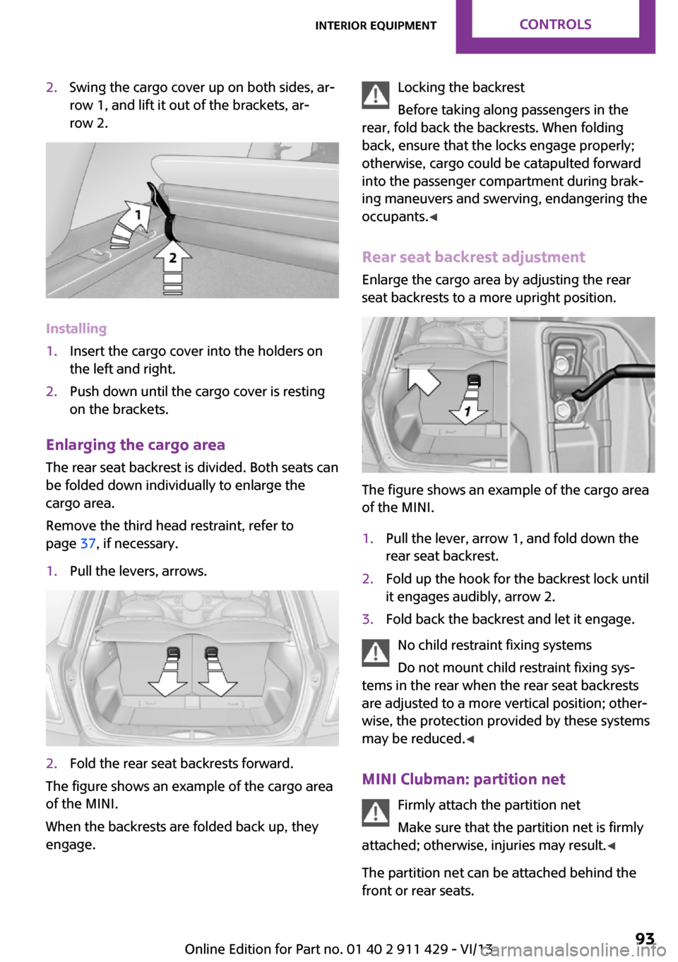
2.Swing the cargo cover up on both sides, ar‐
row 1, and lift it out of the brackets, ar‐
row 2.
Installing
1.Insert the cargo cover into the holders on
the left and right.2.Push down until the cargo cover is resting
on the brackets.
Enlarging the cargo area
The rear seat backrest is divided. Both seats can
be folded down individually to enlarge the
cargo area.
Remove the third head restraint, refer to
page 37, if necessary.
1.Pull the levers, arrows.2.Fold the rear seat backrests forward.
The figure shows an example of the cargo area
of the MINI.
When the backrests are folded back up, they
engage.
Locking the backrest
Before taking along passengers in the
rear, fold back the backrests. When folding
back, ensure that the locks engage properly;
otherwise, cargo could be catapulted forward
into the passenger compartment during brak‐
ing maneuvers and swerving, endangering the
occupants. ◀
Rear seat backrest adjustment
Enlarge the cargo area by adjusting the rear
seat backrests to a more upright position.
The figure shows an example of the cargo area
of the MINI.
1.Pull the lever, arrow 1, and fold down the
rear seat backrest.2.Fold up the hook for the backrest lock until
it engages audibly, arrow 2.3.Fold back the backrest and let it engage.
No child restraint fixing systems
Do not mount child restraint fixing sys‐
tems in the rear when the rear seat backrests
are adjusted to a more vertical position; other‐
wise, the protection provided by these systems
may be reduced. ◀
MINI Clubman: partition net Firmly attach the partition net
Make sure that the partition net is firmly
attached; otherwise, injuries may result. ◀
The partition net can be attached behind the
front or rear seats.
Seite 93Interior equipmentControls93
Online Edition for Part no. 01 40 2 911 429 - VI/13
Page 94 of 210
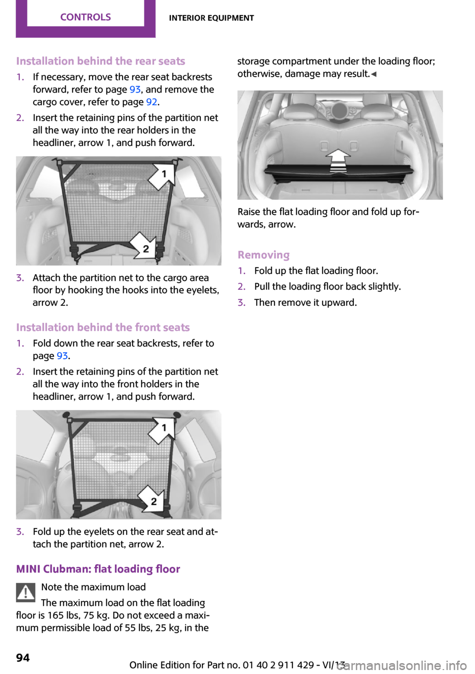
Installation behind the rear seats1.If necessary, move the rear seat backrests
forward, refer to page 93, and remove the
cargo cover, refer to page 92.2.Insert the retaining pins of the partition net
all the way into the rear holders in the
headliner, arrow 1, and push forward.3.Attach the partition net to the cargo area
floor by hooking the hooks into the eyelets,
arrow 2.
Installation behind the front seats
1.Fold down the rear seat backrests, refer to
page 93.2.Insert the retaining pins of the partition net
all the way into the front holders in the
headliner, arrow 1, and push forward.3.Fold up the eyelets on the rear seat and at‐
tach the partition net, arrow 2.
MINI Clubman: flat loading floor
Note the maximum load
The maximum load on the flat loading
floor is 165 lbs, 75 kg. Do not exceed a maxi‐
mum permissible load of 55 lbs, 25 kg, in the
storage compartment under the loading floor;
otherwise, damage may result. ◀
Raise the flat loading floor and fold up for‐
wards, arrow.
Removing
1.Fold up the flat loading floor.2.Pull the loading floor back slightly.3.Then remove it upward.Seite 94ControlsInterior equipment94
Online Edition for Part no. 01 40 2 911 429 - VI/13
Page 95 of 210
Storage compartmentsVehicle equipment
This chapter describes all series equipment as
well as country-specific and special equipment
offered for this model series.Therefore, it also
describes equipment that may not be found in
your vehicle, for instance due to the selected
special equipment or the country version. This
also applies to safety-related functions and sys‐
tems.
Notes No loose objects in the passenger com‐partment
Do not stow any objects in the passenger com‐
partment without securing them; otherwise,
they may present a danger to occupants for in‐
stance during braking and avoidance maneu‐
vers. ◀
No non-slip mats on the dashboard
Do not use non-slip materials, such as
non-slip mats, on the dashboard, or it could be
damaged by the substances in the materials. ◀
Storage compartments
Interior▷Glove compartment, refer to page 95.▷Center armrest, refer to page 96.▷Storage compartment on the passenger
side, refer to page 96.▷Compartments in the center console.▷Compartments in the doors.▷Compartments next to the rear seats.▷Nets on the back of the front seat backrests
and in the front passenger footwell.▷Cupholder, refer to page 91.▷Clothes hooks, refer to page 96.
Cargo area
▷Net on the cargo area floor.▷Lashing eyes, refer to page 105.▷Umbrella holder in front of the warning tri‐
angle under the loading edge.▷MINI Clubman: storage compartment under
the flat loading floor, refer to page 94.▷MINI Clubman: storage compartment in the
split door.▷MINI Clubman: multi-function hooks on the
left and right on the cargo area side walls.
Glove compartment
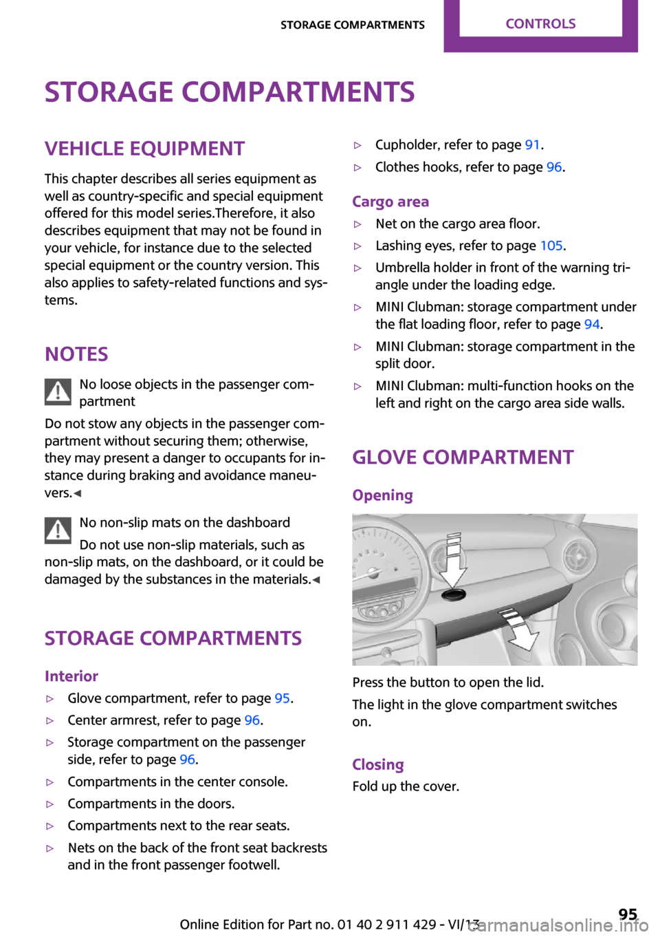
Opening
Press the button to open the lid.
The light in the glove compartment switches
on.
Closing Fold up the cover.
Seite 95Storage compartmentsControls95
Online Edition for Part no. 01 40 2 911 429 - VI/13
Page 96 of 210
Close the glove compartment again im‐
mediately
Close the glove compartment immediately after
use while driving; otherwise, injury may occur
during accidents. ◀
Ventilation Depending on the vehicle's equipment, the
glove compartment can be ventilated and, if
the cooling function is switched on, cooled.
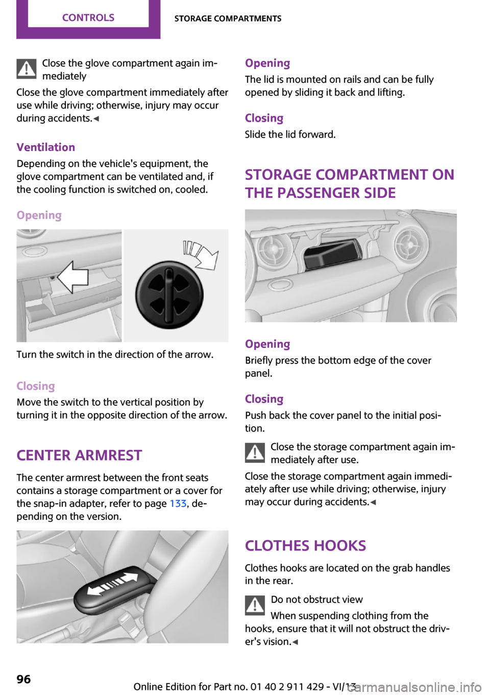
Opening
Turn the switch in the direction of the arrow.
ClosingMove the switch to the vertical position by
turning it in the opposite direction of the arrow.
Center armrest The center armrest between the front seats
contains a storage compartment or a cover for
the snap-in adapter, refer to page 133, de‐
pending on the version.
Opening
The lid is mounted on rails and can be fully
opened by sliding it back and lifting.
ClosingSlide the lid forward.
Storage compartment on
the passenger side
Opening
Briefly press the bottom edge of the cover
panel.
ClosingPush back the cover panel to the initial posi‐
tion.
Close the storage compartment again im‐
mediately after use.
Close the storage compartment again immedi‐
ately after use while driving; otherwise, injury
may occur during accidents. ◀
Clothes hooks Clothes hooks are located on the grab handles
in the rear.
Do not obstruct view
When suspending clothing from the
hooks, ensure that it will not obstruct the driv‐
er's vision. ◀
Seite 96ControlsStorage compartments96
Online Edition for Part no. 01 40 2 911 429 - VI/13
Page 97 of 210

No heavy objects
Do not hang heavy objects from the
hooks; otherwise, they may present a danger
to passengers during braking and evasive ma‐
neuvers. ◀
Connection for an exter‐
nal audio device
This can be used to connect an external audio
device, such as a CD or MP3 player.
Radio MINI Boost CD, refer to page 120.
Seite 97Storage compartmentsControls97
Online Edition for Part no. 01 40 2 911 429 - VI/13
Page 98 of 210
DRIVE ME.
Online Edition for Part no. 01 40 2 911 429 - VI/13
Page 99 of 210
At a glanceControlsDriving tipsEntertainmentCommunicationMobilityReferenceOnline Edition for Part no. 01 40 2 911 429 - VI/13
Page 100 of 210
Things to remember when drivingVehicle equipmentThis chapter describes all series equipment as
well as country-specific and special equipment
offered for this model series.Therefore, it also
describes equipment that may not be found in
your vehicle, for instance due to the selected
special equipment or the country version. This
also applies to safety-related functions and sys‐
tems.
Breaking-in period General information Moving parts need to be broken in to adjust to
each other.
The following instructions will help achieve a
long vehicle life and good economy.
Engine and differential
Always obey all official speed limits.
Up to 1,200 miles/2,000 kmDrive at various engine and vehicle speeds, but
do not exceed:▷For a gasoline engine, 4,500 rpm and
100 mph/160 km/h.
Avoid full-throttle operation and use of the
transmission's kickdown mode for the initial
miles.
From 1,200 miles/2,000 km
The engine and vehicle speed can gradually be
increased.
Tires Due to technical factors associated with their
manufacture, tires do not achieve their full trac‐
tion potential until after an initial breaking-in
period.
Drive conservatively for the first
200 miles/300 km.
Brake system Brakes require an initial break-in period of ap‐
prox. 300 miles/500 km to achieve optimized
contact and wear patterns between brake pads
and discs. Drive cautiously during this break-in
period.
Clutch
The clutch requires an initial break-in period of
approx. 300 miles/500 km to function at an op‐ timal level.
During this break-in period, engage the clutch
gently.
Following part replacementThe same breaking in procedures should be ob‐
served if any of the components mentioned
above have to be renewed in the course of the
vehicle's operating life.
General driving notes
Ground clearance Ensure adequate ground clearance
Ensure adequate ground clearance, e.g.,
when driving into underground garages, when
driving over curbs, or when driving in winter;
otherwise, damage may occur to the vehicle. ◀Seite 100Driving tipsThings to remember when driving100
Online Edition for Part no. 01 40 2 911 429 - VI/13