fog lights MINI Clubman 2016 (Mini Connected) User Guide
[x] Cancel search | Manufacturer: MINI, Model Year: 2016, Model line: Clubman, Model: MINI Clubman 2016Pages: 246, PDF Size: 5.21 MB
Page 127 of 246

Malfunction
A Check Control message is displayed if the sys‐
tem fails or was automatically deactivated.
The system may not be fully functional in the
following situations:
▷When an object was not correctly detected.▷In heavy fog, rain, sprayed water or snow‐
fall.
▷In tight curves.▷If the field of view of the camera or the
front windshield are dirty or covered.
▷When driving toward bright lights.▷Up to 20 seconds after the start of the en‐
gine, via the Start/Stop button.
▷During calibration of the camera immedi‐
ately after vehicle delivery.
Cruise control
The concept
The system is functional at speeds beginning at
approx. 20 mph/30 km/h.
It maintains the speed that was set using the
control elements on the steering wheel.
The system brakes on downhill gradients if en‐
gine braking is insufficient.
Information
WARNING
The system does not relieve from the per‐
sonal responsibility to correctly assess the traf‐
fic situation. Based on the limits of the system,
it cannot independently react to all traffic situa‐
tions. There is risk of an accident. Adjust the
driving style to the traffic conditions. Watch
traffic closely and actively interfere in the re‐
spective situations.◀
WARNING
The use of the system can lead to an in‐
creased risk of accidents in the following situa‐
tions:
▷On winding roads.▷In heavy traffic.▷On slippery roads, in fog, snow or rain, or
on a loose road surface.
There is risk of accidents or risk of property
damage. Only use the system if driving at con‐
stant speed is possible.◀
General information
Depending on the driving program, refer to
page 119, set, the characteristics of the cruise
control in particular areas can change.
Overview
Buttons on the steering wheel
Press buttonFunctionCruise control on/offStore speedPausing cruise control
Continue cruise control with the
last setting
Increasing, maintaining or storing
the speed
Reducing, maintaining or storing
the speed
Controls
Switching on
Press button on the steering wheel.
Seite 127Driving comfortCONTROLS127
Online Edition for Part no. 01 40 2 964 571 - X/15
Page 205 of 246

Front lights, bulb replacement
Overview
Halogen headlights
1Low beams/high beams2Turn signal
LED headlights
1Daytime running lights2Low beams/high beams3Turn signalBug light1Parking lights2Daytime running lights3Fog lights
LED bug light
1Parking lights2Fog lights
LED low beams/LED high beams
Follow the general instructions on lights and
bulbs, refer to page 204.
The lights feature LED technology. In the case
of a malfunction, contact a dealer’s service cen‐
ter or another qualified service center or repair
shop.
Halogen low beams/halogen high
beams
Follow the general instructions on lights and
bulbs, refer to page 204.
Seite 205Replacing componentsMOBILITY205
Online Edition for Part no. 01 40 2 964 571 - X/15
Page 207 of 246
LED parking lights/LED fog lights
Follow the general instructions on lights and
bulbs, refer to page 204.
The lights feature LED technology. In the case
of a malfunction, contact a dealer’s service cen‐
ter or another qualified service center or repair
shop.
Parking lights/fog lights/daytime
running lights
Follow the general instructions on lights and
bulbs, refer to page 204.
Bulbs:
▷Parking lights for halogen headlights: W5W
Parking lights for LED headlights: W5W NBV
▷Daytime running light: PSX24W▷Fog lamp: H8
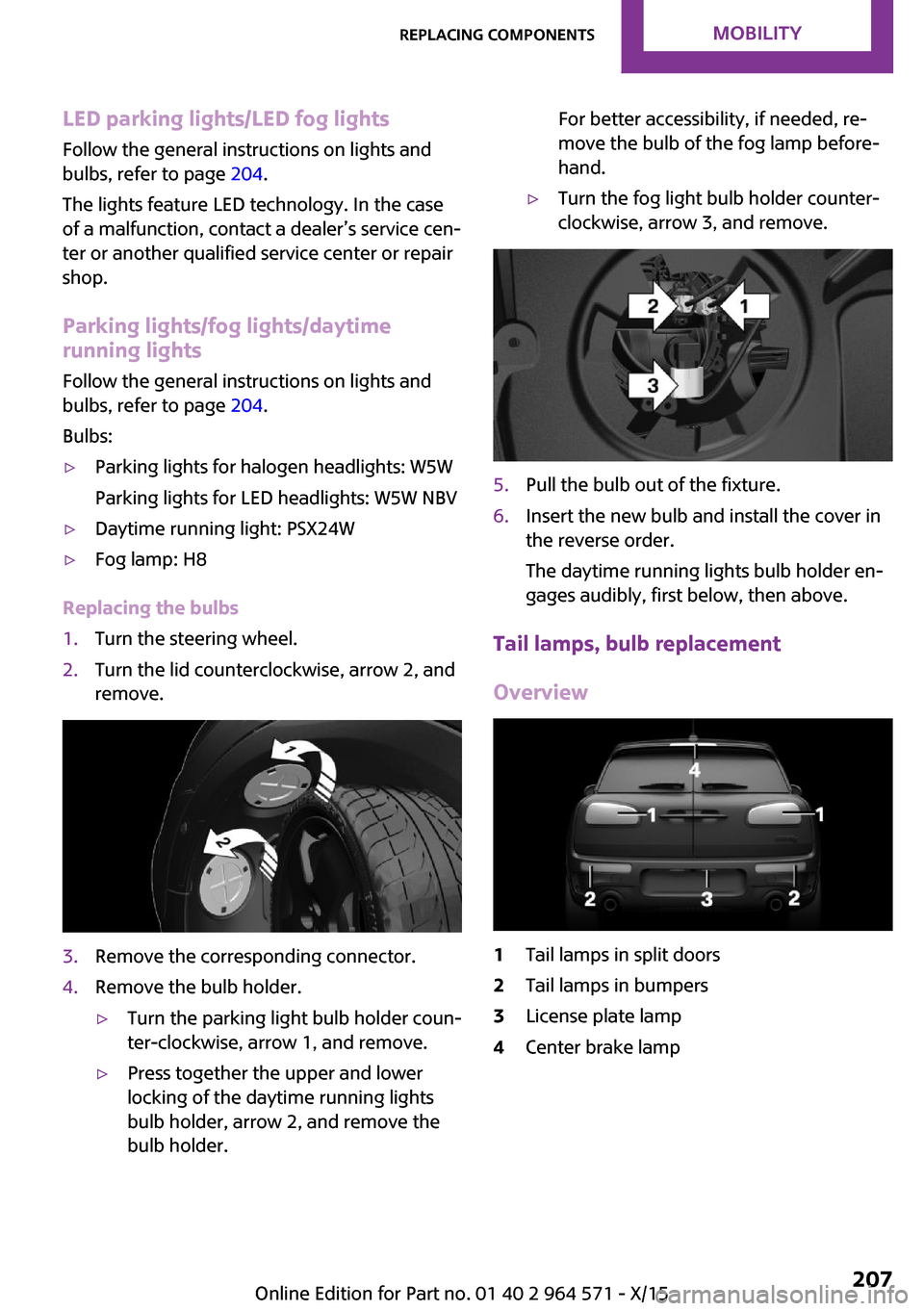
Replacing the bulbs
1.Turn the steering wheel.2.Turn the lid counterclockwise, arrow 2, and
remove.
3.Remove the corresponding connector.4.Remove the bulb holder.▷Turn the parking light bulb holder coun‐
ter-clockwise, arrow 1, and remove.
▷Press together the upper and lower
locking of the daytime running lights
bulb holder, arrow 2, and remove the
bulb holder.
For better accessibility, if needed, re‐
move the bulb of the fog lamp before‐
hand.
▷Turn the fog light bulb holder counter-
clockwise, arrow 3, and remove.
5.Pull the bulb out of the fixture.6.Insert the new bulb and install the cover in
the reverse order.
The daytime running lights bulb holder en‐
gages audibly, first below, then above.
Tail lamps, bulb replacement
Overview
1Tail lamps in split doors2Tail lamps in bumpers3License plate lamp4Center brake lampSeite 207Replacing componentsMOBILITY207
Online Edition for Part no. 01 40 2 964 571 - X/15
Page 208 of 246

Tail lamps in split doors1Turn signal2Tail lamps3Rear fog lamp4Reversing lights
LED tail lights in the split doors
1Turn signal2Tail lamps3Rear fog lamp4Reversing lightsTail lamps in bumpers1Tail lamps/brake lights2Turn signal
In addition, the tail lamps in the bumper as‐
sume the functions of tail lamp and turn sig‐
nals, if the split doors are open.
Tail lamps in split doors
Follow the general instructions on lights and
bulbs, refer to page 204.
Turn signals/tail lamps
Bulbs: P21W/W5W
1.Opening split doors, refer to page 41.2.Remove left or right cover. If necessary, it is
then possible to pry the cover off using a
screwdriver or a similar plastic tool.
3.Press the latches together upward, arrow 1,
and remove the bulb holder.
Seite 208MOBILITYReplacing components208
Online Edition for Part no. 01 40 2 964 571 - X/15
Page 209 of 246
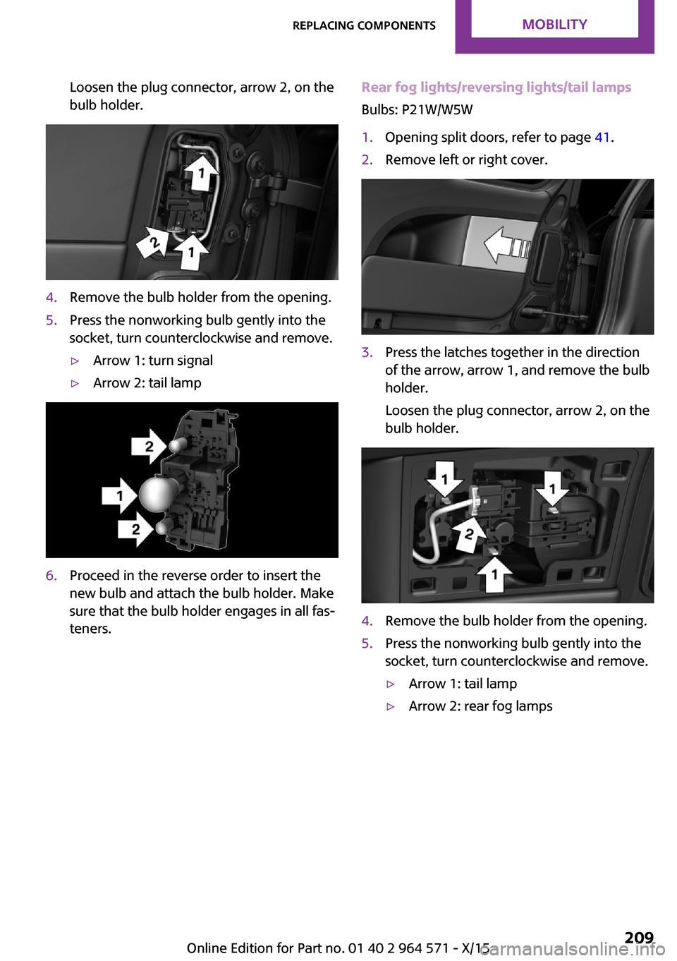
Loosen the plug connector, arrow 2, on the
bulb holder.
4.Remove the bulb holder from the opening.5.Press the nonworking bulb gently into the
socket, turn counterclockwise and remove.
▷Arrow 1: turn signal▷Arrow 2: tail lamp6.Proceed in the reverse order to insert the
new bulb and attach the bulb holder. Make
sure that the bulb holder engages in all fas‐
teners.
Rear fog lights/reversing lights/tail lamps
Bulbs: P21W/W5W
1.Opening split doors, refer to page 41.2.Remove left or right cover.3.Press the latches together in the direction
of the arrow, arrow 1, and remove the bulb
holder.
Loosen the plug connector, arrow 2, on the
bulb holder.
4.Remove the bulb holder from the opening.5.Press the nonworking bulb gently into the
socket, turn counterclockwise and remove.
▷Arrow 1: tail lamp▷Arrow 2: rear fog lampsSeite 209Replacing componentsMOBILITY209
Online Edition for Part no. 01 40 2 964 571 - X/15
Page 239 of 246
Front-end collision warning
with City Braking func‐
tion 111
Front fog lights 99
Front-seat passenger airbags,
automatic deactivation 103
Front-seat passenger airbags,
indicator lamp 103
FTM Flat Tire Monitor 108
Fuel 180
Fuel consumption, see Aver‐
age fuel consumption 89
Fuel filler flap 178
Fuel gauge 84
Fuel lid 178
Fuel quality 180
Fuel recommendation 180
Fuel, tank capacity 230
Fuse 214
G
Garage door opener, see Uni‐
versal Integrated Remote
Control 146
Gasoline 180
Gear change, Steptronic trans‐
mission 75
Gear shift indicator 86
General driving notes 163
Glare shield 150
Glass sunroof, refer to Panor‐
amic glass sunroof 47
Glove compartment 155
GREEN Mode 169
GREEN Mode, bonus
range 171
GREEN Mode driving style
analysis 173
GREEN Mode indicator 169
GREEN - program, driving dy‐
namics 119
GREEN tip 171
Gross vehicle weight, ap‐
proved 229
Ground clearance 164
H
Halogen headlights 205
Handbrake, see Parking
brake 68
Hand-held transmitter, alter‐
nating code 147
Hazard warning flashers 216
Head airbag 101
Headlight control, auto‐
matic 97
Headlight courtesy delay fea‐
ture 97
Headlight flasher 71
Headlight glass 204
Headlights, care 222
Head restraints 50
Head restraints, front 54
Head restraints, rear 55
Head-up Display 93
Head-up Display, standard
view 94
Heavy cargo, stowing 166
High-beam Assistant 98
High beams 71
High beams/low beams, see
High-beam Assistant 98
Hills 164
Hill start assistant, see Drive-
off assistant 120
Holder for beverages 156
Homepage 6
Hood 193
Horn 14
Hot exhaust system 163
HUD Head-up Display 93
Hydroplaning 163
I
Ice warning, see External tem‐
perature warning 84
Icy roads, see External tem‐
perature warning 84
Identification marks, tires 184
Identification number, see ve‐
hicle identification num‐
ber 10
Ignition key, see Remote con‐
trol 34
Ignition off 64
Ignition on 64
Illuminated ring, central in‐
strument cluster 92
Indication of a flat
tire 105, 108
Indicator lamp, see Check
Control 80
Individual air distribu‐
tion 140, 143
Individual settings, see Per‐
sonal Profile 36
Inflation pressure, tires 182
Inflation pressure warning,
tires 108
Info display, refer to On-Board
computer 88
Information 6
Initialize, Tire Pressure Moni‐
tor TPM 105
Initializing, Flat Tire Monitor
FTM 108
Instrument cluster 79
Instrument cluster, electronic
displays 80
Instrument lighting 99
Integrated key 34
Integrated Owner's Manual in
the vehicle 29
Intelligent Safety 110
Intensity, AUTO program 143
Interior equipment 146
Interior lights 99
Interior lights during unlock‐
ing 37
Interior lights with the vehicle
locked 38
Interior mirror, automatic
dimming feature 59
Interior mirror, manually dim‐
mable 59
Seite 239Everything from A to ZREFERENCE239
Online Edition for Part no. 01 40 2 964 571 - X/15
Page 241 of 246
MINI Motorer’s Guide app 6
Minimum tread, tires 186
Mirror memory 56
Mirrors 57
Mobile communication devi‐
ces in the vehicle 163
Mobility System 189
Mode, GREEN Mode 169
Modifications, technical, refer
to Own Safety 7
Moisture in headlight 204
Monitor, refer to Control Dis‐
play 18
Mounting of child restraint
systems 61
Multifunction steering wheel,
buttons 14
Multimedia, refer to
Integrated Owner's Manual
N
Navigation, refer to Integrated
Owner's Manual
Neck restraints, front, see
Head restraints 54
Neck restraints, rear, see
Head restraints 55
New wheels and tires 187
No-touch opening of the split
doors 42
O
OBD Onboard Diagnos‐
tics 202
Obstacle marking, rearview
camera 133
Octane rating, see Recom‐
mended fuel grade 180
Odometer 84
Office, refer to Integrated
Owner's Manual
Oil 195
Oil, adding 196
Oil additives 197
Oil change 197
Oil change interval, service re‐
quirements 85
Oil filler neck 196
Oil types, alternative 197
Oil types, suitable 197
Old batteries, disposal 214
On-board computer 88
On-board computer, refer to
On-board computer 88
Onboard Diagnostics
OBD 202
Onboard monitor 18
Onboard monitor operating
concept 18
Onboard vehicle tool kit 203
Opening/closing via door
lock 39
Opening/closing with remote
control 37
Open the split doors with no-
touch activation 42
Operating menus, onboard
monitor 18
Optional equipment, standard
equipment 7
Outside air, see Automatic re‐
circulated-air control 143
Own safety 7
P
Paint, vehicle 222
Panoramic glass sunroof 47
Parallel parking assistant 134
Park Distance Control
PDC 129
Parked-car ventilation 144
Parked vehicle, condensa‐
tion 164
Parking aid, see PDC 129
Parking assistant 134
Parking brake 68
Parking lights 96
Parts and accessories 8
Passenger side mirror, tilting
downward 58
Pathway lines, rearview cam‐
era 133
PDC Park Distance Con‐
trol 129
Performance Control 118
Personal Profile 36
Person warning with City light
braking function 114
Phone, refer to Integrated
Owner's Manual
Pinch protection system, glass
sunroof 48
Pinch protection system, win‐
dows 46
Plastic, care 223
PostCrash 116
Power failure 214
Power windows 46
Prescribed engine oil
types 197
Pressure, tire air pressure 182
Pressure warning, tires 108
Profile, see Personal Pro‐
file 36
Protective function, glass sun‐
roof 48
Protective function, win‐
dows 46
Push-and-turn switch, see
Controller 19
R
Radiator fluid 199
Radio-operated key, see Re‐
mote control 34
Radio ready state 64
Radio, refer to Integrated
Owner's Manual
Rain sensor 72
Rear fog lights 99
Rear lights 207
Rearview camera 132
Rearview mirror 57
Seite 241Everything from A to ZREFERENCE241
Online Edition for Part no. 01 40 2 964 571 - X/15