remote start MINI Clubman 2016 (Mini Connected) User Guide
[x] Cancel search | Manufacturer: MINI, Model Year: 2016, Model line: Clubman, Model: MINI Clubman 2016Pages: 246, PDF Size: 5.21 MB
Page 69 of 246
In order to ensure that the vehicle is secured
against rolling away, observe the following:
▷Set the parking brake.▷On uphill grades or on a slope, turn the
front wheels in the direction of the curb.
▷On uphill grades or on a slope, also secure
the vehicle, for example with a wheel
chock.◀
WARNING
Unattended children or animals can move
the vehicle and endanger themselves and traf‐
fic, for example with the following actions:
▷Pressing the Start/Stop button.▷Releasing the parking brake.▷Opening and closing of doors or windows.▷Engaging selector lever position N.▷Using vehicle equipment.
There is risk of accidents or injuries. Do not
leave children or animals unattended in the ve‐
hicle. Carry remote control along when exiting
and lock the vehicle.◀
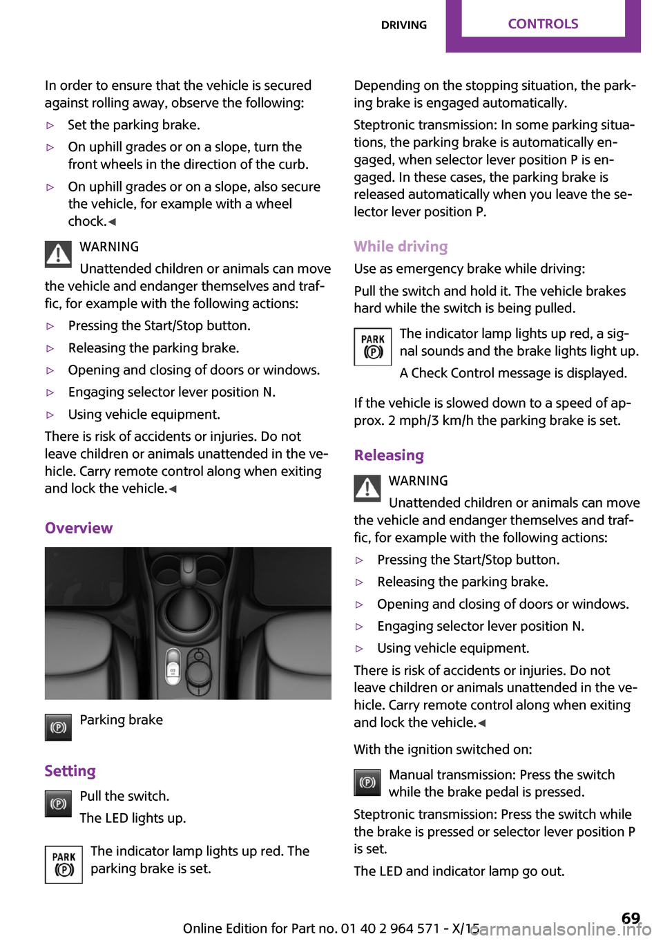
Overview
Parking brake
Setting
Pull the switch.
The LED lights up.
The indicator lamp lights up red. The
parking brake is set.
Depending on the stopping situation, the park‐
ing brake is engaged automatically.
Steptronic transmission: In some parking situa‐
tions, the parking brake is automatically en‐
gaged, when selector lever position P is en‐
gaged. In these cases, the parking brake is
released automatically when you leave the se‐
lector lever position P.
While driving
Use as emergency brake while driving:
Pull the switch and hold it. The vehicle brakes
hard while the switch is being pulled.
The indicator lamp lights up red, a sig‐
nal sounds and the brake lights light up.
A Check Control message is displayed.
If the vehicle is slowed down to a speed of ap‐
prox. 2 mph/3 km/h the parking brake is set.
Releasing
WARNING
Unattended children or animals can move
the vehicle and endanger themselves and traf‐
fic, for example with the following actions:
▷Pressing the Start/Stop button.▷Releasing the parking brake.▷Opening and closing of doors or windows.▷Engaging selector lever position N.▷Using vehicle equipment.
There is risk of accidents or injuries. Do not
leave children or animals unattended in the ve‐
hicle. Carry remote control along when exiting
and lock the vehicle.◀
With the ignition switched on:
Manual transmission: Press the switch
while the brake pedal is pressed.
Steptronic transmission: Press the switch while
the brake is pressed or selector lever position P
is set.
The LED and indicator lamp go out.
Seite 69DrivingCONTROLS69
Online Edition for Part no. 01 40 2 964 571 - X/15
Page 147 of 246

for approximately 20 seconds until the LED
on the interior rearview mirror flashes. This
erases all programming of the buttons on
the interior rearview mirror.
3.Hold the hand-held transmitter for the sys‐
tem to be controlled approx. 1 to 3 in‐
ches/2.5 to 8 cm away from the buttons of
the interior rearview mirror. The required
distance depends on the manual transmit‐
ter.
4.Simultaneously press and hold the button
of the desired function on the hand-held
transmitter and the button to be program‐
med on the interior rearview mirror. The
LED on the interior rearview mirror will be‐
gin flashing slowly.
5.Release both buttons as soon as the LED
flashes more rapidly. The LED flashing
faster indicates that the button on the inte‐
rior rearview mirror has been programmed.
If the LED does not flash faster after at least
60 seconds, change the distance between
the interior rearview mirror and the hand-
held transmitter and repeat the step. Sev‐
eral more attempts at different distances
may be necessary. Wait at least 15 seconds
between attempts.
Canada: if programming with the hand-
held transmitter was interrupted, hold
down the interior rearview mirror button
and repeatedly press and release the hand-
held transmitter button for 2 seconds.
6.To program other functions on other but‐
tons, repeat steps 3 to 5.
The systems can be controlled using the interior
rearview mirror buttons.
Special feature of the alternating-code
wireless system
If you are unable to operate the system after
repeated programming, please check if the sys‐
tem to be controlled features an alternating-
code radio system.
Read the system's operating manual, or press
the programmed button on the interior rear‐
view mirror longer. If the LED on the interior
mirror starts flashing rapidly and then stays lit
constantly for 2 seconds, the system features
an alternating-code radio system. Flashing and
continuous illumination of the LED will repeat
for approximately 20 seconds.
For systems with an alternating-code radio sys‐
tem, the universal remote control and the sys‐
tem also have to be synchronized.
Please read the operating manual to find out
how to synchronize the system.
Synchronizing is easier with the aid of a second
person.
Synchronizing the universal remote control
with the system:
1.Park the vehicle within range of the re‐
mote-controlled system.
2.Program the relevant button on the interior
rearview mirror as described.
3.Locate and press the synchronizing button
on the system being programmed. You
have approx. 30 seconds for the next step.
4.Hold down the programmed button on the
interior rearview mirror for approximately
3 seconds and then release it. If necessary,
repeat this step up to three times in order
to finish synchronization. Once synchroni‐
zation is complete, the programmed func‐
tion will be carried out.
Reprogramming individual buttons
1.Switch on the ignition.2.Press and hold the interior rearview mirror
button to be programmed.
3.As soon as the interior rearview mirror LED
starts flashing slowly, hold the hand-held
transmitter for the system to be controlled
approx. 1 to 3 inches/2.5 to 8 cm away
from the buttons of the interior rearview
mirror. The required distance depends on
the manual transmitter.
Seite 147Interior equipmentCONTROLS147
Online Edition for Part no. 01 40 2 964 571 - X/15
Page 148 of 246

4.Likewise, press and hold the button of the
desired function on the hand-held trans‐
mitter.
5.Release both buttons as soon as the interior
rearview mirror LED flashes more rapidly.
The LED flashing faster indicates that the
button on the interior rearview mirror has
been programmed. The system can then be
controlled by the button on the interior
rearview mirror.
If the LED does not flash faster after at least
60 seconds, change the distance and re‐
peat the step. Several more attempts at dif‐
ferent distances may be necessary. Wait at
least 15 seconds between attempts.
Canada: if programming with the hand-
held transmitter was interrupted, hold
down the interior rearview mirror button
and repeatedly press and release the hand-
held transmitter button for 2 seconds.
Controls
WARNING
Body parts can be jammed when operat‐
ing remote-controlled systems, for example the
garage door, using the integrated universal re‐
mote control. There is risk of injuries or risk of
property damage. Make sure that the area of
movement of the respective system is clear
during programming and operation. Also follow
the safety instructions of the hand-held trans‐
mitter.◀
The system, such as the garage door, can be
operated using the button on the interior rear‐
view mirror while the engine is running or
when the ignition is started. To do this, hold
down the button within receiving range of the
system until the function is activated. The inte‐
rior rearview mirror LED stays lit while the wire‐
less signal is being transmitted.
Deleting stored functions
Press and hold the left and right button on the
interior rearview mirror simultaneously for ap‐
proximately 20 seconds until the LED flashes
rapidly. All stored functions will be deleted. The
functions cannot be deleted individually.
Digital compass
Overview
1Control button2Mirror display
Mirror display
The point of the compass is displayed in the
mirror when driving straight.
Operating concept
Various functions can be called up by pressing
the control button with a pointed object, such
as the tip of a ballpoint pen or similar object.
The following setting options are displayed in
succession, depending on how long the control
button is pressed:
▷Pressed briefly: turns display on/off.▷3 to 6 seconds: compass zone setting.▷6 to 9 seconds: compass calibration.▷9 to 12 seconds: left/right-hand steering
setting.
▷12 to 15 seconds: language setting.
Setting the compass zones
Sets the particular compass zones on the vehi‐
cle so that the compass operates correctly; re‐
fer to World map with compass zones.
Seite 148CONTROLSInterior equipment148
Online Edition for Part no. 01 40 2 964 571 - X/15
Page 150 of 246

Settings are stored automatically after approxi‐
mately 10 seconds.
Sun visor
Glare shield
Fold the sun visor down or up.
Vanity mirror
A vanity mirror is located in the sun visor be‐
hind a cover.
When the cover is opened, the mirror lighting
switches on.
Ashtray/cigarette
lighter
Overview
The ashtray is located in one of the frontal cup
holders, the cigarette lighter above it in the
center console.
Ashtray
In order to empty the ashtray, remove the ash‐
tray from the cupholder.
Lighter
WARNING
Contact with hot heating elements or the
hot socket of the cigarette lighter can cause
burns. Flammable materials can ignite if the
cigarette lighter falls down or is held against
the respective objects. There is risk of fire and
injuries. Hold the cigarette lighter on its handle.
Make sure that children do not use the ciga‐
rette lighter and do not burn themselves, for
example by carrying the remote control along
when exiting the vehicle.◀
CAUTION
If metal objects fall into the socket, they
can cause a short circuit. There is risk of prop‐
erty damage. Replace the cigarette lighter or
socket cover again after using the socket.◀
Push in the lighter.
The lighter can be removed as
soon as it pops back out.
Connecting electrical de‐
vices
Information
WARNING
Devices and cables in the unfolding area
of the airbags, for example portable navigation
devices, etc., can hinder the unfolding of the
airbag or be thrown around in the car's interior
when unfolding. There is risk of injuries. make
sure that devices and cables are not in the air‐
bag's area of unfolding.◀
CAUTION
Battery chargers for the vehicle battery
can work with high voltages and currents,
which means that the 12 volt on-board net‐
work can be overloaded or damaged. There is
risk of property damage. Only connect battery
chargers for the vehicle battery to the starting
aid terminals in the engine compartment.◀
Seite 150CONTROLSInterior equipment150
Online Edition for Part no. 01 40 2 964 571 - X/15
Page 238 of 246
Direction indicator, see Turn
signals 70
Display, electronic, instrument
cluster 80
Display, engine tempera‐
ture 89
Display lighting, see Instru‐
ment lighting 99
Displays 79
Displays, cleaning 224
Disposal, coolant 200
Disposal, vehicle battery 214
Distance control, see PDC 129
Distance to destination 89
Divided screen view, split
screen 23
Door lock, see Remote con‐
trol 34
Drive mode, GREEN
Mode 169
Drive-off assistant 120
Drive-off assistant, see
DSC 117
Driving Dynamics Control 119
Driving Excitement, SPORT 90
Driving instruction, GREEN
Mode 171
Driving instructions, break-
in 162
Driving mode 119
Driving notes, general 163
Driving stability control sys‐
tems 117
Driving style analysis 173
Driving tips 163
DSC Dynamic Stability Con‐
trol 117
DTC Dynamic Traction Con‐
trol 118
Dynamic Damping Con‐
trol 119
Dynamic Stability Control
DSC 117
Dynamic Traction Control
DTC 118
E
Electronic displays, instrument
cluster 80
Electronic oil measure‐
ment 195
Electronic Stability Program
ESP, see DSC 117
Emergency detection, remote
control 35
Emergency release, fuel filler
flap 178
Emergency start function, en‐
gine start 35
Emergency wheel, compact
wheel, see Emergency
wheel 212
Energy Control 85
Engine, automatic Start/Stop
function 66
Engine, automatic switch-
off 66
Engine compartment 193
Engine compartment, working
in 193
Engine coolant 199
Engine idling when driving,
coasting 172
Engine oil 195
Engine oil, adding 196
Engine oil additives 197
Engine oil change 197
Engine oil filler neck 196
Engine oil types, alterna‐
tive 197
Engine oil types, suitable 197
Engine start during malfunc‐
tion 35
Engine start, jump-start‐
ing 216
Engine start, see Starting the
engine 65
Engine stop 65
Engine temperature, dis‐
play 89
Entering a car wash 221
Equipment, interior 146
Error displays, see Check Con‐
trol 80
ESP Electronic Stability Pro‐
gram, see DSC 117
Exchanging wheels/tires 187
Exhaust system 163
Exterior mirror, automatic
dimming feature 58
Exterior mirrors 57
External start 216
External temperature dis‐
play 84
External temperature warn‐
ing 84
Eyes for securing cargo 166
F
Failure message, see Check
Control 80
False alarm, see Unintentional
alarm 45
Fan, see Air flow 140, 143
Favorites buttons, onboard
monitor 24
Filler neck for engine oil 196
Fine wood, care 223
First-aid kit 216
Flat tire, changing wheels 212
Flat Tire Monitor FTM 108
Flat tire, repairing 188
Flat tire, Tire Pressure Monitor
TPM 104
Flat tire, warning
lamp 105, 108
Flooding 163
Floor carpet, care 224
Floor mats, care 224
Fogged up windows 141
Folding back rear seat back‐
rests 153
Fold-out position, windshield
wipers 73
Foot brake 163
Front airbags 101
Seite 238REFERENCEEverything from A to Z238
Online Edition for Part no. 01 40 2 964 571 - X/15
Page 239 of 246
Front-end collision warning
with City Braking func‐
tion 111
Front fog lights 99
Front-seat passenger airbags,
automatic deactivation 103
Front-seat passenger airbags,
indicator lamp 103
FTM Flat Tire Monitor 108
Fuel 180
Fuel consumption, see Aver‐
age fuel consumption 89
Fuel filler flap 178
Fuel gauge 84
Fuel lid 178
Fuel quality 180
Fuel recommendation 180
Fuel, tank capacity 230
Fuse 214
G
Garage door opener, see Uni‐
versal Integrated Remote
Control 146
Gasoline 180
Gear change, Steptronic trans‐
mission 75
Gear shift indicator 86
General driving notes 163
Glare shield 150
Glass sunroof, refer to Panor‐
amic glass sunroof 47
Glove compartment 155
GREEN Mode 169
GREEN Mode, bonus
range 171
GREEN Mode driving style
analysis 173
GREEN Mode indicator 169
GREEN - program, driving dy‐
namics 119
GREEN tip 171
Gross vehicle weight, ap‐
proved 229
Ground clearance 164
H
Halogen headlights 205
Handbrake, see Parking
brake 68
Hand-held transmitter, alter‐
nating code 147
Hazard warning flashers 216
Head airbag 101
Headlight control, auto‐
matic 97
Headlight courtesy delay fea‐
ture 97
Headlight flasher 71
Headlight glass 204
Headlights, care 222
Head restraints 50
Head restraints, front 54
Head restraints, rear 55
Head-up Display 93
Head-up Display, standard
view 94
Heavy cargo, stowing 166
High-beam Assistant 98
High beams 71
High beams/low beams, see
High-beam Assistant 98
Hills 164
Hill start assistant, see Drive-
off assistant 120
Holder for beverages 156
Homepage 6
Hood 193
Horn 14
Hot exhaust system 163
HUD Head-up Display 93
Hydroplaning 163
I
Ice warning, see External tem‐
perature warning 84
Icy roads, see External tem‐
perature warning 84
Identification marks, tires 184
Identification number, see ve‐
hicle identification num‐
ber 10
Ignition key, see Remote con‐
trol 34
Ignition off 64
Ignition on 64
Illuminated ring, central in‐
strument cluster 92
Indication of a flat
tire 105, 108
Indicator lamp, see Check
Control 80
Individual air distribu‐
tion 140, 143
Individual settings, see Per‐
sonal Profile 36
Inflation pressure, tires 182
Inflation pressure warning,
tires 108
Info display, refer to On-Board
computer 88
Information 6
Initialize, Tire Pressure Moni‐
tor TPM 105
Initializing, Flat Tire Monitor
FTM 108
Instrument cluster 79
Instrument cluster, electronic
displays 80
Instrument lighting 99
Integrated key 34
Integrated Owner's Manual in
the vehicle 29
Intelligent Safety 110
Intensity, AUTO program 143
Interior equipment 146
Interior lights 99
Interior lights during unlock‐
ing 37
Interior lights with the vehicle
locked 38
Interior mirror, automatic
dimming feature 59
Interior mirror, manually dim‐
mable 59
Seite 239Everything from A to ZREFERENCE239
Online Edition for Part no. 01 40 2 964 571 - X/15
Page 240 of 246

Interior motion sensor 45
Interior rearview mirror, com‐
pass 148
Internet site 6
Interval display, service re‐
quirements 85
Interval mode 72
J
Jacking points for the vehicle
jack 212
Joystick, Steptronic transmis‐
sion 75
Jump-starting 216
K
Key/remote control 34
Keyless Go, see Comfort Ac‐
cess 41
Key Memory, see Personal
Profile 36
Kickdown, Steptronic trans‐
mission 75
Knee airbag 102
L
Label on recommended
tires 187
Lamp replacement 204
Lamp replacement, front 205
Lamp replacement, rear 207
Lamp replacement, side 211
Language on Control Dis‐
play 92
Lashing eyes, securing
cargo 166
LATCH child restraint sys‐
tem 62
Launch Control 77
Leather, care 222
LED bug light 205
LED headlights 205
LED ring, central instrument
cluster 92
LEDs, light-emitting di‐
odes 204
Letters and numbers, enter‐
ing 25
Light 96
Light-alloy wheels, care 223
Light-emitting diodes,
LEDs 204
Lighter 150
Lighting 96
Lights and bulbs 204
Light switch 96
Load 166
Loading 165
Lock, door 39
Locking/unlocking via door
lock 39
Locking/unlocking with re‐
mote control 37
Locking, automatic 44
Locking, settings 43
Lock, power window 47
Locks, doors, and windows 63
Low beams 96
Low beams, automatic, see
High-beam Assistant 98
Lower back support 52
Lower back support, mechani‐
cal 51
Luggage rack, refer to Roof-
mounted luggage rack 166
Lumbar support 52
Lumbar support, mechani‐
cal 51
M
Maintenance 201
Maintenance require‐
ments 201
Maintenance, service require‐
ments 85
Maintenance system,
MINI 201
Make-up mirror 150
Malfunction displays, see
Check Control 80
Manual air distribu‐
tion 140, 143
Manual air flow 140, 143
Manual brake, see Parking
brake 68
Manual mode, transmis‐
sion 76
Manual operation, door
lock 39
Manual operation, exterior
mirrors 58
Manual operation, fuel filler
flap 178
Manual operation, Park Dis‐
tance Control PDC 130
Manual operation, rearview
camera 132
Manual transmission 74
Manufacturer of the MINI 7
Marking, run-flat tires 188
Master key, see Remote con‐
trol 34
Maximum cooling 142
Maximum speed, display 86
Maximum speed, winter
tires 188
Measurement, units of 92
Medical kit 216
Memory, seat, mirror 56
Menu in instrument cluster 88
Menus, refer to onboard mon‐
itor operating concept 20
Messages, see Check Con‐
trol 80
Microfilter 141, 144
MID - program, driving dy‐
namics 119
MINI Connected, refer to
Integrated Owner's Manual
MINI maintenance sys‐
tem 201
MINIMALISM Analyser 173
MINIMALISM info 172
Seite 240REFERENCEEverything from A to Z240
Online Edition for Part no. 01 40 2 964 571 - X/15
Page 242 of 246
Rear window de‐
froster 141, 144
Recirculated-air filter 144
Recirculated-air
mode 140, 143
Recommended fuel
grade 180
Recommended tire
brands 187
Refueling 178
Remaining range 85
Remote control/key 34
Remote control, blocking 35
Remote control, malfunc‐
tion 39
Remote control, replacing the
battery 34
Remote control, univer‐
sal 146
Replacement fuse 214
Replacing parts 203
Replacing the battery, remote
control 34
Replacing wheels/tires 187
Reporting safety malfunc‐
tions 10
RES CNCL button, see camera-
based cruise control 121
RES CNCL button, see Cruise
control 127
Reserve warning, see
Range 85
Reset, Tire Pressure Monitor
TPM 105
Retaining straps, securing
cargo 166
Retreaded tires 187
Roadside parking lights 97
RON recommended fuel
grade 180
Roofliner 17
Roof load capacity 229
Roof-mounted luggage
rack 166
RSC Run Flat System Compo‐
nent, see Run-flat tires 188
Rubber components,
care 223
Run-flat tires 188
S
Safe braking 163
Safety belt reminder for driv‐
er's seat and front passenger
seat 54
Safety belts 53
Safety belts, care 224
Safety switch, windows 47
Safety systems, airbags 101
Saving fuel 168
Screen, refer to Control Dis‐
play 18
Screwdriver 203
Sealant 189
Seat and mirror memory 56
Seat belts, see Safety belts 53
Seat heating, front 52
Seating position for chil‐
dren 60
Seats 50
Selection list in instrument
cluster 88
Selector lever, Steptronic
transmission 75
Sensors, care 224
Service and warranty 8
Service requirements, Condi‐
tion Based Service CBS 201
Service requirements, dis‐
play 85
SET button, see camera-based
cruise control 121
SET button, see Cruise con‐
trol 127
Settings, locking/unlocking 43
Settings, mirrors 57
Settings on Control Display 91
Settings, storing for seat, mir‐
ror 56
Shift paddles on the steering
wheel 76
Side airbag 101
Signaling, horn 14
Signals when unlocking 44
Sitting safely 50
Size 228
Slide/tilt glass roof 47
Snow chains 192
Socket 150
Socket, OBD Onboard Diag‐
nostics 202
Spare fuse 214
Spare tire, see Emergency
wheel 212
Speed, average 89
Speed limit detection, on‐
board computer 89
Speed limiter, display 86
Speed Limit Information 86
Speed warning 91
Split Doors 40
Split doors via remote con‐
trol 38
Split screen 23
Sport displays 90
SPORT program, Dynamic
Driving Control 119
Sport program, transmis‐
sion 76
Stability control systems 117
Standard view, Head-up Dis‐
play 94
Start/stop, automatic func‐
tion 66
Start/Stop button 64
Start function during malfunc‐
tion 35
Starting the engine 65
Status control display,
tires 105
Status information, onboard
monitor 23
Status of Owner's Manual 7
Steering wheel, adjusting 59
Steptronic Sport transmission,
see Steptronic transmis‐
sion 75
Seite 242REFERENCEEverything from A to Z242
Online Edition for Part no. 01 40 2 964 571 - X/15
Page 243 of 246
Steptronic transmission 75
Stopping the engine 65
Storage compartments 155
Storage, tires 188
Storing the vehicle 224
Suitable engine oil types 197
Summer tires, tread 186
Sun visor 150
Supplementary text mes‐
sages 83
Switch for Dynamic Driv‐
ing 119
Switch-on times, parked-car
ventilation 145
Switch, see Cockpit 14
Symbols 6
Symbols in the status field 23
T
Tachometer 84
Tailgate, see split doors 40
Tail lamps 207
Technical changes, refer to
Own Safety 7
Technical data 228
Temperature, air condi‐
tioner 140
Temperature, automatic cli‐
mate control 142
Temperature display for exter‐
nal temperature 84
Temperature, engine 89
Tempomat, see camera-based
cruise control 121
Terminal, starting aid 217
Text messages, supplemen‐
tary 83
Theft alarm system, see Alarm
system 44
Thigh support 52
Tilt alarm sensor 45
Time of arrival 89
Tire damage 186
Tire identification marks 184
Tire inflation pressure 182
Tire inflation pressure moni‐
tor, refer to FTM 108
Tire Pressure Monitor
TPM 104
Tires, changing 187
Tire sealant 189
Tires, everything on wheels
and tires 182
Tires, run-flat tires 188
Tire tread 186
Tone, refer to Integrated
Owner's Manual
Tools 203
Total vehicle weight 229
Touchpad 21
Towing 217
Tow-starting 217
TPM Tire Pressure Moni‐
tor 104
Traction control 118
TRACTION drive mode, driving
dynamics 118
Transmission lock, releasing
manually 77
Transmission, manual trans‐
mission 74
Transmission, see Steptronic
transmission 75
Transporting children
safely 60
Tread, tires 186
Triple turn signal activa‐
tion 70
Trip odometer 84
Trip onboard computer 90
Trip recorder, see Trip odome‐
ter 84
Turning circle lines, rearview
camera 133
Turn signal, front 205
Turn signal, side 211
Turn signals, operation 70
Turn signals, rear, bulb re‐
placement 207
U
Unintentional alarm 45
Units of measurement 92
Universal remote control 146
Unlock button, Steptronic
transmission 75
Unlocking/locking via door
lock 39
Unlocking/locking with re‐
mote control 37
Unlocking, settings 43
Updates made after the edito‐
rial deadline 7
Upholstery care 223
USB interface 151
V
Vanity mirror 150
Vehicle battery 213
Vehicle battery, replacing 214
Vehicle, break-in 162
Vehicle care 222
Vehicle features and op‐
tions 7
Vehicle identification num‐
ber 10
Vehicle jack 212
Vehicle paint 222
Vehicle storage 224
Vehicle wash 221
Ventilation 144
Ventilation, see Parked-car
ventilation 144
VIN, see vehicle identification
number 10
Voice activation system 26
W
Warning and indicator lamps,
see Check Control 80
Warning displays, see Check
Control 80
Seite 243Everything from A to ZREFERENCE243
Online Edition for Part no. 01 40 2 964 571 - X/15