air condition MINI Clubman 2016 Owner's Manual (Mini Connected)
[x] Cancel search | Manufacturer: MINI, Model Year: 2016, Model line: Clubman, Model: MINI Clubman 2016Pages: 246, PDF Size: 5.21 MB
Page 7 of 246
▷First possibility.▷Second possibility.
Symbols on vehicle components
Indicates that you should consult the
relevant section of this Owner's Manual for
information on a particular part or assembly.
Vehicle features and op‐
tions
This Owner's Manual describes all models and
all standard, country-specific and optional
equipment that is offered in the model series.
Therefore, in this Owner's Manual, we also de‐
scribe and illustrate features that are not avail‐
able in your vehicle, for example, because of
the selected optional features or the country-
specific version.
This also applies to safety-related functions and
systems.
The respectively applicable country provisions
must be observed when using the respective
features and systems.
For any options and equipment not described
in this Owner's Manual, refer to the Supple‐
mentary Owner's Manuals.
On right-hand drive vehicles, some control ele‐
ments are arranged differently from what is
shown in the illustrations.
Status of the Owner's
Manual
Basic information
The manufacturer of your vehicle pursues a
policy of constant development that is con‐
ceived to ensure that our vehicles continue to
embody the highest quality and safety stan‐
dards. In rare cases, therefore, the features de‐
scribed in this Owner's Manual may differ from
those in your vehicle.
Updates made after the editorial
deadline
Updates made after the editorial deadline can
lead to differences between the printed Own‐
er's Manual and the following Owner's Man‐
uals:
▷Integrated Owner's Manual in the vehicle.▷Online Owner's Manual.▷MINI Motorer’s Guide App.
Information to updates made after the editorial
deadline can be found in the appendix of the
printed Owner's Manual for the vehicle.
Own safety
Manufacturer
The manufacturer of this MINI is Bayerische
Motoren Werke Aktionengesellschaft, BMW AG.
Warranty
Your vehicle is technically configured for the
operating conditions and registration require‐
ments applying in the country of first delivery
also known as homologation. If your vehicle is
to be operated in a different country it might
be necessary to adapt your vehicle to poten‐
tially differing operating conditions and permit
requirements. If your vehicle does not comply
with the homologation requirements in a cer‐
tain country you may not be able to lodge war‐
ranty claims for your vehicle there. Further in‐
formation on warranty is available from a
dealer’s service center.
Maintenance and repairs
Advanced technology, e.g., the use of modern
materials and high-performance electronics,
requires suitable maintenance and repair work.
Seite 7Information7
Online Edition for Part no. 01 40 2 964 571 - X/15
Page 8 of 246
The manufacturer of your vehicle recommends
that you entrust corresponding procedures to a
MINI dealer’s service center. If you choose to
use another service facility, the manufacturer of
your vehicle recommends use of a facility that
performs work, e.g. maintenance and repair,
according to MINI specifications with properly
trained personnel, referred to in this Owner's
Manual as "another qualified service center or
repair shop".
If work is performed improperly, e.g. mainte‐
nance and repair, there is a risk of subsequent
damage and related safety risks.
Parts and accessories
The manufacturer of your vehicle recommends
the use of parts and accessory products ap‐
proved by the manufacturer of the MINI.
Approved parts and accessories, and advice on
their use and installation are available from a
MINI dealer's service center.
MINI parts and accessories were tested by the
manufacturer of the MINI for their safety and
suitability in MINI vehicles.
The manufacturer of your vehicle warrants gen‐
uine MINI parts and accessories.
The manufacturer of your vehicle does not
evaluate whether each individual product from
another manufacturer can be used with MINI
vehicles without presenting a safety hazard,
even if a country-specific official approval was
issued. The manufacturer of your vehicle does
not evaluate whether these products are suita‐
ble for MINI vehicles under all usage conditions.
California Proposition 65 Warning
California laws require us to state the following
warning:
Engine exhaust and a wide variety of automo‐
bile components and parts, including compo‐
nents found in the interior furnishings in a vehi‐
cle, contain or emit chemicals known to the
State of California to cause cancer and birth de‐
fects and reproductive harm. In addition, cer‐
tain fluids contained in vehicles and certain
products of component wear contain or emit
chemicals known to the State of California to
cause cancer and birth defects or other repro‐
ductive harm. Battery posts, terminals and re‐
lated accessories contain lead and lead com‐
pounds. Wash your hands after handling. Used
engine oil contains chemicals that have caused
cancer in laboratory animals. Always protect
your skin by washing thoroughly with soap and
water.
Service and warranty
We recommend that you read this publication
thoroughly. Your vehicle is covered by the fol‐
lowing warranties:
▷New Vehicle Limited Warranty.▷Rust Perforation Limited Warranty.▷Federal Emissions System Defect Warranty.▷Federal Emissions Performance Warranty.▷California Emission Control System Limited
Warranty.
Detailed information about these warranties is
listed in the Service and Warranty Information
Booklet for US models or in the Warranty and
Service Guide Booklet for Canadian models.
Your vehicle has been specifically adapted and
designed to meet the particular operating con‐
ditions and homologation requirements in your
country and continental region in order to de‐
liver the full driving pleasure while the vehicle is
operated under those conditions. If you wish to
operate your vehicle in another country or re‐
gion, you may be required to adapt your vehi‐
cle to meet different prevailing operating con‐
ditions and homologation requirements. You
should also be aware of any applicable war‐
ranty limitations or exclusions for such country
or region. In such case, please contact Cus‐
tomer Relations for further information.
Seite 8Information8
Online Edition for Part no. 01 40 2 964 571 - X/15
Page 9 of 246
Maintenance
Maintain the vehicle regularly to sustain the
road safety, operational reliability and the New
Vehicle Limited Warranty.
Specifications for required maintenance meas‐
ures:
▷MINI Maintenance system▷Service and Warranty Information Booklet
for US models
▷Warranty and Service Guide Booklet for
Canadian models
If the vehicle is not maintained according to
these specifications, this could result in serious
damage to the vehicle. Such damage is not
covered by the MINI New Vehicle Limited War‐
ranty.
Data memory
Many electronic components on your vehicle
are equipped with data memories that tempo‐
rarily or permanently store technical informa‐
tion about the condition of the vehicle, events
and faults. This technical information generally
records the state of a component, a module, a
system or the environment:
▷Operating mode of system components, fill
levels for instance.
▷Status messages for the vehicle and from its
individual components, e.g., wheel rotation
speed/vehicle speed, deceleration, trans‐
verse acceleration.
▷Malfunctions and faults in important system
components, e.g., lights and brakes.
▷Responses by the vehicle to special situa‐
tions such as airbag deployment or engag‐
ing the stability control system.
▷Ambient conditions, such as temperature.
This data is purely technical in nature and is
used to detect and correct faults and to opti‐
mize vehicle functions. Motion profiles over
routes traveled cannot be created from this
data. When service offerings are used, e.g., re‐
pair services, service processes, warranty
claims, quality assurance, this technical infor‐
mation can be read out from the event and
fault memories by employees of a dealer’s
service center or another qualified service cen‐
ter or repair shop, including the manufacturer,
using special diagnostic tools. You can obtain
further information there if you need it. After
an error is corrected, the information in the
fault memory is deleted or overwritten on a
continuous basis.
With the vehicle in use there are situations
where you can associate these technical data
with individuals if combined with other infor‐
mation, e.g., an accident report, damage to the
vehicle, eye witness accounts — possibly with
the assistance of an expert.
Additional functions that are contractually
agreed with the customer - such as vehicle
emergency locating - you can transmit certain
vehicle data from the vehicle.
Event Data Recorder EDR
This vehicle is equipped with an event data re‐
corder EDR. The main purpose of an EDR is to
record, in certain crash or near crash-like situa‐
tions, such as an air bag deployment or hitting
a road obstacle, data that will assist in under‐
standing how a vehicle’s systems performed.
The EDR is designed to record data related to
vehicle dynamics and safety systems for a short
period of time, typically 30 seconds or less.
The EDR in this vehicle is designed to record
such data as:
▷How various systems in your vehicle were
operating.
▷Whether or not the driver and passenger
safety belts were fastened.
▷How far, if at all, the driver was depressing
the accelerator and/or brake pedal.
▷How fast the vehicle was traveling.Seite 9Information9
Online Edition for Part no. 01 40 2 964 571 - X/15
Page 67 of 246
▷The selector lever is in selector lever posi‐
tion D.
▷Brake pedal remains depressed while the
vehicle is stopped.
▷The driver's safety belt is buckled or the
driver's door is closed.
In order to be able to release the brake pedal,
engage lever in position P. The engine remains
off.
To continue driving depress the brake pedal.
When a gear is engaged, the engine starts au‐
tomatically.
The air flow from the air conditioner is reduced
when the engine is switched off.
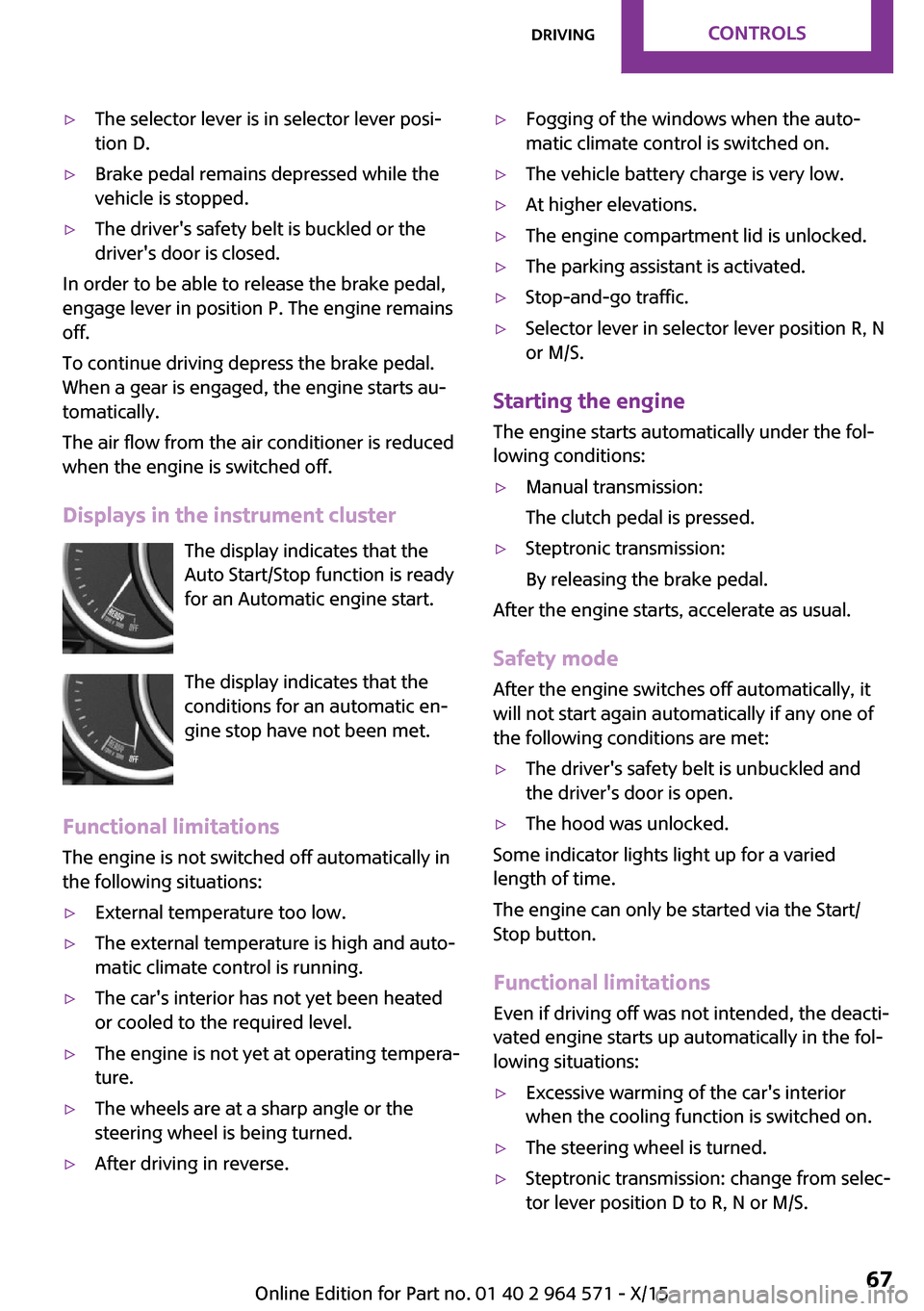
Displays in the instrument cluster
The display indicates that the
Auto Start/Stop function is ready
for an Automatic engine start.
The display indicates that the
conditions for an automatic en‐
gine stop have not been met.
Functional limitations
The engine is not switched off automatically in
the following situations:
▷External temperature too low.▷The external temperature is high and auto‐
matic climate control is running.
▷The car's interior has not yet been heated
or cooled to the required level.
▷The engine is not yet at operating tempera‐
ture.
▷The wheels are at a sharp angle or the
steering wheel is being turned.
▷After driving in reverse.▷Fogging of the windows when the auto‐
matic climate control is switched on.
▷The vehicle battery charge is very low.▷At higher elevations.▷The engine compartment lid is unlocked.▷The parking assistant is activated.▷Stop-and-go traffic.▷Selector lever in selector lever position R, N
or M/S.
Starting the engine
The engine starts automatically under the fol‐
lowing conditions:
▷Manual transmission:
The clutch pedal is pressed.
▷Steptronic transmission:
By releasing the brake pedal.
After the engine starts, accelerate as usual.
Safety mode
After the engine switches off automatically, it
will not start again automatically if any one of
the following conditions are met:
▷The driver's safety belt is unbuckled and
the driver's door is open.
▷The hood was unlocked.
Some indicator lights light up for a varied
length of time.
The engine can only be started via the Start/
Stop button.
Functional limitations
Even if driving off was not intended, the deacti‐
vated engine starts up automatically in the fol‐
lowing situations:
▷Excessive warming of the car's interior
when the cooling function is switched on.
▷The steering wheel is turned.▷Steptronic transmission: change from selec‐
tor lever position D to R, N or M/S.
Seite 67DrivingCONTROLS67
Online Edition for Part no. 01 40 2 964 571 - X/15
Page 81 of 246
be activated if objects are placed on the front
passenger seat.
Make sure that the safety belts are positioned
correctly.
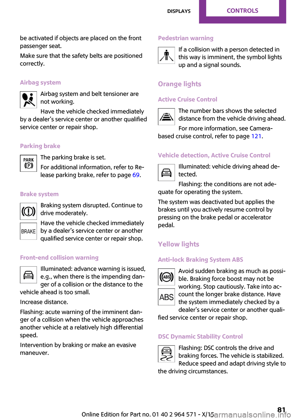
Airbag system
Airbag system and belt tensioner are
not working.
Have the vehicle checked immediately
by a dealer’s service center or another qualified
service center or repair shop.
Parking brake
The parking brake is set.
For additional information, refer to Re‐
lease parking brake, refer to page 69.
Brake system
Braking system disrupted. Continue to
drive moderately.
Have the vehicle checked immediately
by a dealer’s service center or another
qualified service center or repair shop.
Front-end collision warning
Illuminated: advance warning is issued,
e.g., when there is the impending dan‐
ger of a collision or the distance to the
vehicle ahead is too small.
Increase distance.
Flashing: acute warning of the imminent dan‐
ger of a collision when the vehicle approaches
another vehicle at a relatively high differential
speed.
Intervention by braking or make an evasive
maneuver.
Pedestrian warning
If a collision with a person detected in
this way is imminent, the symbol lights
up and a signal sounds.
Orange lights
Active Cruise Control
The number bars shows the selected
distance from the vehicle driving ahead.
For more information, see Camera-
based cruise control, refer to page 121.
Vehicle detection, Active Cruise Control
Illuminated: vehicle driving ahead de‐
tected.
Flashing: the conditions are not ade‐
quate for operating the system.
The system was deactivated but applies the
brakes until you actively resume control by
pressing on the brake pedal or accelerator
pedal.
Yellow lights
Anti-lock Braking System ABS
Avoid sudden braking as much as possi‐
ble. Braking force boost may not be
working. Stop cautiously. Take into ac‐
count the longer brake distance. Have
the system immediately checked by a
dealer’s service center or another quali‐
fied service center or repair shop.
DSC Dynamic Stability Control
Flashing: DSC controls the drive and
braking forces. The vehicle is stabilized.
Reduce speed and adapt driving style to
the driving circumstances.
Seite 81DisplaysCONTROLS81
Online Edition for Part no. 01 40 2 964 571 - X/15
Page 98 of 246
System limits
The automatic headlamp control cannot serve
as a substitute for your personal judgment of
lighting conditions.
E. g. the sensors are unable to detect fog or
hazy weather. To avoid safety risks under these
conditions, you should always switch on the
lights manually.
Daytime running lights
General information
Position of switch: , ,
The daytime running lights light up when the
ignition is switched on. After the ignition is
switched off, the parking lights light up in posi‐
tion .
Activating/deactivating
In some countries, daytime running lights are
mandatory, so it may not be possible to deacti‐
vate the daytime running lights.
On the Control Display:
1. "Settings"2."Lighting"3."Daytime running lamps"
Settings are stored for the remote control cur‐
rently used.
Cornering lamp
General information
Position of switch:
When going around corners, the cornering light
also lights the interior area of the curve. Below
a speed of approx. 25 mph/40 km/h when the
turn signal is switched on and the steering an‐
gle is detected, there is automatic activation.
Malfunction
A Check Control message is displayed.
Cornering light is malfunctioning or has failed.
Have the system immediately checked by a
dealer’s service center or another qualified
service center or repair shop.
High-beam Assistant
The concept
The high-beam Assistant detects other traffic
participants early on and automatically
switches the high beams on or off depending
on the traffic situation. The assistant ensures
that the high beams are switched on, whenever
the traffic situation allows. In the low speed
range, the high beams are not switched on by
the system.
General information
The system responds to light from oncoming
traffic and traffic driving ahead of you, and to
adequate illumination, e.g., in towns and cities.
The driver can intervene at any time and switch
the high beams on and off as usual.
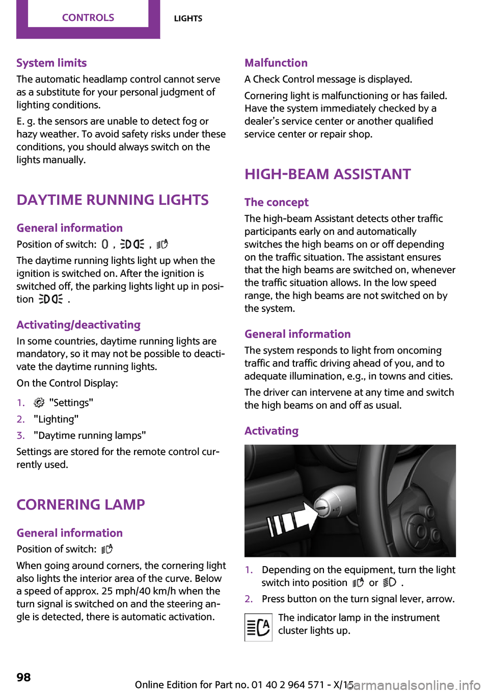
Activating
1.Depending on the equipment, turn the light
switch into position or .
2.Press button on the turn signal lever, arrow.
The indicator lamp in the instrument
cluster lights up.
Seite 98CONTROLSLights98
Online Edition for Part no. 01 40 2 964 571 - X/15
Page 106 of 246

WARNING
A damaged regular tire with low or miss‐
ing tire inflation pressure impacts handling,
such as steering and braking response. Run-flat
tires can maintain limited stability. There is risk
of an accident. Do not continue driving if the
vehicle is not equipped with run-flat tires. Ob‐
serve the hints on run-flat tires and continued
driving with these tires.◀
A low tire inflation pressure might turn on DSC
Dynamic Stability Control.
Actions in the event of a flat tire
Normal tires
1.Identify the damaged tire.
Do this by checking the air pressure in all
four tires.
The tire pressure gauge of the Mobility Sys‐
tem, refer to page 189, can be used for this
purpose.
If the tire inflation pressure in all four tires is
correct, the Tire Pressure Monitor may not
have been initialized. In this case, initialize
the system.
If identification of flat tire damage is not
possible, please contact a dealer’s service
center or another qualified service center or
repair shop.
2.Fix the flat tire using the Mobility System,
refer to page 189.
Use of tire sealant, e.g., the Mobility System,
may damage the TPM wheel electronics. In this
case, have the electronics checked at the next
opportunity and have them replaced if needed.
Run-flat tires
Maximum speed
You may continue driving with a damaged tire
at speeds up to 50 mph/80 km/h.
Continued driving with a flat tire
If continuing to drive with a damaged tire:
1.Avoid sudden braking and steering maneu‐
vers.
2.Do not exceed a speed of 50 mph/80 km/h.3.Check the air pressure in all four tires at the
next opportunity.
If the tire inflation pressure in all four tires is
shown to be correct, it is possible that the
Tire Pressure Monitor did not perform a re‐
set. Then perform the reset.
Possible driving distance with complete loss of
tire inflation pressure:
The possible driving distance after a loss of tire
inflation pressure depends on cargo load, driv‐
ing style and road conditions.
A vehicle with an average load has a possible
driving range of approx. 50 miles/80 km.
A vehicle with a damaged tire reacts differently,
e.g., it has reduced lane stability during brak‐
ing, a longer braking distance and different
self-steering properties. Adjust your driving
style accordingly. Avoid abrupt steering ma‐
neuvers or driving over obstacles, e.g., curbs,
potholes, etc.
Because the possible driving distance depends
on how the vehicle is used during the trip, the
actual distance may be shorter or longer de‐
pending on the driving speed, road conditions,
external temperature, cargo load, etc.
WARNING
Your vehicle handles differently when a
run-flat tire is damaged and has low or missing
tire inflation pressure, for example, your lane
stability is reduced when braking, braking dis‐
tances are longer and the self-steering proper‐
ties will change. There is risk of an accident.
Drive moderately and do not exceed a speed of
50 mph/80 km/h.◀
Seite 106CONTROLSSafety106
Online Edition for Part no. 01 40 2 964 571 - X/15
Page 109 of 246
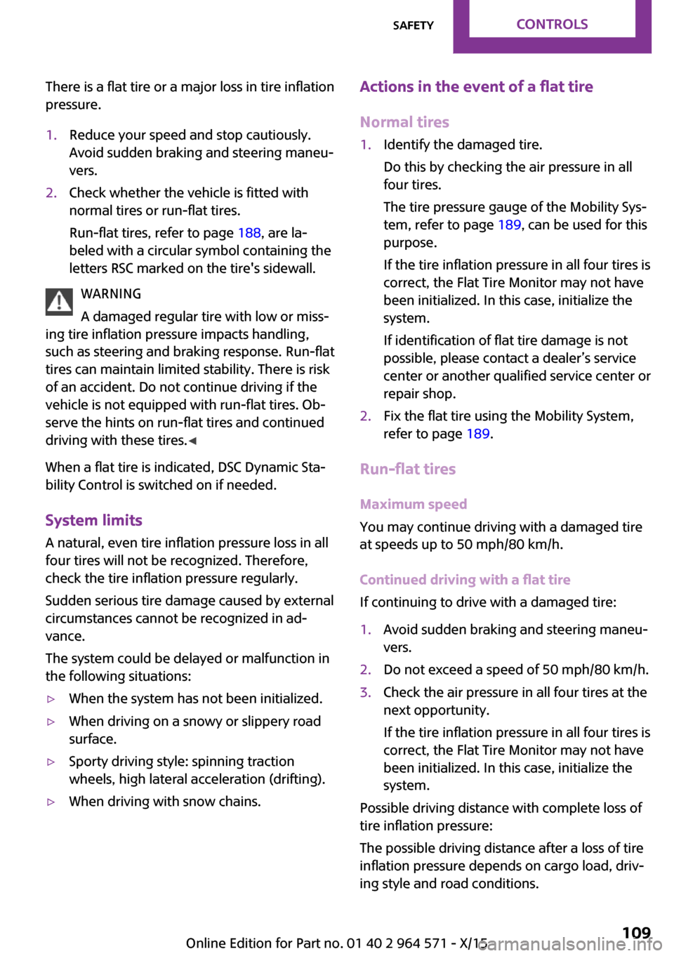
There is a flat tire or a major loss in tire inflation
pressure.
1.Reduce your speed and stop cautiously.
Avoid sudden braking and steering maneu‐
vers.
2.Check whether the vehicle is fitted with
normal tires or run-flat tires.
Run-flat tires, refer to page 188, are la‐
beled with a circular symbol containing the
letters RSC marked on the tire's sidewall.
WARNING
A damaged regular tire with low or miss‐
ing tire inflation pressure impacts handling,
such as steering and braking response. Run-flat
tires can maintain limited stability. There is risk
of an accident. Do not continue driving if the
vehicle is not equipped with run-flat tires. Ob‐
serve the hints on run-flat tires and continued
driving with these tires.◀
When a flat tire is indicated, DSC Dynamic Sta‐
bility Control is switched on if needed.
System limits
A natural, even tire inflation pressure loss in all
four tires will not be recognized. Therefore,
check the tire inflation pressure regularly.
Sudden serious tire damage caused by external
circumstances cannot be recognized in ad‐
vance.
The system could be delayed or malfunction in
the following situations:
▷When the system has not been initialized.▷When driving on a snowy or slippery road
surface.
▷Sporty driving style: spinning traction
wheels, high lateral acceleration (drifting).
▷When driving with snow chains.Actions in the event of a flat tire
Normal tires
1.Identify the damaged tire.
Do this by checking the air pressure in all
four tires.
The tire pressure gauge of the Mobility Sys‐
tem, refer to page 189, can be used for this
purpose.
If the tire inflation pressure in all four tires is
correct, the Flat Tire Monitor may not have
been initialized. In this case, initialize the
system.
If identification of flat tire damage is not
possible, please contact a dealer’s service
center or another qualified service center or
repair shop.
2.Fix the flat tire using the Mobility System,
refer to page 189.
Run-flat tires
Maximum speed
You may continue driving with a damaged tire
at speeds up to 50 mph/80 km/h.
Continued driving with a flat tire
If continuing to drive with a damaged tire:
1.Avoid sudden braking and steering maneu‐
vers.
2.Do not exceed a speed of 50 mph/80 km/h.3.Check the air pressure in all four tires at the
next opportunity.
If the tire inflation pressure in all four tires is
correct, the Flat Tire Monitor may not have
been initialized. In this case, initialize the
system.
Possible driving distance with complete loss of
tire inflation pressure:
The possible driving distance after a loss of tire
inflation pressure depends on cargo load, driv‐
ing style and road conditions.
Seite 109SafetyCONTROLS109
Online Edition for Part no. 01 40 2 964 571 - X/15
Page 110 of 246

A vehicle with an average load has a possible
driving range of approx. 50 miles/80 km.
A vehicle with a damaged tire reacts differently,
e.g., it has reduced lane stability during brak‐
ing, a longer braking distance and different
self-steering properties. Adjust your driving
style accordingly. Avoid abrupt steering ma‐
neuvers or driving over obstacles, e.g., curbs,
potholes, etc.
Because the possible driving distance depends
on how the vehicle is used during the trip, the
actual distance may be shorter or longer de‐
pending on the driving speed, road conditions,
external temperature, cargo load, etc.
WARNING
Your vehicle handles differently when a
run-flat tire is damaged and has low or missing
tire inflation pressure, for example, your lane
stability is reduced when braking, braking dis‐
tances are longer and the self-steering proper‐
ties will change. There is risk of an accident.
Drive moderately and do not exceed a speed of
50 mph/80 km/h.◀
Final tire failure
Vibrations or loud noises while driving can indi‐
cate the final failure of a tire.
Reduce speed and stop; otherwise, pieces of
the tire could come loose and cause an acci‐
dent.
Do not continue driving. Contact a dealer’s
service center or another qualified service cen‐
ter or repair shop.
Intelligent Safety
The concept
Intelligent Safety enables central operation of
the driver assistance system.
The intelligent safety systems can hel prevent
an imminent collision.
▷Front-end collision warning with City Brak‐
ing function, refer to page 111.
▷Person warning with City light braking func‐
tion, refer to page 114.
Information
WARNING
Indicators and warnings do not relieve
from the personal responsibility. Due to system
limits, warnings or reactions of the system may
not be output or they may be output too late or
incorrectly. There is risk of an accident. Adjust
the driving style to the traffic conditions. Watch
traffic closely and actively interfere in the re‐
spective situations.◀
WARNING
Due to system limits, individual functions
can malfunction during tow-starting/towing
with the Intelligent Safety systems activated,
for example approach control warning with
light braking function. There is risk of an acci‐
dent. Switch all Intelligent Safety systems off
prior to tow-starting/towing.◀
Overview
Button in the vehicle
Intelligent Safety button
Switching on/off
Some Intelligent Safety systems are automati‐
cally active after every departure. Some Intelli‐
Seite 110CONTROLSSafety110
Online Edition for Part no. 01 40 2 964 571 - X/15
Page 132 of 246
With front PDC: to reduce false alarms, switch
off automatic PDC activation on obstacle detec‐
tion, for example in car washes, refer to
page 130.
Malfunction
A Check Control message, refer to page 80, is
displayed in the instrument cluster.
Red symbol is displayed, and the range
of the sensors is dimmed on the Control
Display.
PDC has failed. Have the system checked.
Rearview camera
The concept
The rearview camera provides assistance in
parking and maneuvering backwards. The area
behind the vehicle is shown on the Control Dis‐
play.
Information
WARNING
The system does not relieve from the per‐
sonal responsibility to correctly assess the traf‐
fic situation. There is risk of an accident. Adjust
the driving style to the traffic conditions. Watch
traffic and vehicle surroundings closely and ac‐
tively interfere in the respective situations.◀
Overview
Button in the vehicle
Rearview camera
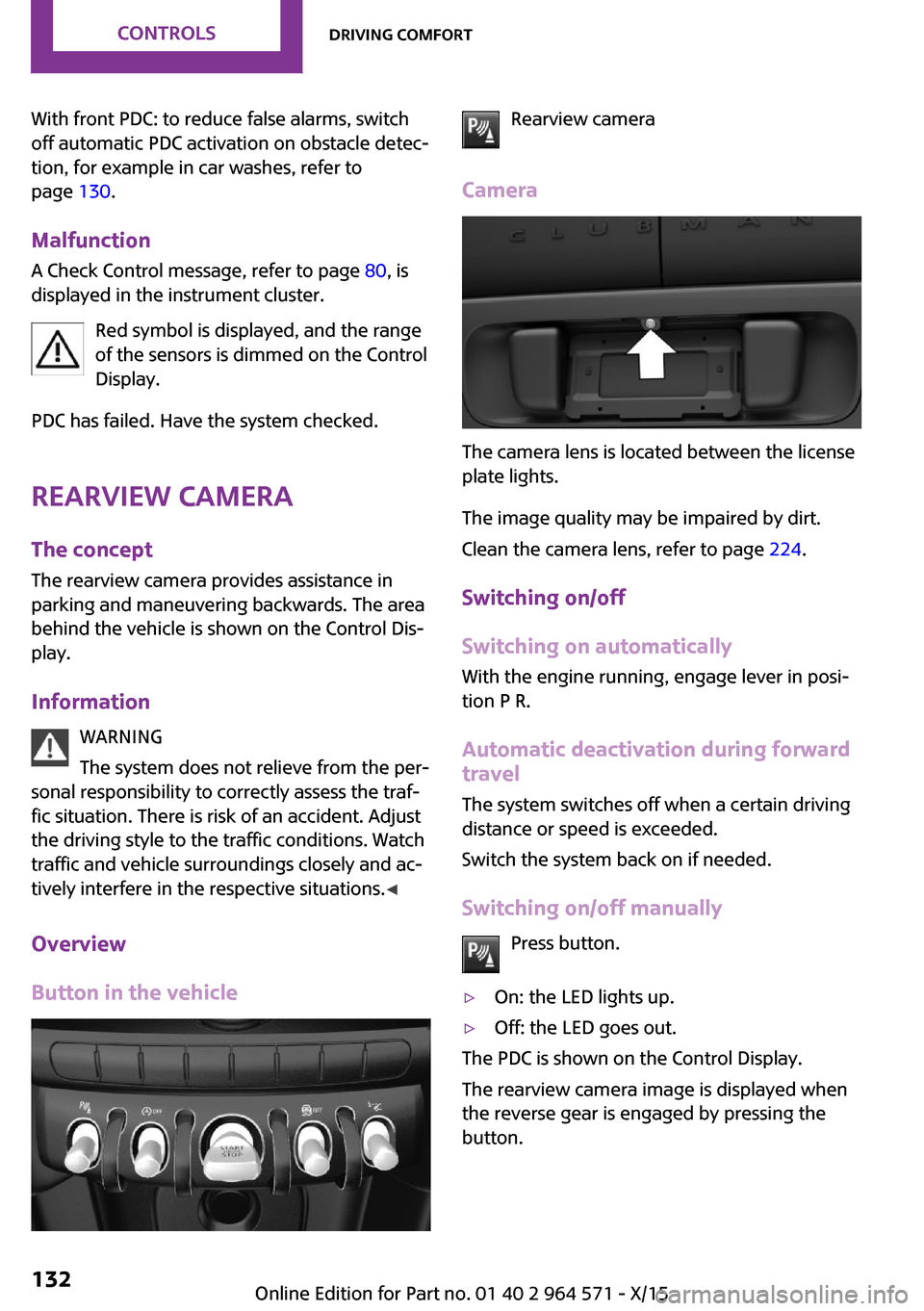
Camera
The camera lens is located between the license
plate lights.
The image quality may be impaired by dirt.
Clean the camera lens, refer to page 224.
Switching on/off
Switching on automatically
With the engine running, engage lever in posi‐
tion P R.
Automatic deactivation during forward
travel
The system switches off when a certain driving
distance or speed is exceeded.
Switch the system back on if needed.
Switching on/off manually
Press button.
▷On: the LED lights up.▷Off: the LED goes out.
The PDC is shown on the Control Display.
The rearview camera image is displayed when
the reverse gear is engaged by pressing the
button.
Seite 132CONTROLSDriving comfort132
Online Edition for Part no. 01 40 2 964 571 - X/15