seat memory MINI Clubman 2016 Owner's Manual (Mini Connected)
[x] Cancel search | Manufacturer: MINI, Model Year: 2016, Model line: Clubman, Model: MINI Clubman 2016Pages: 246, PDF Size: 5.21 MB
Page 51 of 246

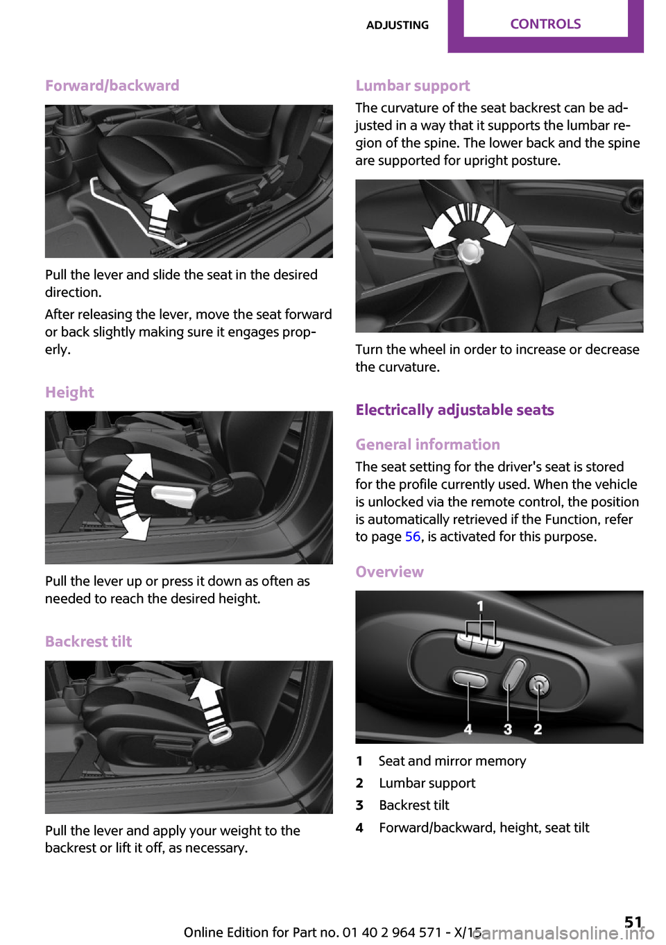
Forward/backward
Pull the lever and slide the seat in the desired
direction.
After releasing the lever, move the seat forward
or back slightly making sure it engages prop‐
erly.
Height
Pull the lever up or press it down as often as
needed to reach the desired height.
Backrest tilt
Pull the lever and apply your weight to the
backrest or lift it off, as necessary.
Lumbar support
The curvature of the seat backrest can be ad‐
justed in a way that it supports the lumbar re‐
gion of the spine. The lower back and the spine
are supported for upright posture.
Turn the wheel in order to increase or decrease
the curvature.
Electrically adjustable seats
General information
The seat setting for the driver's seat is stored
for the profile currently used. When the vehicle
is unlocked via the remote control, the position
is automatically retrieved if the Function, refer
to page 56, is activated for this purpose.
Overview
1Seat and mirror memory2Lumbar support3Backrest tilt4Forward/backward, height, seat tiltSeite 51AdjustingCONTROLS51
Online Edition for Part no. 01 40 2 964 571 - X/15
Page 56 of 246

▷Do not use any accessories, for example pil‐
lows, while driving.◀
Correctly adjusted head restraint
General information
A correctly adjusted head restraint reduces the
risk of injury to cervical vertebrae in the event
of an accident.
Height
Adjust the head restraint so that its center is
approximately at eye level.
Adjusting the height
▷To raise: push.▷To lower: press button, arrow 1, and push
headrest down.
Folding down
▷To lower flaps: press the button, arrow 1,
and press down the head restraint, arrow 2.
▷Fold back up: pull up head restraints.Removing
Fold the seat down, refer to page 153, before
removing the head restraint, otherwise the
head restraint cannot be removed.
1.Pull head restraint up against the resist‐
ance.
2.Press button, arrow 1, and pull the head re‐
straint out completely.
Only remove the head restraint if no one will be
sitting in the seat in question.
Seat and mirror memory
The concept
Two driver's seat and exterior mirror positions
can be stored per profile, refer to page 36, and
called up. Settings for the backrest width and
lumbar support are not stored in memory.
Information
WARNING
There is risk of jamming when moving the
seats. There is risk of injuries or risk of property
damage. Make sure that the area of movement
of the seat is clear prior to any adjustment.◀
WARNING
Using the memory function while driving
can lead to unexpected movements of the seat.
Vehicle control could be lost. There is risk of an
accident. Only retrieve the memory function
when the vehicle is stationary◀
Seite 56CONTROLSAdjusting56
Online Edition for Part no. 01 40 2 964 571 - X/15
Page 58 of 246

Overview1Adjusting 582Left/right, Automatic Curb Monitor3Fold in and out 58
Selecting a mirror
To change over to the other mirror:
Slide the switch.
Adjusting electrically
The setting corresponds to the direction
in which the button is pressed.
Saving positions
Seat and mirror memory, refer to page 56
Adjusting manually
In case of electrical malfunction press edges of
mirror.
Automatic Curb Monitor
The concept
If reverse gear is engaged, the mirror glass on
the front passenger side is tilted downward.
This improves your view of the curb and other
low-lying obstacles when parking, for example.
Activating
1. Slide the switch to the driver's side
mirror position.
2.Engage selector lever position R.
Deactivating
Slide the switch to the passenger side mirror
position.
Fold in and out
CAUTION
Depending on the vehicle width, the ve‐
hicle can be damaged in car washes. There is
risk of property damage. Before washing, fold
in the mirrors by hand or with the button.◀
Press button.
Possible at speeds up to approx.
15 mph/20 km/h.
Folding the mirrors in and out is advantageous
in the following situations:
▷In car washes.▷On narrow roads.▷For folding mirrors back out that were
folded away manually.
Mirrors that were folded in are folded out auto‐
matically at a speed of approx.
25 mph/40 km/h.
Automatic heating
Both exterior mirrors are automatically heated
whenever the engine is running.
Automatic dimming feature
Both exterior mirrors are automatically dim‐
med. Photocells are used to control the Interior
mirror, refer to page 59.
Seite 58CONTROLSAdjusting58
Online Edition for Part no. 01 40 2 964 571 - X/15
Page 214 of 246

Battery replacement
CAUTION
Vehicle batteries that are not compatible
can damage vehicle systems and impair vehicle
functions. There is a risk of personal and prop‐
erty damage. Only vehicle batteries that are
compatible with your vehicle type should be in‐
stalled in your vehicle. Information on compati‐
ble vehicle batteries is available at your dealer’s
service center.◀
After a battery replacement, the manufacturer
of your vehicle recommends that the vehicle
battery be registered on the vehicle by a
dealer’s service center or another qualified
service center or repair shop to ensure that all
comfort features are fully available and that
any Check Control messages of these comfort
features are no longer displayed.
Charging the battery
General information
Make sure that the battery is always sufficiently
charged to guarantee that the battery remains
usable for its full service life.
The battery may need to be charged in the fol‐
lowing cases:
▷When making frequent short-distance
drives.
▷If the vehicle is not used for more than a
month.
▷Steptronic transmission: when parked for
long periods of time in selector lever posi‐
tion D, R or N.
Information
CAUTION
Battery chargers for the vehicle battery
can work with high voltages and currents,
which means that the 12 volt on-board net‐
work can be overloaded or damaged. There is
risk of property damage. Only connect battery
chargers for the vehicle battery to the starting
aid terminals in the engine compartment.◀
Starting aid terminals
In the vehicle, only charge the battery via the
starting aid terminals, refer to page 217, in the
engine compartment with the engine off.
Power failure
After a power loss, some equipment needs to
be newly initialized or individual settings up‐
dated, for example:
▷Time: update.▷Date: update.▷Navigation system: wait for the operability
of the navigation.
▷Seat and mirror memory: store the posi‐
tions again.
▷Glass sunroof: initialize the system, refer to
page 49.
Disposing of old batteries
Have old batteries disposed of by a
dealer’s service center or another quali‐
fied service center or repair shop or
take them to a collection point.
Maintain the battery in an upright position for
transport and storage. Secure the battery so
that it does not tip over during transport.
Fuses
Information
WARNING
Incorrect and repaired fuses can overload
electrical lines and components. There is risk of
fire. Never attempt to repair a blown fuse. Do
not replace a nonworking fuse with a substitute
of another color or amperage rating.◀
Seite 214MOBILITYReplacing components214
Online Edition for Part no. 01 40 2 964 571 - X/15
Page 240 of 246

Interior motion sensor 45
Interior rearview mirror, com‐
pass 148
Internet site 6
Interval display, service re‐
quirements 85
Interval mode 72
J
Jacking points for the vehicle
jack 212
Joystick, Steptronic transmis‐
sion 75
Jump-starting 216
K
Key/remote control 34
Keyless Go, see Comfort Ac‐
cess 41
Key Memory, see Personal
Profile 36
Kickdown, Steptronic trans‐
mission 75
Knee airbag 102
L
Label on recommended
tires 187
Lamp replacement 204
Lamp replacement, front 205
Lamp replacement, rear 207
Lamp replacement, side 211
Language on Control Dis‐
play 92
Lashing eyes, securing
cargo 166
LATCH child restraint sys‐
tem 62
Launch Control 77
Leather, care 222
LED bug light 205
LED headlights 205
LED ring, central instrument
cluster 92
LEDs, light-emitting di‐
odes 204
Letters and numbers, enter‐
ing 25
Light 96
Light-alloy wheels, care 223
Light-emitting diodes,
LEDs 204
Lighter 150
Lighting 96
Lights and bulbs 204
Light switch 96
Load 166
Loading 165
Lock, door 39
Locking/unlocking via door
lock 39
Locking/unlocking with re‐
mote control 37
Locking, automatic 44
Locking, settings 43
Lock, power window 47
Locks, doors, and windows 63
Low beams 96
Low beams, automatic, see
High-beam Assistant 98
Lower back support 52
Lower back support, mechani‐
cal 51
Luggage rack, refer to Roof-
mounted luggage rack 166
Lumbar support 52
Lumbar support, mechani‐
cal 51
M
Maintenance 201
Maintenance require‐
ments 201
Maintenance, service require‐
ments 85
Maintenance system,
MINI 201
Make-up mirror 150
Malfunction displays, see
Check Control 80
Manual air distribu‐
tion 140, 143
Manual air flow 140, 143
Manual brake, see Parking
brake 68
Manual mode, transmis‐
sion 76
Manual operation, door
lock 39
Manual operation, exterior
mirrors 58
Manual operation, fuel filler
flap 178
Manual operation, Park Dis‐
tance Control PDC 130
Manual operation, rearview
camera 132
Manual transmission 74
Manufacturer of the MINI 7
Marking, run-flat tires 188
Master key, see Remote con‐
trol 34
Maximum cooling 142
Maximum speed, display 86
Maximum speed, winter
tires 188
Measurement, units of 92
Medical kit 216
Memory, seat, mirror 56
Menu in instrument cluster 88
Menus, refer to onboard mon‐
itor operating concept 20
Messages, see Check Con‐
trol 80
Microfilter 141, 144
MID - program, driving dy‐
namics 119
MINI Connected, refer to
Integrated Owner's Manual
MINI maintenance sys‐
tem 201
MINIMALISM Analyser 173
MINIMALISM info 172
Seite 240REFERENCEEverything from A to Z240
Online Edition for Part no. 01 40 2 964 571 - X/15
Page 242 of 246

Rear window de‐
froster 141, 144
Recirculated-air filter 144
Recirculated-air
mode 140, 143
Recommended fuel
grade 180
Recommended tire
brands 187
Refueling 178
Remaining range 85
Remote control/key 34
Remote control, blocking 35
Remote control, malfunc‐
tion 39
Remote control, replacing the
battery 34
Remote control, univer‐
sal 146
Replacement fuse 214
Replacing parts 203
Replacing the battery, remote
control 34
Replacing wheels/tires 187
Reporting safety malfunc‐
tions 10
RES CNCL button, see camera-
based cruise control 121
RES CNCL button, see Cruise
control 127
Reserve warning, see
Range 85
Reset, Tire Pressure Monitor
TPM 105
Retaining straps, securing
cargo 166
Retreaded tires 187
Roadside parking lights 97
RON recommended fuel
grade 180
Roofliner 17
Roof load capacity 229
Roof-mounted luggage
rack 166
RSC Run Flat System Compo‐
nent, see Run-flat tires 188
Rubber components,
care 223
Run-flat tires 188
S
Safe braking 163
Safety belt reminder for driv‐
er's seat and front passenger
seat 54
Safety belts 53
Safety belts, care 224
Safety switch, windows 47
Safety systems, airbags 101
Saving fuel 168
Screen, refer to Control Dis‐
play 18
Screwdriver 203
Sealant 189
Seat and mirror memory 56
Seat belts, see Safety belts 53
Seat heating, front 52
Seating position for chil‐
dren 60
Seats 50
Selection list in instrument
cluster 88
Selector lever, Steptronic
transmission 75
Sensors, care 224
Service and warranty 8
Service requirements, Condi‐
tion Based Service CBS 201
Service requirements, dis‐
play 85
SET button, see camera-based
cruise control 121
SET button, see Cruise con‐
trol 127
Settings, locking/unlocking 43
Settings, mirrors 57
Settings on Control Display 91
Settings, storing for seat, mir‐
ror 56
Shift paddles on the steering
wheel 76
Side airbag 101
Signaling, horn 14
Signals when unlocking 44
Sitting safely 50
Size 228
Slide/tilt glass roof 47
Snow chains 192
Socket 150
Socket, OBD Onboard Diag‐
nostics 202
Spare fuse 214
Spare tire, see Emergency
wheel 212
Speed, average 89
Speed limit detection, on‐
board computer 89
Speed limiter, display 86
Speed Limit Information 86
Speed warning 91
Split Doors 40
Split doors via remote con‐
trol 38
Split screen 23
Sport displays 90
SPORT program, Dynamic
Driving Control 119
Sport program, transmis‐
sion 76
Stability control systems 117
Standard view, Head-up Dis‐
play 94
Start/stop, automatic func‐
tion 66
Start/Stop button 64
Start function during malfunc‐
tion 35
Starting the engine 65
Status control display,
tires 105
Status information, onboard
monitor 23
Status of Owner's Manual 7
Steering wheel, adjusting 59
Steptronic Sport transmission,
see Steptronic transmis‐
sion 75
Seite 242REFERENCEEverything from A to Z242
Online Edition for Part no. 01 40 2 964 571 - X/15