service indicator MINI Clubman 2016 Owner's Manual (Mini Connected)
[x] Cancel search | Manufacturer: MINI, Model Year: 2016, Model line: Clubman, Model: MINI Clubman 2016Pages: 246, PDF Size: 5.21 MB
Page 54 of 246

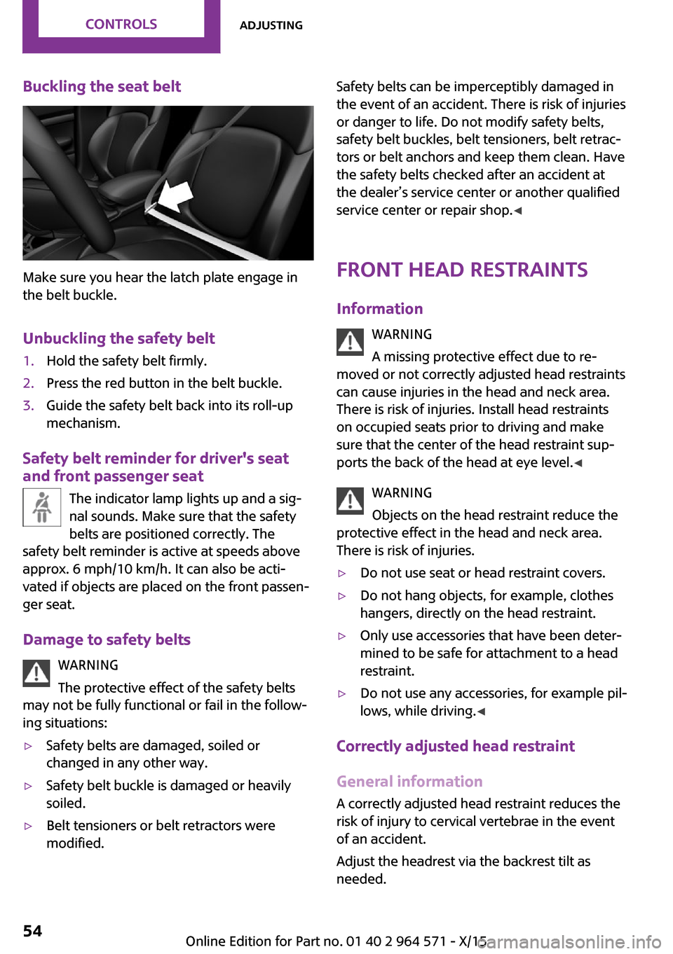
Buckling the seat belt
Make sure you hear the latch plate engage in
the belt buckle.
Unbuckling the safety belt
1.Hold the safety belt firmly.2.Press the red button in the belt buckle.3.Guide the safety belt back into its roll-up
mechanism.
Safety belt reminder for driver's seat
and front passenger seat
The indicator lamp lights up and a sig‐
nal sounds. Make sure that the safety
belts are positioned correctly. The
safety belt reminder is active at speeds above
approx. 6 mph/10 km/h. It can also be acti‐
vated if objects are placed on the front passen‐
ger seat.
Damage to safety belts
WARNING
The protective effect of the safety belts
may not be fully functional or fail in the follow‐
ing situations:
▷Safety belts are damaged, soiled or
changed in any other way.
▷Safety belt buckle is damaged or heavily
soiled.
▷Belt tensioners or belt retractors were
modified.
Safety belts can be imperceptibly damaged in
the event of an accident. There is risk of injuries
or danger to life. Do not modify safety belts,
safety belt buckles, belt tensioners, belt retrac‐
tors or belt anchors and keep them clean. Have
the safety belts checked after an accident at
the dealer’s service center or another qualified
service center or repair shop.◀
Front head restraints
Information
WARNING
A missing protective effect due to re‐
moved or not correctly adjusted head restraints
can cause injuries in the head and neck area.
There is risk of injuries. Install head restraints
on occupied seats prior to driving and make
sure that the center of the head restraint sup‐
ports the back of the head at eye level.◀
WARNING
Objects on the head restraint reduce the
protective effect in the head and neck area.
There is risk of injuries.
▷Do not use seat or head restraint covers.▷Do not hang objects, for example, clothes
hangers, directly on the head restraint.
▷Only use accessories that have been deter‐
mined to be safe for attachment to a head
restraint.
▷Do not use any accessories, for example pil‐
lows, while driving.◀
Correctly adjusted head restraint
General information
A correctly adjusted head restraint reduces the
risk of injury to cervical vertebrae in the event
of an accident.
Adjust the headrest via the backrest tilt as
needed.
Seite 54CONTROLSAdjusting54
Online Edition for Part no. 01 40 2 964 571 - X/15
Page 82 of 246

Illuminated: DSC failed. Have the system
checked by a dealer’s service center or another
qualified service center or repair shop.
For additional information, refer to Dynamic
Stability Control DSC, refer to page 117.
DSC Dynamic Stability Control is deactivated
or DTC Dynamic Traction Control is activated
Dynamic Stability Control DSC is
switched off or Dynamic Traction Con‐
trol DTC is switched on.
For additional information, refer to Dynamic
Stability Control DSC, refer to page 117, and
Dynamic Traction Control DTC, refer to
page 118.
Flat Tire Monitor FTM
The Flat Tire Monitor signals a loss of
tire inflation pressure in a tire.
Reduce your speed and stop cautiously.
Avoid sudden braking and steering maneuvers.
For additional information, refer to Flat Tire
Monitor, refer to page 108.
Tire Pressure Monitor TPM
Illuminated: the Tire Pressure Monitor
signals a loss of tire inflation pressure in
a tire.
Reduce your speed and stop cautiously. Avoid
sudden braking and steering maneuvers.
Flashing and then continuously illuminated: no
flat tire or loss of tire inflation pressure can be
detected.
▷Interference through systems or devices
with the same radio frequency: After leav‐
ing the area of the interference, the system
automatically becomes active again.
▷TPM was unable to complete the reset. Re‐
set the system again.
▷A wheel without TPM electronics is
mounted: Have it checked by a dealer’s
service center or another qualified service
center or repair shop as needed.
▷Malfunction: have the system checked by a
dealer’s service center or another qualified
service center or repair shop.
For additional information, refer to Tire Pres‐
sure Monitor, refer to page 104.
Steering system
Steering system in some cases not
working.
Have the steering system checked by a
dealer’s service center or another qualified
service center or repair shop.
Engine functions
Have the vehicle checked by a dealer’s
service center or another qualified serv‐
ice center or repair shop.
For additional information, refer to On-board
Diagnostics socket, refer to page 202.
Rear fog lamp
Rear fog lights are activated.
For additional information, refer to Rear
fog lights, refer to page 99.
Green lights
Turn signal
Turn signal switched on.
Unusually rapid flashing of the indicator
lamp indicates that a turn signal bulb
has failed.
For additional information, refer to Turn signal,
refer to page 70.
Seite 82CONTROLSDisplays82
Online Edition for Part no. 01 40 2 964 571 - X/15
Page 83 of 246

Parking lights, headlight control
Parking lights or headlights are acti‐
vated.
For additional information, refer to
Parking lights/low beams, headlight control, re‐
fer to page 96.
Front fog lights
Front fog lights are activated.
For additional information, refer to
Front fog lights, refer to page 99.
High-beam Assistant
High-beam Assistant is switched on.
High beams are activated and off auto‐
matically as a function of the traffic sit‐
uation.
For additional information, refer to High-beam
Assistant, refer to page 98.
Cruise control
The system is switched on. It maintains
the speed that was set using the control
elements on the steering wheel.
Blue lights
High beams
High beams are activated.
For additional information, refer to High
beams, refer to page 71.
General lamps
At least one Check Control message is
displayed or is stored.
Text messages
Text messages in combination with a symbol in
the instrument cluster explain a Check Control
message and the meaning of the indicator and
warning lights.
Supplementary text messages
Additional information, such as on the cause of
an error or the required action, can be called up
via Check Control.
With urgent messages the added text will be
automatically displayed on the Control Display.
Symbols
Within the supplementary text, the following
functions can be selected independent of the
check control message.
▷ Display additional information about
the Check Control message in the
Integrated Owner's Manual.
▷ "Service request"
Contact a dealer’s service center or another
qualified service center or repair shop.
▷ "Roadside Assistance"
Contact Roadside Assistance.
Hiding Check Control messages
Press and hold button on turn signal lever.
▷Some Check Control messages are dis‐
played continuously and are not cleared
until the malfunction is eliminated. If sev‐
eral malfunctions occur at once, the mes‐
sages are displayed consecutively.
These messages can be faded for approx.
8 seconds. After this time, they are dis‐
played again automatically.
Seite 83DisplaysCONTROLS83
Online Edition for Part no. 01 40 2 964 571 - X/15
Page 86 of 246

On the Control Display:1. "Vehicle info"2."Vehicle status"3. "Service required"4."§ Vehicle inspection"5."Date:"6.Adjust the settings.7.Confirm.
The entered date is stored.
Gear shift indicator
The concept
The system recommends the most fuel efficient
gear for the current driving situation.
General information
Depending on the vehicle's features and coun‐
try version of the vehicle, the gear shift indica‐
tor is active in the manual mode of the Step‐
tronic transmission and with manual
transmission.
Suggestions to shift gear up or down are dis‐
played in the instrument cluster.
Manual transmission: displaying
ExampleDescriptionFuel efficient gear is set.Shift into fuel efficient gear.Steptronic transmission: displayingExampleDescriptionFuel efficient gear is set.Shift into fuel efficient gear.
Speed limit detection
The concept
Speed limit detection
Speed limit detection shows the current maxi‐
mum permitted speed in the instrument clus‐
ter. The camera at the base of the interior rear‐
view mirror detects traffic signs at the edge of
the road as well as variable overhead sign
posts. Traffic signs with extra symbols for wet
road conditions, etc. are also detected and
compared with the vehicle's onboard data,
such as for the rain sensor, and will be dis‐
played depending on the situation.
With the navigation system, the system takes
into account the information stored in the navi‐
gation data and also displays speed limits
present on routes without signs.
Without a navigation system, the system is sub‐
ject to limitations imposed by technology.
Speed limits with extra text characters are al‐
ways displayed.
Information
Speed limits when towing a trailer are not
shown.
WARNING
The system does not relieve from the per‐
sonal responsibility to correctly assess visibility
and traffic situation. There is risk of an accident.
Adjust the driving style to the traffic conditions.
Seite 86CONTROLSDisplays86
Online Edition for Part no. 01 40 2 964 571 - X/15
Page 98 of 246

System limits
The automatic headlamp control cannot serve
as a substitute for your personal judgment of
lighting conditions.
E. g. the sensors are unable to detect fog or
hazy weather. To avoid safety risks under these
conditions, you should always switch on the
lights manually.
Daytime running lights
General information
Position of switch: , ,
The daytime running lights light up when the
ignition is switched on. After the ignition is
switched off, the parking lights light up in posi‐
tion .
Activating/deactivating
In some countries, daytime running lights are
mandatory, so it may not be possible to deacti‐
vate the daytime running lights.
On the Control Display:
1. "Settings"2."Lighting"3."Daytime running lamps"
Settings are stored for the remote control cur‐
rently used.
Cornering lamp
General information
Position of switch:
When going around corners, the cornering light
also lights the interior area of the curve. Below
a speed of approx. 25 mph/40 km/h when the
turn signal is switched on and the steering an‐
gle is detected, there is automatic activation.
Malfunction
A Check Control message is displayed.
Cornering light is malfunctioning or has failed.
Have the system immediately checked by a
dealer’s service center or another qualified
service center or repair shop.
High-beam Assistant
The concept
The high-beam Assistant detects other traffic
participants early on and automatically
switches the high beams on or off depending
on the traffic situation. The assistant ensures
that the high beams are switched on, whenever
the traffic situation allows. In the low speed
range, the high beams are not switched on by
the system.
General information
The system responds to light from oncoming
traffic and traffic driving ahead of you, and to
adequate illumination, e.g., in towns and cities.
The driver can intervene at any time and switch
the high beams on and off as usual.
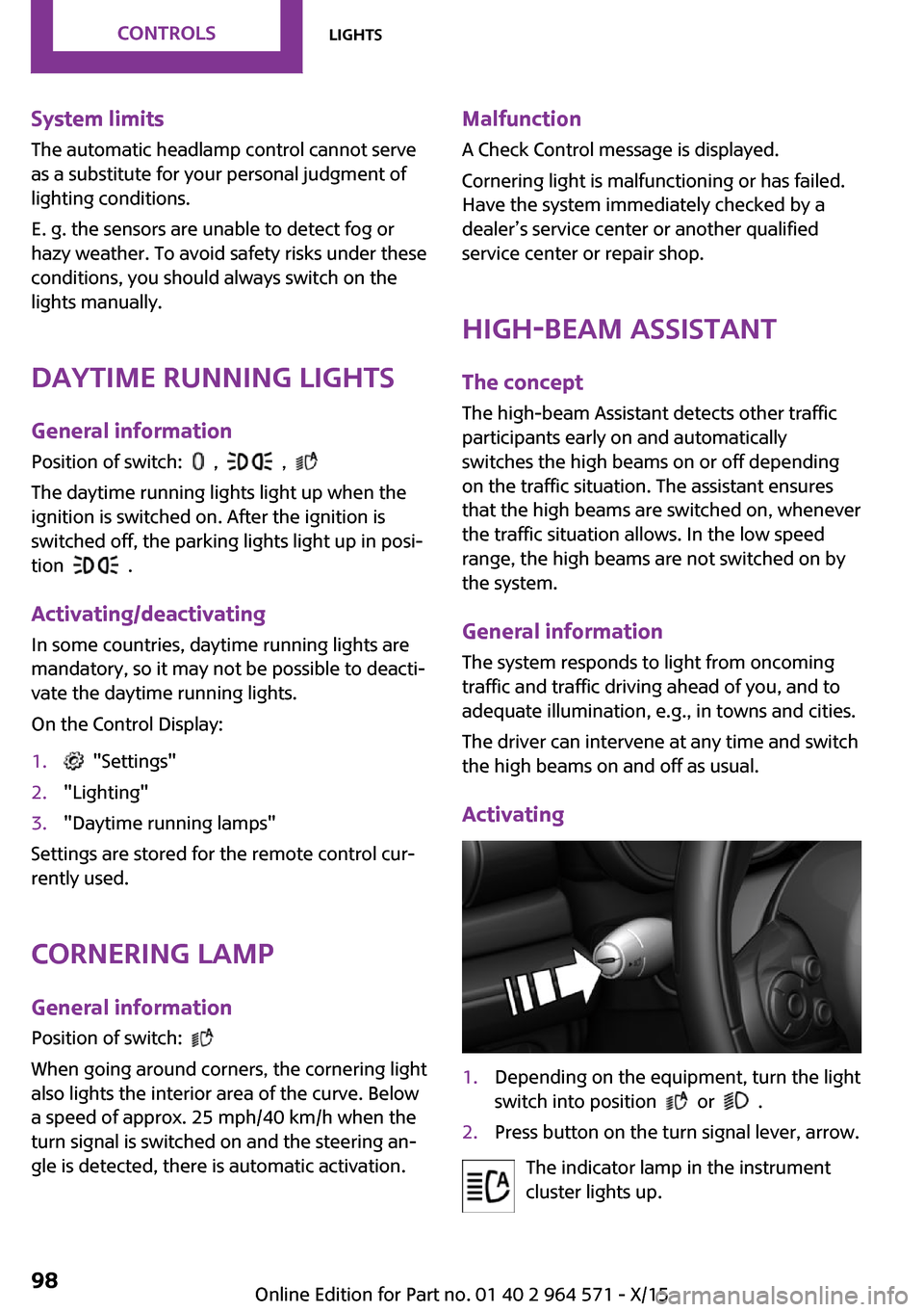
Activating
1.Depending on the equipment, turn the light
switch into position or .
2.Press button on the turn signal lever, arrow.
The indicator lamp in the instrument
cluster lights up.
Seite 98CONTROLSLights98
Online Edition for Part no. 01 40 2 964 571 - X/15
Page 103 of 246

tion, the airbag system could not trigger as in‐
tended in the event of an accident despite re‐
spective accident severity. There is risk of
injuries or danger to life. Have the airbag sys‐
tem checked, repaired, dismantled and scrap‐
ped by a dealer’s service center or another
qualified service center or repair shop.◀
Correct function
When the ignition is switched on, the
warning lamp in the instrument cluster
lights up briefly and thereby indicates
the operational readiness of the entire airbag
system and the belt tensioner.
Airbag system malfunctioning
▷Warning lamp does not come on when the
ignition is turned on.
▷The warning lamp lights up continuously.
Automatic deactivation of the front-
seat passenger airbags
The concept
The system reads if the front passenger seat is
occupied by measuring the human body's re‐
sistance.
Front, knee and side airbag on the front pas‐
senger's side are either activated or deacti‐
vated.
Information
Before transporting a child on the front passen‐
ger seat, refer to the safety notes and instruc‐
tions for children on the front passenger seat,
see Children.
WARNING
The ensure the front-seat passenger air‐
bag function, it must be detected, whether a
person occupies the front passenger seat. The
entire seat cushion area must be used for this
purpose. There is risk of injuries or danger to
life. Make sure that the front passenger keeps
his or her feet in the floor area.◀
Malfunction of the automatic
deactivation system
When transporting older children and adults,
the front-seat passenger airbags may be deac‐
tivated in certain sitting positions. In this case,
the indicator lamp for the front-seat passenger
airbags lights up.
In this case, change the sitting position so that
the front-seat passenger airbags are activated
and the indicator lamp goes out.
If it is not possible to activate the airbags, have
the person sit in the rear.
To enable correct recognition of the occupied
seat cushion.
▷Do not attach covers, cushions, ball mats or
other items to the front passenger seat un‐
less they are specifically determined to be
safe for use on the front passenger seat.
▷Do not place any electronic devices on the
passenger seat if a child restraint system is
to be installed on it.
▷Do not place objects under the seat that
could press against the seat from below.
▷No moisture in or on the seat.
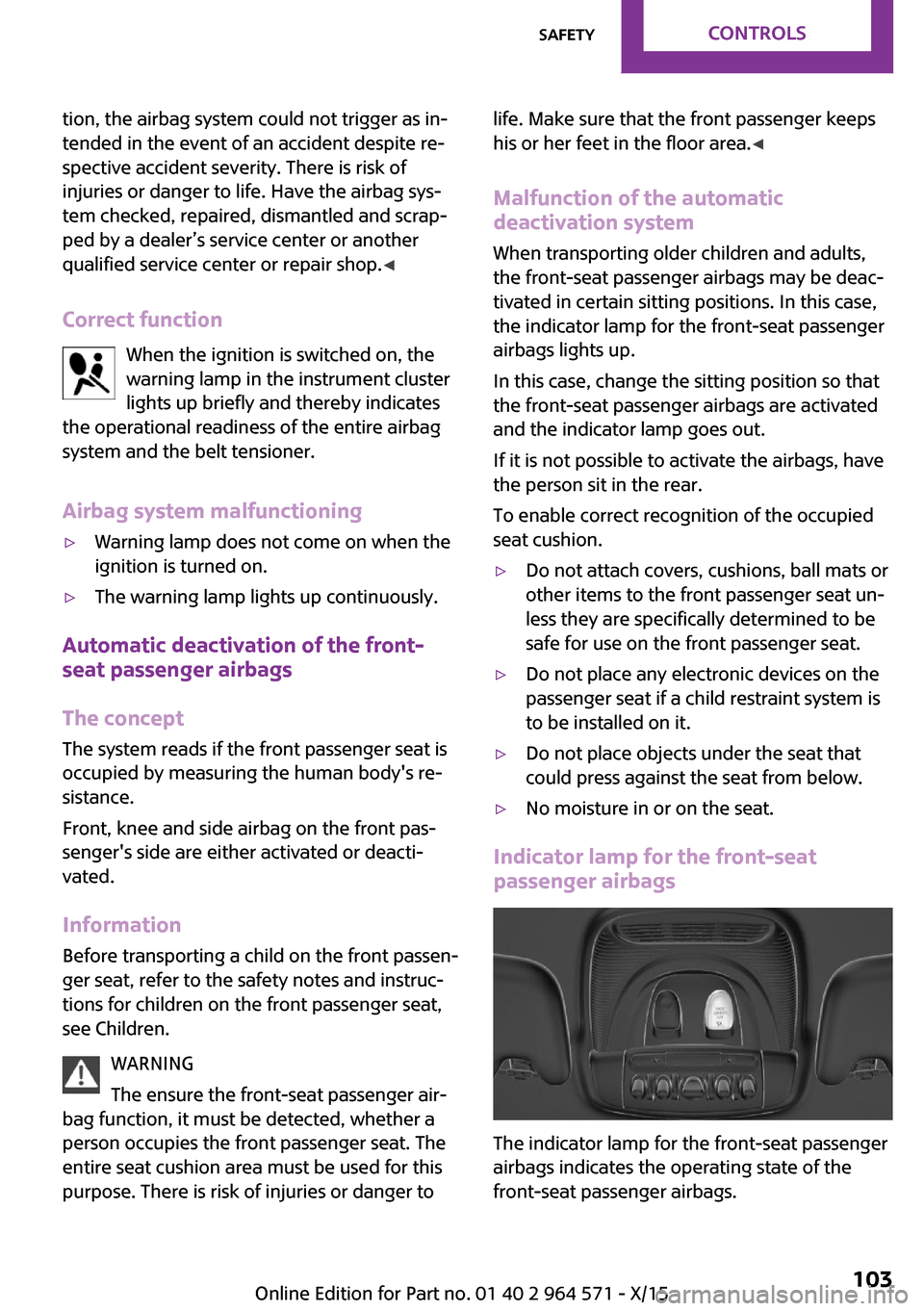
Indicator lamp for the front-seat
passenger airbags
The indicator lamp for the front-seat passenger
airbags indicates the operating state of the
front-seat passenger airbags.
Seite 103SafetyCONTROLS103
Online Edition for Part no. 01 40 2 964 571 - X/15
Page 110 of 246

A vehicle with an average load has a possible
driving range of approx. 50 miles/80 km.
A vehicle with a damaged tire reacts differently,
e.g., it has reduced lane stability during brak‐
ing, a longer braking distance and different
self-steering properties. Adjust your driving
style accordingly. Avoid abrupt steering ma‐
neuvers or driving over obstacles, e.g., curbs,
potholes, etc.
Because the possible driving distance depends
on how the vehicle is used during the trip, the
actual distance may be shorter or longer de‐
pending on the driving speed, road conditions,
external temperature, cargo load, etc.
WARNING
Your vehicle handles differently when a
run-flat tire is damaged and has low or missing
tire inflation pressure, for example, your lane
stability is reduced when braking, braking dis‐
tances are longer and the self-steering proper‐
ties will change. There is risk of an accident.
Drive moderately and do not exceed a speed of
50 mph/80 km/h.◀
Final tire failure
Vibrations or loud noises while driving can indi‐
cate the final failure of a tire.
Reduce speed and stop; otherwise, pieces of
the tire could come loose and cause an acci‐
dent.
Do not continue driving. Contact a dealer’s
service center or another qualified service cen‐
ter or repair shop.
Intelligent Safety
The concept
Intelligent Safety enables central operation of
the driver assistance system.
The intelligent safety systems can hel prevent
an imminent collision.
▷Front-end collision warning with City Brak‐
ing function, refer to page 111.
▷Person warning with City light braking func‐
tion, refer to page 114.
Information
WARNING
Indicators and warnings do not relieve
from the personal responsibility. Due to system
limits, warnings or reactions of the system may
not be output or they may be output too late or
incorrectly. There is risk of an accident. Adjust
the driving style to the traffic conditions. Watch
traffic closely and actively interfere in the re‐
spective situations.◀
WARNING
Due to system limits, individual functions
can malfunction during tow-starting/towing
with the Intelligent Safety systems activated,
for example approach control warning with
light braking function. There is risk of an acci‐
dent. Switch all Intelligent Safety systems off
prior to tow-starting/towing.◀
Overview
Button in the vehicle
Intelligent Safety button
Switching on/off
Some Intelligent Safety systems are automati‐
cally active after every departure. Some Intelli‐
Seite 110CONTROLSSafety110
Online Edition for Part no. 01 40 2 964 571 - X/15
Page 169 of 246

By maintaining a suitable distance to the vehi‐
cle driving ahead of you.
Driving smoothly and proactively reduces fuel
consumption.
Avoid high engine speeds
As a rule: driving at low engine speeds lowers
fuel consumption and reduces wear.
Use 1st gear to get the vehicle moving. Starting
with the 2nd gear, accelerate rapidly. When ac‐
celerating, shift up before reaching high engine
speeds.
When you reach the desired speed, shift into
the highest applicable gear and drive with the
engine speed as low as possible and at a con‐
stant speed.
The gear shift indicator, refer to page 86, of
your vehicle indicates the most fuel efficient
gear.
Use coasting conditions
When approaching a red light, take your foot
off the accelerator and let the vehicle coast to a
halt.
For going downhill take your foot off the accel‐
erator and let the vehicle roll.
The flow of fuel is interrupted while coasting.
Switch off the engine
during longer stops
Switch off the engine during longer stops, for
example, at traffic lights, railroad crossings or in
traffic congestion.
Auto Start/Stop function
The Auto Start/Stop function of your vehicle au‐
tomatically switches off the engine during a
stop.
If the engine is switched off and then restarted
rather than leaving the engine running con‐
stantly, fuel consumption and emissions are re‐
duced. Savings can begin within a few seconds
of switching off the engine.
In addition, fuel consumption is also deter‐
mined by other factors, such as driving style,
road conditions, maintenance or environmental
factors.
Switch off any functions
that are not currently
needed
Functions such as seat heating and the rear
window defroster require a lot of energy and
consume additional fuel, especially in city and
stop-and-go traffic.
Therefore, switch off these functions if they are
not actually needed.
Have maintenance car‐
ried out
Have vehicles maintained regularly to achieve
optimal vehicle efficiency and service life. MINI
recommends that maintenance work be per‐
formed by a MINI service center.
Also note the MINI maintenance systems, refer
to page 201.
GREEN Mode
The concept
The GREEN Mode supports a driving style that
saves on fuel consumption. For this purpose,
the engine control and comfort features, e. g.
the climate control output, are adjusted.
For Steptronic transmission:
Seite 169Saving fuelDRIVING TIPS169
Online Edition for Part no. 01 40 2 964 571 - X/15